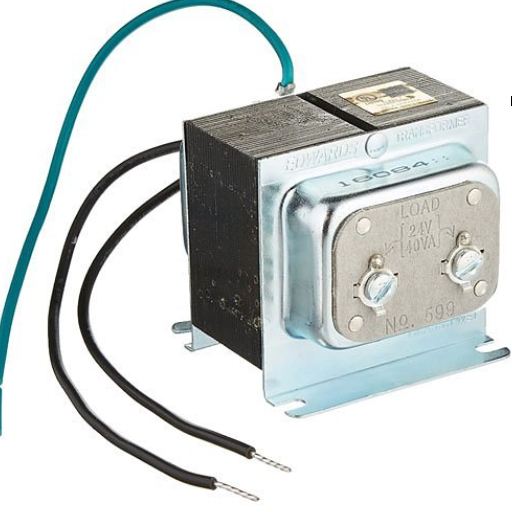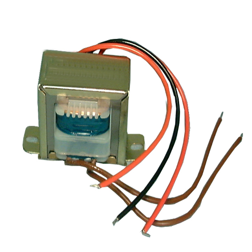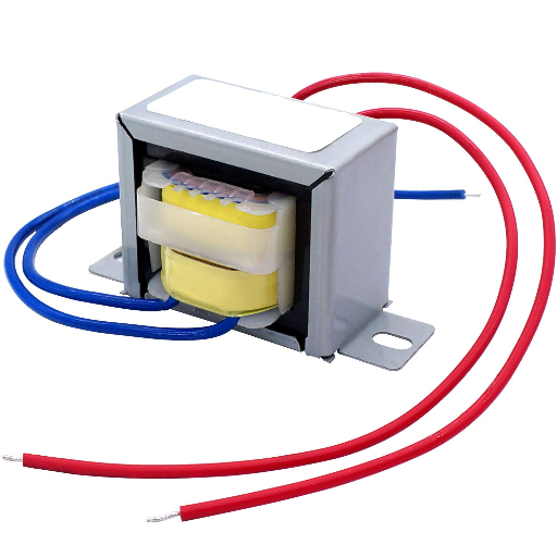

Electrical transformers have been instrumental in supplying power to human settlements running businesses, and industries, being a medium for energy transfer with varying voltage levels. When considering installing or servicing the equipment, one must know the transformer wire color code for safety, accuracy, and good performance. Some incorrect wiring can lead to an immediate fault in the equipment, and there may be a threat of electrical hazard, while at times, worse, it can bring about complete system failure. This write-up outlines the major primary and secondary wire color codes for transformers, explaining their meaning for the benefit of electricians, engineers, and home hobbyists alike. This guide should therefore arm you with sufficient knowledge for confidently and effectively working on transformer wiring procedures, whether you are experienced or just beginning.
Introduction to Transformer Wiring Color Codes

Transformer wiring color codes play a fundamental role in alerting the danger, or contribution to the hazard, that particular wiring may have if mishandled. The standardization forms a method of identifying the various functions of the wires—for example, live, neutral, or ground—so that inappropriate connections may be prevented while working on the installation or during maintenance. Usually, the colors applicable to primary wires indicate high-voltage inputs, whereas those provided for secondary side wires correspond to a lower output voltage. By systems, black and red on the primary side indicate different phases, whilst white indicates neutral. Colors on the secondary have to be different: green normally stands for ground. Always refer to the transformer manufacturer’s documentation and local electrical codes for accurate guidelines.
Importance of Wire Color in Electrical Systems
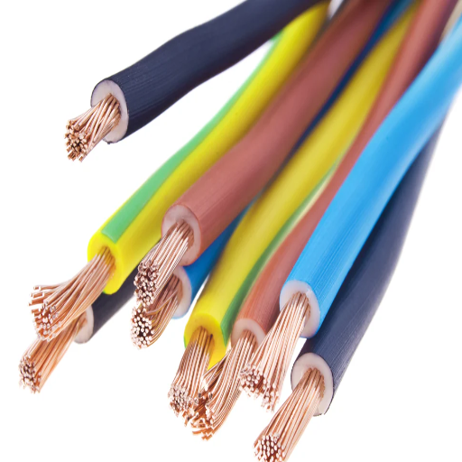
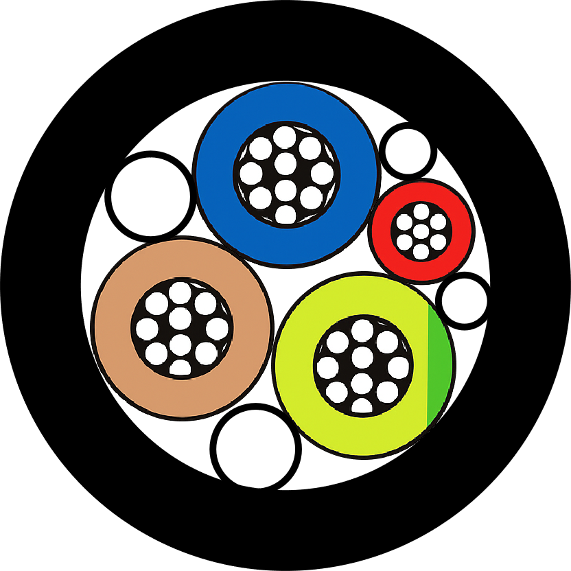
Wire colors, being one of those things, ensure the safety, arrangement, and efficiency of electrical systems. Around the world, differing regions use their own specific standards for the color coding of wires, such as the National Electrical Code (NEC) in the U. S. or IEC standards in most countries. For example, in the United States, black wires normally carry phase or live connections, white wires mean neutral, and green or green with yellow stripe is for grounding. However, the Europeans have their own convention with brown used for live, blue for neutral, and green/yellow for ground.
Sticking to these codes is a service to prevent electrical misadventures such as short circuits or electrocutions caused by miswiring. According to ESFI, improper wiring causes more than 50,000 electrical fires every year in the U. S. Knowing proper wire color code helps to keep electricians and engineers from such dangerous situations.
While at it, wire color coding makes it easier to troubleshoot and maintain: Technicians can tell the purpose of each wire without conducting elaborate tests-and they probably already know. It is, thus, rather significant for complex installations like industrial machines or some multi-phase power systems, where misidentification may incur heavy downtime and repair costs.
Overview of Transformer Types and Their Applications
Transformers play a major role in electrical systems, transferring electrical energy from one circuit to another while modifying voltage and current levels suitable for a particular application. Here is a brief overview of common transformer types and their applications:
Step-Up and Step-Down Transformers
Essentially, step-up transformers increase voltage levels for efficient long-distance transmission of power, whereas step-down transformers decrease voltage for local distribution, rendering it safe in a residential or commercial setup.
Power Transformers
Power transformers are larger, high-voltage devices that allow for efficient management, transmission, and distribution of power. Their peak performance occurs during full load.
Distribution Transformers
Seen on the supply end of the power networks, these transformers reduce high voltage levels to usable voltage limits that can be applied in homes and industries. These transformers operate with high efficiency under low loads. With their majority being raised on utility poles or being underground, these serve an important role in distribution.
Isolation Transformers
Used to electrically isolate the circuits for safety to prevent shocks or interference, they are used in sensitive equipment or industrial control systems.
Autotransformers
An autotransformer is more compact, lighter, and efficient than ordinary transformers because a single winding is used as a primary as well as secondary winding. They are, in general, used in voltage regulation of equipment such as generators or motors.
Instrument Transformers (Current and Potential Transformers)
Thus, instrument transformers are specialized for measuring and monitoring purposes. Current transformers (CT) and potential transformers (PT) provide accurate readings at high voltages while ensuring safety and protection to electrical systems.
Each transformer has been designed for specific voltage, current, and environmental parameters to fit into all kinds of industrial, commercial, or residential applications. Their range of applications and reliability make them an absolute necessity in present-day electrical networks.
Understanding Primary and Secondary Wiring
Primary and secondary wiring refer to the two major circuits within a transformer. The primary winding is connected to the power source as input and takes electrical energy in at high voltage. This energy is imparted via electromagnetic induction to the secondary winding that provides output at either lower voltage or at a voltage different from that of the primary winding depending upon the type of the transformer.
There are several aspects to keep in mind during the proper installation of primary and secondary wiring to ensure safety and efficiency of an electrical system. The primary winding of a transformer usually has a larger number of wire turns for operation at high voltage, whereas the secondary winding has fewer turns for low-voltage output. Insulation and grounding must be incorporated into the design of both primary and secondary windings to guard against any electrical hazards, whereas the load requirements will ascertain the final functioning of the transformer.
Standard Color Codes for Transformer Wires

Transformer wire colors can change from region to region, with a few other standards commonly used:
North American (ANSI/NEC):
- Primary wiring of high voltage (H1, H2): Usually used black, red, or orange color.
- Secondary wiring of low voltage (X1, X2, X3): Usually white, black, and red.
International (IEC):
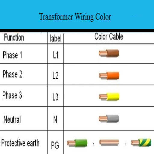
- Primary wiring: Brown (L1), Black (L2), and Gray (L3).
- Secondary wiring (neutral or ground): Blue in Neutral, and Green/Yellow in Ground.
重要: Please always consult regional electrical standards and regulations to remain compliant and safe.
Common Color Codes Used in Electrical Transformers
Electrical transformer wiring color codes are essential to ensure safety, correct installation, and indeed maintenance. Here is a consolidated table produced from major reference standards and the most widely adopted practices worldwide:
| Region/Standard | 線材類型 | 顏色代碼 | 目的 |
|---|---|---|---|
| America (ANSI/NEC) | Primary Voltage (High Voltage) | Black, Red, or Orange | Phase identification |
| America (ANSI/NEC) | Secondary Voltage (Low Voltage) | White (Neutral), Black or Red (Hot) | 120/240V residential systems |
| America (ANSI/NEC) | Grounding Wires | Green or Bare Copper | Safety grounding |
| International (IEC) | Primary (Three-phase) | Brown (L1), Black (L2), Gray (L3) | Three-phase high voltage identification |
| International (IEC) | Secondary (Neutral) | 藍色 | Neutral wire |
| International (IEC) | Secondary (Ground) | 綠色/黃色 | Grounding wire |
Key Applications From Voltage Systems:
- Single-Phase Transformers: Colors distinguish line (live), neutral, and earth for smaller systems generally for residential or light commercial purposes.
- Three-Phase Transformers: Phases must be clearly identified as L1, L2, and L3 to ensure that loads are balanced and that correct rotation is used. Not using the local color codes will give rise to operational errors.
安全警告: In all installations and maintenance work always verify with the local electrical codes and consult certified professional to avoid risks. Proper labeling and adherence to standards are the bare minimum that should be met while dealing with electrical transformer wiring.
Wire Color Identification for Primary and Secondary Circuits
Proper wire color identification for primary and secondary circuits is important in ensuring safety, standards, compliance, and easy troubleshooting. Black, red, or blue wires are usually used for the primary circuit in the United States in three phases. The black one usually represents phase A, red for phase B, and blue for phase C. For the neutral line, the color is either white or gray, and the earth line must be green or green with a yellow stripe.
For secondary circuits, the color standards may vary depending on the configurations of the transformers. Most generally in the low-voltage system, black will be for phase A, red for phase B, blue for phase C, and white or gray for neutral. Green or green with a yellow stripe will be for the earth wire in all secondary circuit installations.
Always refer to the National Electrical Code (NEC) or regional regulations to confirm color-coding requirements since these might vary with the region or actual application. Double-checking and proper labeling avoids confusion, particularly during maintenance.
Neutral and Earth Wire Color Codes
Neutral and earth wires serve essential roles in safety and proper functioning of the circuits. The generally assigned color to the neutral wire is white or gray in the United States setting, as stated by the NEC. As for the earth wires, green or green with a yellow strip is the accepted standard. These colors ensure the clear identification of wires and help avoid wiring errors.
Color codes can also vary worldwide. For instance, Europe labels a neutral wire as blue and an earth wire as green with a yellow strip. In fact, this coding remains the same for most installations in the United Kingdom. Australia seems to be following a similar pattern with blue for neutral and green with a yellow strip for earth. Always check the applicable local regulations and standards, such as IEC or NEC, before proceeding with any electrical work. Downside risks are minimized, and the short term safety and reliability of the operation of the electrical systems are ensured by keeping to proper codes.
Electrical Safety and Wiring Color Codes

Some important points should be considered concerning electrical safety questions and wiring color codes:
Why are wiring color codes considered important?
Wiring color codes are important to signify functioning of a wire and thereby preventing electrical hazards as well as for ensuring adherence to local regulations.
What do the standard colors of a wire represent?
Normally, brown is for live or active wire (red in old wiring systems), blue is for neutral (black in old wiring systems), and green with yellow strips is for earth or ground. But these colors can vary by country; always check local codes.
How do I work safely?
Ensure that power is switched off while doing any electrical work. Always follow the latest standards in your area, for example IEC or NEC: consider working with a licensed electrician when the task is complicated.
This is how your safety and reliability of the electrical system will be ensured.
Safety Precautions When Working with Transformer Wires
When working on transformer wiring, safety must be paramount as this is an electrical hazard. Best practice-based concise answers and tips are below:
Why is wire color coding important?
Wire color coding makes for proper identification of live, neutral, and ground wires and minimizes chances of wrong connections. Always check the color codes with respect to the local standards because these may vary from place to place.
How do transformer wires differ from normal wires?
Transformer wires are invariably insulated for high voltages, including primary and secondary windings. It is therefore crucial that these wires be properly identified for their correct installation and operation.
How can one safely perform electrical work?
- Turn off the power supply before starting any work.
- Go on and use insulated tools; gloves and safety goggles would also prove effective.
- Keep in mind any local regulation, maybe IEC or NEC standards.
- For a complex installation, always seek the opinion of a qualified electrician.
Critical Safety Note: Remember: transformers go for high voltage, and any mishandling will cause very serious injuries or damages. Check everything twice while installing or maintaining, and always be aware of the positions of the live wires.
Identifying Wiring Issues Through Color Codes
Wiring color codes are an essential guide for correcting probable electrical problems, assuring safety, and maintaining system integrity. Different nations will apply specific color standards, like the NEC (National Electrical Code) in the US or the IEC standards in Europe. Following are some commonly accepted wiring color codes and their corresponding significances:
- Black and Red: Live or hot wiring. If an opening black/red wire strikes a break in the power flow, causing a hazard, always look for wear or improper connection on the black/red wire.
- White Wires (in the US) or Blue Wires (Europe): Neutral. Damage or lack of proper connection on these wires fail to complete the proper circuitry, creating malfunctions within the system.
- Green and Yellow/Green Wires: Grounding. Broken or disconnected ground wires will remove any chance at fault protection, resulting in electric shock risk.
For wiring problems, first inspect the wires for fraying, discoloration, and incorrect connections; alternatively, one may use a multimeter to test functions like voltage and continuity to ascertain that the wire does perform correctly. In any case, one should keep in mind the colors of wires based on respective standards for their region and replace damaged wires, or repair before creating dangerous hazards. Should the person consider themselves unsure, it would be of utmost importance to consult with an electrician for true compliance and safety.
Best Practices for Wiring Maintenance
Whatever the electrical system, proper wiring maintenance is a must for safety and efficiency. Some key practices are:
Regular Inspections
These are visual inspections of all wiring every couple of months to spot signs of wear-and-tear-like fraying, discoloration, or exposed wires. Give any unusual odors your attention, as they can be signs of overheating.
Keep Wires Organized
The wires, once bundled neatly, are secured with cable ties or conduits to prevent tangling and possible damage from a human source. Never do so by overloading the circuits; properly distribute the electrical loads.
Check for Loose Connections
Loose connections should be tightened as they may pose safety hazards and interrupt power supply. Tighten firmly with a screwdriver or an appropriate tool.
Test Systems Frequently
Check the voltage, continuity, and amperage in circuits with a multimeter. Testing can confirm whether the wires function correctly and help prevent potential electrical failures.
Update Wiring When Necessary
When wiring is considered outdated or damaged, replace it with materials of the most current electrical code. For instance, aluminum wiring may have to be replaced for copper wiring to improve safety.
Protect Wiring from Hazards
Keep wires away from heat, carpets, or heavy-traffic areas. Proper insulation must be provided to lessen the possibility of short censorship or damage caused by moisture.
Hire Professionals When Needed
For complex or large-scale projects, one should always consult a licensed electrician to meet local regulations and assure proper safety and long life.
Following these will lessen the likelihood of electrical issues and keep the wiring systems from deteriorating over time.
Application of Transformer Wire Color Codes

Wire color codes for transformers assist in the identification of the wire functions during installation or servicing. In general, codes applied to primary side wires are different from those applied to secondary side wires for the sake of clarity. Typically:
- Primary Side Wires (incoming power): Usually black and white.
- Secondary Side Wires (output connections): Red and yellow are common colors for step-down transformers.
These codes help to avoid mistakes in connections, promote safety, and aid in troubleshooting. Always follow the instructions in the specific transformer manual or local standards for proper guidance.
How to Apply Color Codes in Different Electrical Systems
Color-coding in electrical installations is made purposeful for safety, operation, and conformity to local regulations. One should always identify the voltage level and purpose of the system first since this will be paramount to choosing the applicable color code. For example, the color code for an industrial high-voltage system might be entirely different from that of a residential wiring system.
Common practices are:
- Ground Wires: Normally green or green with yellow stripes.
- Neutral Wires: Usually white or gray.
- Live/Hot Wires: The colors vary-black, red, or blue, and so forth-to indicate the phases and types of systems.
Depending on other particulars, such as a three-phase system, individual colors are used for each phase (e.g., black, red, and blue per US code for 120/240 volt systems). Similarly, in international systems, such as IEC standards, brown, black, and gray are colors used for line wires.
First, before any electrical work begins, consult the NEC, IEC guidelines, local standards, etc., to verify the exact color codes to be known and used. Always use a licensed tradesman for systems that are complicated and/or risky to install. A proper application of such code along with proper labeling will limit errors and promote reliability.
Real-World Examples of Wiring Applications
住宅佈線
Residential Wiring is primarily concerned with making safe and efficient electrical installations within homes. These installations may include lighting, sockets, and such appliances as refrigerators and washing machines. Most of the time, these wires are color-coded to denote live, neutral, or ground wires. As an example, in the U. S., black and sometimes red are used for live wires, white is used for neutral wires, while green or bare copper is always used for ground connections.
Industrial Wiring
Industrial Wiring generally deals with high-voltage wiring for the power supply to heavy machinery and equipment. These wiring applications require heavy insulation and promulgation of proper safety standards as laid down by the NEC or IEC. Among others, this includes wiring a motor control center for large production lines where the wiring has to be done accurately to ensure efficiency and safety for the employees working there.
Data and IT Wiring
Today, Ethernet cabling for the internet is typical data wiring employed by companies for communications. These systems incorporate structured wiring solutions for smooth connectivity, with minimum interference and maximum speeds. Color-coding is utilized for this purpose, wherein different colors are assigned for transmit, receive, or ground connections.
Automotive-Wiring System
These systems connect different electrical components in a vehicle-wiring and control systems-for example, headlights, batteries, and onboard computers. Standard color codes vary depending upon the manufacturer, but the circuits must remain functional and reliable while enduring vibration, heat, and moisture.
再生能源系統
Renewable energy wiring involves the interfacing of panels, inverters, and batteries. Due to the varied levels of voltage, safety codes have to be observed by all the installations and usually involve the use of materials that are sturdy and weather-resistant, especially for outdoor applications.
Future Trends in Wiring Color Standards
One key aspect of the evolution in electrical systems is hence the trend toward global harmonization of wiring color standards to eradicate confusion in international projects. Many organizations promote use of the IEC 60446 standard, which makes identification easier by designating particular colors according to the function of the cable. Neutral wires will hence be assigned blue; green-yellow would be for earth. On the other hand, smart technologies and renewable energy systems are creating needs for more complex wiring designs, mixing marked cables for data and power. The future is thus shaped by innovations such as biodegradable insulation and color-coded conductors for high-end applications, aiming for sustainability and safety.
變壓器接線的維護和故障排除

Transformer wiring maintenance is critical in ensuring optimum performance and the prevention of system failures. Maintenance activities must commonly include the inspection of wiring for any wear, heating, or corrosion. Furthermore, connections must be checked and tightened to avoid loose contacts, which may otherwise cause arcing or voltage drops. An insulation resistance testing procedure is carried out to discover potential deterioration within cable insulation. Likewise, thermal imaging may be used to track heat spots that could signify an overloading or bad connection.
When dealing with transformer wiring problems, immediately verify all connections against the placed wiring diagram to ascertain its being correctly assembled. Use multimeter operations continuity, voltage, and resistance to detect any aberrations. Check for visible damage to wires and insulation that might be melting. For other compound problems, one would have to look into an advanced level of testing equipment such as a megohmmeter or a TTR tester. These will help to ascertain the integrity of wiring and performance of the transformers, respectively. Thus, by considering routine maintenance and troubleshooting, one can quickly come to grips with the more common problems.
Identifying Common Wiring Issues
Wiring may raise numerous problems, ranging from trivial inconveniences to grave dangers. Some of the usual issues may include:
Loose Connections
Loose wiring may cause slight flickering of lights, sometimes power failure, or heating. Make sure all connections are tight, especially in junction boxes and outlets.
Overloaded Circuits
With an overloaded circuit, breakers trip almost immediately or fuses blow. Electrical loads should be redistributed or big enough to accommodate the loads.
Faulty Outlets or Switches
An outlet or switch may come to be defective due to damage or wear. Prompt replacement of damaged outlets or switches reduces the risk of being shocked.
Damaged Insulation
Wires with frayed or melted insulation are vulnerable to short circuits and electrical fires. Replace the affected wires, and inspect for any heat sources contributing to the damage.
Incorrect Wiring or Poor Installation
If miswiring occurs, the systems may not function correctly or become hazardous. Check once again its installations against the diagrams and the standards to be followed and fix the errors at once.
To fix such problems, one must search carefully, use the right tools, and give priority to safety. If the problem stands unresolved or if you find it beyond your capability, go ahead and ask a professional for help-the services of a licensed electrician are advised.
Regular Maintenance Checks for Safety
A must-have for me is safety and potential issues prevention through checkups. I check wiring, connections, and equipment for any observable wear and tear, loose connections, or signs of overheating. These checks are scheduled regularly so that I can prevent issues by patching minor problems before turning into major malfunctions. If I spot anything questionable, or anything outside my scope, I don’t hesitate; I call a licensed electrician to get the ball rolling safely and effectively.
Guidelines for Rewiring and Upgrading Transformers
Transformers require rewiring and upgrading with meticulous planning and safety standards for their best performance and longer lifespan. These are detailed guidelines that ensure adherence during the process:
Transformer Specifications
First, check the existing transformer specifications, which may include primary and secondary voltage ratings, power capacity, type of phase, and insulation class. All wiring or upgraded components must conform to operational requirements and present load demands. For instance, in industrial applications, there might very well be an emphasis on highly efficient designs for the transformer so that it handles energy loads efficiently without getting very hot.
Evaluate the Load Requirement
Calculate present and future load requirements before the rewiring process. The industry standards dictate that the transformer must be kept at about 80% load for efficiency and to prevent overheating in peak demand. An upgrade may mean moving to transformers of higher capacity to cater to increased energy consumption.
Use Good Materials
For efficiency and reliability, use good insulating materials and copper or aluminum windings as the case may be. Copper windings, though expensive, have better conductivity and durability; hence it is preferred in heavy-duty applications.
Install Advanced Monitoring Systems
Transformers being installed must be equipped with an advanced monitoring system, including thermal sensors and load analyzers, to gauge performance and potential failures in real time. Studies have shown that companies that have introduced monitoring technology have cut down their maintenance costs by almost 30%, thereby increasing operational efficiency.
Observe Industry Standards
Transformer design, rewiring techniques, and safety protocols are to be followed with the industry standards like IEEE C57 and IEC 60076. Following these standards ensures compliance and reduces incidents of equipment failure or hazards to the safety of human lives.
Safety Precautions during Wire Changing
Before beginning the rewiring process, ensure the transformer is de-energized, and any stored energy is fully discharged. The use of personal protective equipment (PPE) such as insulated gloves and safety goggles is recommended. Electric arc flash protective clothing must be worn in case there is an accidental discharge.
Post-Upgrade Testing and Validation
Perform rigorous tests after rewiring or upgrading to ascertain functionality and safety. The tests include insulation resistance, polarity, and load capacity, among others. Proper documentation of these tests is very important for good recordkeeping and for eventual reference.
Key Takeaway: Applying these guidelines and transformer-related improvements should provide superior efficiency, safety, and life in electric systems.
參考來源
“Research on Fault Diagnosis Algorithm of Power Cable Based on Deep Learning”
“Microcomputer Based Multipoint Time Operated Power Switching System (With Overload Protection)”
“Design and Implementation of Brick Making Machine Integrated with Smart IIoT Application”
常見問題(常見問題)
什麼是變壓器接線顏色代碼?
變壓器接線顏色代碼是一種標準化配色方案,用於指示變壓器中電線的功能方面。此顏色代碼有助於確保電氣安裝方面的均勻性和安全性,特別是在識別可能具有不同功能的兩條電線(例如初級和次級電路)時。.
為什麼顏色編碼電線很重要?
因此,顏色編碼是安全識別電線的重要元素。它使電工和技術人員能夠及時、輕鬆地識別哪些電線承載電力(通常是紅色和黑色),以及哪些電線是中性線或接地線。遵守通用顏色標準可以降低安裝或維護過程中發生事故的風險。.
變壓器電線中的紅色和黑色代表什麼?
In transformer wiring, red and black wires would often indicate live wires or “hot” wires. The red would be for secondary voltage while the black might designate primary voltage. Knowing these colors will allow the installation to be done correctly and errors to be prevented on certain applications.
如何辨識變壓器接線中的中性線?
中性電線的顏色編碼通常與帶電電線不同;在大多數情況下,它們的顏色可以是白色或灰色。識別此類電線對於安全以及電氣系統的正常運作非常重要。.
使用變壓器電線時必須採取哪些預防措施?
在變壓器線上工作應採取許多安全預防措施。接觸電線前關閉電源。使用絕緣工具並配備防護服,以避免任何形式的電氣事故。了解接線顏色也將有助於防止維護過程中發生此類事故。.
變壓器線顏色編碼的通用標準?
雖然許多國家都應用其特定的電線顏色區分代碼,但仍存在某些通常接受的標準。這些規範將有助於電工和工程師安全有效地工作,無論他們身在何處。.
一致的電線代碼如何帶來安全?
安全性伴隨著一致的電線顏色代碼,因為它們可以讓人們立即識別電線的用途。如果全面一致地遵循某個規範,那麼錯誤的可能性就會最小化,從而實現更安全的電氣安裝和維護。.
Can Wiring Color Codes Differ Depending on Their Applications?
Exactly! Depending on the particular procedure or locality, wiring color codes might actually be different. Sometimes an industry or a foreign nation may go their own way of color coding, which differs from the standard systems. Hence, it is always good practice to check for the relevant codes before undertaking any electrical work and for the safety and compliance.