Selecting the appropriate solar cable for intended deployment is a key step in ensuring maximum safety and performance of the system. There are many additional criteria to consider, including the cable’s amperage rating and capacity to carry the current safely. This raises the question for many solar experts and enthusiasts alike: how many amps can a 4mmpvc solar cable carry? This blog post will delve deeper into this question while addressing the technical specifications, situational context, and best approaches for selecting the most suitable cable. After this, you should reasonably comprehend how to make appropriate decisions regarding your solar setup regarding efficiency, safety, and durability.
What is the Ampacity of a 4mm Solar Cable?

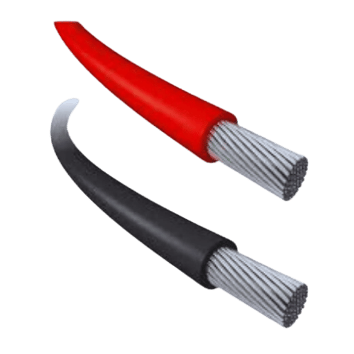
A 4mm solar cable capacity varies based on its insulation type, environmental temperature, and the way it is installed. However, in the most common case where there is enough ventilation and the temperature is approximately 30°C, the cable can carry between 20 and 30 amps; this range is very crucial in the solar photovoltaic industry. However, compliance and performance characteristics should be confirmed by the manufacturer’s specs along with local electrical codes, especially for single-core solar cables designed for domestic use.
Understanding the Current Capacity of a 4mm Cable
Factors like the type of insulation, installation conditions, and even the environment’s temperature affect the current carrying capacity of a 4 mm cable. Under normal conditions, and provided that the maximum allowable temperature of 30 is reached while taking proper ventilation into account, a 4 mm conducting cable would be expected to carry an electric load varying between 20 to 30 amps. When doing the installation, always follow the manufacturer’s instructions and local electrical codes to guarantee the proper operation of the equipment.
Factors Affecting Ampacity in Solar Installations
Changes in Temperature Variations of the Environment
As you may know, a certain temperature range is necessary for the efficient running of a cable. Such is the case with the ambient temperature, which greatly affects the electricity-carrying capacity of a single-core cable assembly. In retrospect, it is important to understand that a stronger ambient environment increases the ampacity. An insulation material, along with a conductor, is already subjected to an excessive temperature to enhance its resistance. For example, the cable used in repetitively used solar systems located in the deserts needs to have adjustment factors since the temperature can go beyond 40oC. If we talk about the standard IEC 60364, then in most cases, it is specified that when the temperature is greater than 30 C for every 10-degree rise, the ampacity level is required to drop by 10 to 20 percent with regards to the insulation type and method used.
Types of Cable Insulations
Apart from temperature tolerance limits that cable insulation can withstand, there are also designated limits for how much current can be used without damaging the insulation. For example, XLPE insulated cables can maintain much higher current levels than PVC insulated cables due to their increased heat tolerance. The cables that XLPE produces can work at high levels of 90 and, for short durations, raise the temperature level to 250oC, allowing greater tolerance for stronger environments.
Cable Installation Method
Under free air, heat dissipation is plausible, hence increasing the current capacities, unlike buried underground or conduits that restrict airflow. The installation of cables also determines the ampacity. For instance, the environment where the cable is to be surface mounted or buried plays a pivotal role in setting the cable’s ampacity. In the case of buried cables, the soil’s thermal resistivity becomes a determining factor, too; dry sand, for instance, is high on thermal resistivity, meaning that it worsens cable heat buildup.
Cable Length and Voltage Drop
In solar installations, long cables tend to introduce a voltage drop, which ultimately reduces system efficiency and increases the heat on the cables. Factors such as cable cross-sectional area, material, and length impact voltage drop greatly, too. For instance, a 4mm squared copper cable can achieve a voltage drop of approximately 1.15 percent while operating at 30 amps and 12 volts DC while running a distance of 100 meters as a common practice. Increasing cable size will solve the issue of voltage drop.
Conductor Material
The type of copper and aluminum also has an impact on the ampacity of the wire. Aluminum is less expensive and considerably lighter.A 4mm^2 copper wire has a higher current capacity than an equivalent aluminum wire under the same conditions, but on the other hand, copper wires tend to be the most preferred in solar installation due to their reliability and conductivity.
Multiple Cable Bundling
The bundling of multiple cables together interferes with the heat dissipation of the wires, leading to a lower ampacity. Many of the standards require the use of correction factors to ensure the safe operation of cable bundles. For instance, consider the use of four cables that are used together. The bolt required may be reduced by up to 40 percent; hence, there is a need to re-evaluate the system’s design parameters.
These solar system factors are also important to consider when designing and choosing cable systems for an installation. In addition to following the local and global laws, appropriately moderating multiple parameters can help guarantee a system’s optimal efficiency, safety, and life span.
How Insulation and Installation Impact Ampacity
The thermal capacity of a cable is largely influenced by the insulation materials, with PVC, EPR, and XLPE differing in its capacity to withstand heat. These materials have a distinct temperature threshold that restricts a cable to not exceed. For example, wires insulated with PVC have a threshold of roughly 75°C, whereas wires insulated with XLPE can surpass the threshold of up to 90°C. Due to the insulating properties of the insulated wires, XLPE insulated wires are more functional in conditions where higher heat is present or in environments where higher current loads are in practice.
Additionally, the insulation properties of a wire affect its ability to dissipate heat. Take, for example, the wires with a higher temperature capacity: if all external environmental factors are taken care of when using a single-core solar cable, then its capacity to dissipate heat could be increased.
How Does Voltage Impact a 4mm Solar Cable‘s Performance?
The Role of Voltage Drop in Solar Power Systems
The efficiency and quality of solar power systems are of pivotal importance, and this is best exemplified by voltage drop. The translation of electrical energy through a wire over a distance tends to most often lead to a loss of energy in its heat form which is commonly known as thermal loss. This phenomenon becomes especially significant in low-voltage systems such as residential solar installations, where even a slight voltage drop can result in measurable power losses.
The depth of a voltage drop is determined by several factors, such as the length of the cable, the cross-sectional area, the amount of current, and the conductivity of the material, which are all crucial to a specific type of cable. For example, a copper-based 4mm solar cable which possesses great conductivity typically has a higher voltage drop than aluminum cables of equal measurement, however, this does not apply in all situations. As wind load shear increases, so does the voltage drop. For instance, bodied solar arrays positioned in columns are more prone to greater shear than their horizontally stacked counterparts, which have a proximal force.
The recommended maximum voltage drop is 2-3% of the system’s mean voltage. If we use Ohm’sLaw calculations, a voltage drop of close to 0.5V can be expected for a 12V system which draws a 20 Amp current through a 4 mm2 copper wire over a 20m (i.e., a 10 mone way cable and a ten-meter return) distance. Loss would turn out to be slightly more than 4.2%. This is way above the maximum recommendable range. Such a voltage drop must cause us to either shorten the cable length, increase the size of the cable while compensating for the increased weight of the wire, or find efficient wire types that minimize losses.
Meanwhile, inverters that are meant for use in conjunction with PV solar systems have a certain voltage reach within which they are said to be most efficient. If the operating voltage drops abnormally low, the module may be unable to power the inverter, which reduces the energy produced and also the extent to which the energy was meant to work, and some inverters tend not to start at all. Consideration must be given to the size and types of the solar cables used alongside the efficient design of the entire system so that voltage drop is kept at the lowest possible level, thereby enhancing the overall energy returned by the solar array.
Calculating Voltage and Cable Length for Efficiency
To begin figuring out how much voltage and how long of a cable I will need to maximize efficiency, I will start by taking measurements of the total system voltage and current, from there. Using Ohm’s law and the formula I-V=R, I-V=R, with R being the resistance per length unit of the wire, I can get a fair estimation of the voltage loss when a current is present. With this, I would choose the cross-sectional area of the cable so that the losses are minimal while taking into account the whole distance from the solar panels to the inverter. Once I have made sure that the voltage loss is kept within a tolerable range, most usually under 3%, I can easily boost the system’s efficiency and performance.
What Factors to Consider When Choosing Between 4mm or 6mm Cable?
Comparing four mm² and 6mm Conductor Sizes
In my endeavor to compare four mm² and six mm² conduits, I would analyze if the current carrying capacity, voltage drop, and cost of a conduit contribute equally. I have realized that a six mm² cable is usually more costly compared to 4mm². However, it allows for higher amperage and is more suited for longer-range placements where energy wastage minimization is necessary. On the other hand, for systems requiring less current and shorter distances, four mm² tends to be more practical. In conclusion, I am more inclined to analyze such factors in combination with the solar installation requirements.
Impact of Ambient Temperature on Current-Carrying Capacity
The space temperature is one of the most important factors influencing a cable’s current rating, also referred to as its ampacity. Other factors such as resistance and heat generation could progressively decrease the ability of a cable to carry an electrical voltage if temps rise quite dramatically. Testing data also indicates that nominal ampacity ratings for cables are often provided at 30 degrees. Still, the opposite is valid on one of these bases as the material ampacity decreases by 10 or 20 underwater for every 10-degree rise above the 30 degrees above.
To elaborate, a copper cable with PVC insulation has C-PVC construction and cost ampacity ratings of 47 and 6mm3 which translates to 39 amps at 50 degrees in environments with heightened temperatures. Likewise, high terrains 50 degrees need D rating factors to be utilized. For locations with 40 to 50 degrees Celsius built, C5A8 has to keenly apply derating values of 0.87 and 0.79, respectively, to IEC 60287 benchmarks. The overheating of a cable could result in the insulation or other materials crumbling, to prevent this it’s useful to apply reduced values.
XLPE-type cables are made to work in high-temperature resistance, and to avoid these consequences, it is recommended that cables with better thermal performance insulation be applied. Also, oversized cables or ventilation can contribute to adequate current flow during high-temperature conditions. All of these factors are important in maintaining the safety, reliability, and efficiency of electrical installations.
How Cable Manufacturer Specifications Influence Choice
The metrics used for the cables play an important role in the final decision-making, as cable specifications offer important technical information. Manufacturers will often provide specifications for conductor material, insulation, temperature ratings and mechanical strength, to name a few. For example, insulation material exceeds temperature limitations set by PVC insulation, which is about 70 degrees; silicone rubber and XLPE Cross cross-linked polyethylene are rated for 90 degrees or even higher.
Electrical datasheets uploaded by manufacturers specify ampacity, sometimes referred to as how much current the cables can carry. This information is also provided alongside factors of conductor size, type of insulation and installation conditions. A 10 AWG copper wire is rated at 40 amps for safe usage under open air conditions, however if the wire used is insulated with PVC, then the safe limit drops down to 30 amps, this occurs as PVC has a lower heat resistance. These examples simply showcase how insulation material affects real-life performance.
Other important specifications for cables include waterproofing, enhanced chemical durability, UV resistance, and ingress protection. As an example, IP68-rated cables are rated with high standards, allowing safe usage in high moisture conditions, and are suitable for submersion.
Another major consideration is adherence to standards. Quality manufacturers make certain that their cables comply with such international standards as IEC, UL, and BS. As an illustration, all cables that are labeled as satisfying the IEC 60332-1 standard, for instance, are flame retarded, assuring adequate fire safety in installations where there are clear fire hazard control requirements.
Taking such parameters into account enables engineers and technicians to choose cables that meet the specific requirements of design so as to reduce the likelihood of failure and to maintain long term performance and regulatory adherence. Such data-driven conclusions are useful when it comes to ensuring operational effectiveness as well as the safety of electric systems.
What is the Maximum Current a 4mm Cable Can Handle?
Determining Maximum Current for Solar Photovoltaic Systems
For a four mm² cable, the maximum current capacity strongly depends on the cable construction, installation environment, and temperature around it. In most cases, however, a common 4mm² copper cable reliably installs for roughly between 25 and 32 amperes within a solar photovoltaic setup. Still, it’s imperative first to read the manufacturer’s manual or follow an applicable set of standards, such as NEC or IEC, to figure out the actual parametric value in hands. In this manner, one can prevent damage due to excess temperature from the hot cables and make sure the system works efficiently.
Ensuring Cable Safety and Efficiency in High Current Situations
In situations with high amounts of current flowing, it is vital to choose the right cable in order to maximize efficiency and minimize hazards to the system. Always pick a cable that is rated equal to or greater than the current rating of the system. Other than the mentioned parameters, heed the ambient temperature and environment while checking the cable’s rated value through trusted parameters such as the NEC or IEC. Insulation in adequate quantities and periodic checks are also needed to avoid overheating or damage to the equipment. Using wires with some safety factors for the current rating increases the reliability and efficiency of the operation.
How Does Cable Length Affect a 4mm Solar Cable‘s Amp Capacity?
Understanding the Impact of Cable Run on Ampacity
Ampacity is directly related to the geometry of the cable since an increase in the length leads to an increase in voltage drop. As the length of the cable increases, so does the internal resistance of the cable, which causes an increase in energy dissipation. The solar 4mm cable has a reduced ampacity, which is distance-dependent and can contribute to excessive energy being dissipated through heat when running over longer distances. In order to reduce this effect, it is important to determine the actual voltage drop concerning the length of the cable and keep it under certain limits according to the application, and in most cases, this voltage drop is less than 3 percent. Employing shorter runs or cables of larger cross-sectional area will improve ampacity and thus reduce the losses. Consult manufacturer parameters or other recognized standards for the maximum allowable length for the specific use.
Techniques to Reduce the Cable’s Ampacity Reduction
To counter the effect of ampacity reduction for a 4mm solar cable, a plethora of technical solutions are available to enhance the efficiency and performance:
Employ Larger Cables
Wider cables enable a greater level of current to flow through them due to reduced resistance. For example, suppose a 4mm Wide cable is switched to a 10mm wide one. In that case, the efficiency of ampacity is noticeably larger for greater distances as more heat can be dissipated. This is perfect for prospects with lengthier cable installations.
Reduce the Length of Cable Runs
Voltage deficits and resistance can be greatly reduced by trimming the physical length of the cable. For example, locating the power source closer to the load can dramatically boost the performance of the solar cables. Some studies suggest keeping the run for a 4mm solar cable under 10 meters to avoid exceeding 3% of voltage drop and maximize efficiency.
Choose Materials that are Good Conductors
Due to their low electrical conductivity, copper or tinned copper cables are much more efficient in transferring current than aluminum cables. Following the logic, replacing aluminum with copper can significantly decrease the issues with conductivity endurance due to copper being over 60% more efficient.
Make use of Parallel Cable Configurations.
Incorporating parallel cables splits the current into separate branches, thus reducing the current in each cable type. This technique should lower the current for each cable by half in the case of a two-parallel arrangement and, as a consequence, reduce heating and protect the performance of the components.
Maintain Adequate Cable Installation Procedures.
Preventing tightly packed cable bundles and poorly ventilated arrangements should mitigate overheating and excessive resistance. Similarly, cable management should be practiced; cables should not be bundled too close to each other, and appropriate conduits should be used. This reduces temperature within the permissible level conditions set by the manufacturer.
Evaluate Changes to Voltage Level.
A higher system voltage permits the lowering of the current without changing the amount of power to be supplied. Using the same 12 Volt example, if the system is doubled to 24 volts or 48 volts, the required current is also halved or quartered, respectively, which reduces the electrical losses across the cable over the same distance.
Practical Data Example
At an estimated temperature of 30 °C, a 4mm squared copper solar wire is said to have an ampacity of 36 Amperes when used in a 10m cable. In situations when the cable length is boosted to 30m, then due to the voltage drop occurring over the extended length, the cable’s effective ampacity may fall to over 20%. In the absence of mitigation strategies, these cases remain troublesome. However, if the same scenario is applied this time with a 6mm cable, the voltage drop is lowered to reasonable values while restoring power system efficiency.
When these procedures are applied, system developers can maximize performance, enhance the durability of cables, and guarantee the delivery of solar energy to homes and businesses without any errors. Risk evaluation scenarios followed by adherence to applicable electrical codes should always be considered.
Frequently Asked Questions (FAQs)
Q: What is the maximum ampacity of a 4mm solar cable?
A: It is estimated that a 4mm solar cable can operate between 30-40 amps based on installation conditions, ambient temperature, and insulation. Under ideal conditions, 4mm solar cables can carry a maximum of 30 to 35 amps for 12V systems.
Q: What are some restrictions that reduce the current carrying capacity of a 4mm solar cable?
A: Ambient Temperature, installation mediums such as conduit or free air, insulation material such as PVC or XLPE, and the system’s voltage ratings are only some of the factors affecting a 4mm cable’s ability to carry current. Enclosed cables or those used in higher-temperature installations tend to have lower current-carrying abilities.
Q: Are 4mm solar cables widely utilized in residential and small-scale commercial solar installations?
A: Yes, 4mm solar cables are often used in residential solar installations and small-scale commercial projects. These cables are optimal for linking solar panels to inverters in medium-powered systems. Still, the installation’s specifics must be considered stress-free of range constraints between components.
Q: What role does cable size play in achieving maximum solar PV system performance?
A: The cable size correlates strongly with the solar PV system performance. The system efficiency can be increased by making use of a larger solar cable, such as a 4 mm solar cable, which minimizes power losses, voltage drop, and power losses over a wide area. The increase in cable size aids the inverter’s performance as more power produced by solar panels is transferred to the inverter.
Q: How does XLPE compare to PVC when used as insulation in solar cables?
A: Cross-Linked Polyethylene (XLPE) and Polyvinyl Chloride (PVC) are two commonly used insulation materials for solar cables and wires. According to industry estimates, XLPE has better high-temperature performance and greater current tolerance than PVC-coated cables. Thus, under the same operating temperature conditions, a solar-sized four-millimeter cable insulated with cross-linked polyethylene XLPE solar cables can carry greater amps than one wrapped with PVC.
Q: Is using a 4mm solar cable with 12V systems okay?
A: Well, you could, but only if your 12V system is somewhat small or mid-sized. However, note that there are requirements regarding the cables being used. These are as follows: The voltage rating of the designed system should always match the envelope on the cables for overheating prevention or any potential safety issue.
Q: How can we tell if the 4mm solar cable installed suits the installation?
A: Well, first, the system has to be recorded in order to see how far its amp rating is from the established limit, and along the way, you will need to take into calculation voltage drop, ambient temperature, and even the method of installation used. If there is a larger value than the 4mm cable safety rating, you might need to reduce the length of the components or even replace the wire used.
Q: What happens if a cable smaller than the required size is used in a solar installation?
A: Normal application of a smaller than required cable, such as a 4mm solar cable in a high current application, would lead to a number of issues, such as excessive voltage drop, reduced system efficiency, and overheating of the cable, which can cause melting of insulation which can pose a fire risk and possible failure of the system. Always ensure that the cable size is equal to or greater than the requirements of the system.
Q: Is there something special to note about 4mm solar cables used in outdoor installations?
A: Yes, when using 4mm solar cables in outdoor installations, please check and make sure they are rated for UV exposure as prolonged exposure to sun might cause damage to the cables. Similarly, note that the temperature rating of the cables in outdoor environments tends to vary widely and swiftly. Utilize suitable cable management aids to shield the cable from the risk of mechanical damage and verify that relevant connections are tightened sufficiently to avoid leakage.
Reference Sources
1. Offshore Wind Farms Application- Efficient Use of Conductors Capacity
- Authors: M. Høyer-Hansen et al.
- 2022
- Overview: This examines a specific area of marine construction, namely, the offshore wind, and studies its offshore wind farms cable inter-arrays systems while aiming to improve the accuracy of cable ampacity calculations. While using finite element methods (FEM) for a three core over 20 kilovolts (KV) high voltage (HV) cable located in a J-tube, the study’s results indicated that adaptable model coefficient inclusion with the aid of solar influx in models led to much higher maximum temperatures, whereas solar influx wasn’t constant. By modeling wind speeds to measuring 20 m/s and modifying the heat transfer coefficient accordingly, an 18-degree Celsius dip from the steady state of a core cable’s temperature was obtained. Admissible current, on the other hand, increased drastically by 17%.(Høyer-Hansen et al. 2022)
2. Modelling the solar radiation thermal impact on the ampacity of low voltage underground cable.
- Authors: D. Klimenta et al.
- Published: 2018
- Summary: This paper investigates the impact of solar radiation heating on the ampacity of low-voltage underground cables. It argues that solar radiation should also be considered while estimating the cable system’s thermal requirements. The paper illustrates that temperature and other ambient conditions can considerably influence cable performance(Klimenta et al., 2018).
3. Ampacity of power cables exposed to solar radiation – recommendations of standards vs. CFD simulations
- Authors: Czapp, S. et al.
- Published: 2018
- Summary: The focus of this study is to assess the difference between the ampacity calculations for power cables subjected to solar radiation according to international codes along with CFD models. It outlines the differences noticed between standard recommendations and more complex simulations accounting for various environmental factors affecting cable performance (Czapp et al., 2018, p. 03004).
4. Underground Cable Sizing of Solar PV Power Plant: A Case Study
- Authors: C. Bates, P. Sen
- Published: 2019
- Summary: This particular case study investigates the cable dimensions of a solar PV power plant, taking temperature readings at several intervals throughout the year, which in turn helps to design the cable for optimum thermal performance. In the end, it highlights the fact that soil thermal resistivity is often mistakenly constructed and accurately impacts the soil thermal balance and the cable sizing(Bates & Sen, 2019, pp. 1–7).
5. ETERS2539: Underground Cable Trenches with Lining Materials’ Influence on the ampacity of Wind and Solar Farms Underground Cables
- Authors: E. Enrique et al.
- Published: 2019
- Summary: This paper introduces an approach to determining the ampacity loss of cable feeders when trenches are buried to hold cables used in wind and solar systems (Enrique et al. 2015: 1–8). This loss relates to the thermal resistance disturbance caused by the presence of insulating liners and the performance of cables.
Primary Observations and Techniques
Techniques: These reports mainly incorporate the application of the finite element method alongside computer-aided fluid dynamics (FEM and CAD) and some physical tests for determining the impact of temperature exposure on cable ampacity. They further emphasize the differences between the customary calculation procedures and simulations and aim at accuracy enhancement.
Primary Observations:
- Environmental conditions, such as solar radiation and wind speed, are key determinants of the ampacity of power cables, along with other interventions.
- Improved ampacity assessment may lead to enlarged permissible current and/or minimization of the cable’s cross-section sizes, thus reducing installation costs.
- The lining material in the trenches will likely change the thermal properties of the underground cables and should be measured accordingly in the design process.
Get Your Solar Cable Needs Covered with JOCA – Your Trusted Supplier