Recognizing 7-pin trailer wiring diagrams is crucial for all levels of towing expertise. Whether you are a veteran hauler or just getting to grips with trailer setup, these diagrams act as a guide for proper towing standards where safety and functionality are crucial. This guide aims to dismantle all 7-pin wiring system intricacies and align step by step to every skill level. We will ensure that your brakes work, your trailer lights shine bright, and that all of your towing worries, twining kerfuffle-free, are easy to navigate around with. After this article, you will not only comprehend 7-pin trailer wiring intricacies but also energetically troubleshoot or install a system all on your own.
What is a 7-way trailer wiring diagram?
A 7-way trailer wiring diagram displays the connections needed for an industry standard 7 pin trailer wiring system. This diagram shows how each pin in the connector is assigned specific functions, like powering the trailer lights, brakes, turn signals, and auxiliary systems. Seven pins are usually included with dedicated lines for the left turn signal, right turn signal, brake lights, tail/running lights, electric brakes, reverse lights, and a 12V auxiliary power. Users are guided so they may appropriately wire their trailers to enable safe and reliable towing operation.
Understanding the 7-pin trailer setup
Correct pin wiring on the 7-pin trailer plug will facilitate interaction between the towing vehicle and the trailer. Each pin, for instance, controls its own individual function, such as lights, brakes, and power. Safe towing practices require these signals and systems to be correctly enhanced, optimising safety. Warnings indicators deploy when the vehicle is misaligned with standards, which illustrates the importance of ensuring wiring is done right without risk of failures.
Components of a Trailer Wiring Diagram
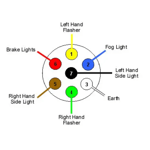
Usually, such schematic diagrams contain a description of each connector pin in relation to the function given to it within the 7-pin trailer connector. Below is the standard diagram along with the components it is made from:
For White Wire Ground:
This wire is crucial in ensuring compliance with the trailer light wiring.
The ground wire links the vehicle with the trailer electronically; it provides a stable point or reference level for voltage. Stability is essential along with electrical safety within the system loop.
Brown Wire Tail Lights and Marker Lights:
Nor any low light conditions may hinder the visibility of the trailer, these ensure that the trailer is in full view at all given times especially during the night. road safety compliance requires these lights to work optimally.
Yellow Wire Left Turn Signal and Brake Light:
This wire initiates the function of the Left turn indicator and the brake light on the left side. The signal should get executed to turn smoothly without endangering safety.
Green Wire, Right Turn Signal, and Brake Light
As with the left side, the right pin also delivers designation during stop and right turn signal lights. Clear, responsive lighting is essential to maintain safe signals on the road.
Blue Trailer Brake Controller
Used for the powerful electric brakes on the trailer, this wire works for enhancing stopping power and better control during tow about the grade. This is especially important during sudden stops or when moving downhill.
Battery Charge/Auxiliary Power (Black/Red)
The auxiliary power wire provides energy to the trailer battery while driving or powers onboard lighting or cabin appliances.
Reverse Lights (Purple)
Reverse light functionality facilitates enhanced visibility when reversing the trailer, improving safety during parking or in confined space navigation.
Each connection needs to be checked carefully in order to operate properly and prevent dangers while towing. Installation is simplified due to the provided color codes, eliminating possible wiring mistakes. Damage from the environment or wear and tear over time is best prevented by using waterproof connectors, secured parts.
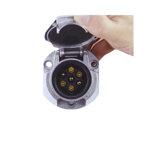
The role of a trailer plug in the wiring system
The trailer plug is a vital component of the interface between the towing vehicle and the trailer because it permits the transfer of electricity for various systems such as brake lights, turn signal lights, tail lights, reverse lights, and even auxiliary power or electric brakes where applicable.
The trailer plug has many configurations, with the 7-pin connector being the most versatile. For example, a 7-pin trailer plug supports lighting and energizes braking systems applied to the trailer as well as internal batteries fitted within the trailer. These features improve safety and operational efficiency when towing.
Current developments regarding trailer plugs emphasize their strength and resistance to weather conditions. The use of electrical connections composed of protective metals and durable plastics that resist corrosion will ensure that the connections are protected from the environment. In addition, with proper maintenance, trailer connectors allow for around 25 percent reduction in electrical faults, improving reliability when towing trailers. Since secure connections and proper attention help extend the life of trailer plugs, a suitable focus on them can prevent electrical failures during movement.
How to wire a 7-way trailer?

Step-by-step trailer wiring installation guide
Obtain Necessary Equipment and Supplies
Before you begin, check that you have a 7-way trailer plug, a wiring harness, wire strippers, electrical tape, connectors, as well as a voltage tester. Use weatherproof connectors and high-grade wiring to enhance durability and hinder corrosion.
Know the 7-Way Wiring Diagram
Get accustomed to the basic 7-way trailer wiring color code where ground wire is white, left turn/brake is yellow, right turn/brake is green, tail/markers brown, electric brakes blue, auxiliary power black, and reverse lights purple. Knowing this layout is critical for proper installation.
Disconnect the Battery
To enhance safety from electrical short circuits, it is advisable to disconnect the vehicle’s battery before starting the RV trailer wiring.
Trim Wires
Using wire strippers, remove the insulation on the end of each wire to reveal the copper. Do not strip more than 1/4 inch. Stripping more than necessary increases the risk of short circuits where two exposed wires touch.
Connect the Wires to The Trailer Plug.
Start attaching the wires to the appropriate terminals on the trailer plug as per the diagram. Each wire must to be secured properly, and cross check the connections to all of them. A loose connection can cause lights to blink or not function properly.
Secure the Wiring Harness for the trailer light Wiring.
Position the wiring harness along the trailer frame and bind it with cable ties or clamps at regular points. Make certain that the wires are not hanging freely or placed in high movement or heat risque areas which could lead to destruction.
Test the Connections
After using the voltage tester or a trailer tester ensure that every electrical function is operating accurately, ensure the vehicle’s battery is reconnect. They include brake lights, indicators, tail lights and additional power. Ensure to carry out testing to ascertain that safe and reliable operation when towing with your trailer hitch.
Seal and secure the connections.
To improve the protection against dirt and moisture seal all the connections with electrical tape or use heat shrink tubing. Following these steps will improve the durability and life span of the wiring systems of the trailer.
Carry Out Routine Maintenance
To sustain the functionality and safety of the trailer wiring, check each connection for damage or corrosion periodically. Routine checks will most likely pinpoint any problems before they worsen.
Following these procedures will help you implement a dependable and effective 7-way trailer wiring setup. Best practices during installation greatly reduce the probability of electrical malfunction while towing, as well as, aid compliance with safety standards.
Choosing the right wiring harness
Choosing the right wiring harness is one of the most important steps you will take toward optimizing the safety and efficiency of the electrical system of your trailer. The choice is influenced by multiple considerations such as the vehicle make, the towing capacity, and the trailer’s electrical needs. While standard wiring harnesses are built to accommodate the rudimentary towing tasks, advanced units come fully equipped with circuit protection, automated brake controls, and features that make them suitable for heavy-duty operations.
While selecting a wiring harness, a few important specifications should be kept in mind:
Compatibility With the Vehicle’s Make and Model
Custom molds abound for the various brands and models of vehicles, so most of the harnesses you come across will cater to a particular brand or model. Ensuring functional compatibility avoids installation issues and makes certain that trailer lights and signals operate as intended. For example, harnesses equipped with plug and play features alleviate setup headaches thus rendering quick configuration.
Gauge and Material Quality
The diameter of a wire defines its gauge. Lighter trailers with more electrical load need higher gauge wires to reduce the possibility of overheating. Seek out harnesses constructed from copper with PVC coatings, as these materials provide added resistance to corrosion which guarantees dependability over time.
Power Output and Circuit Protection
Be certain to check the maximum power output the harness can handle. More advanced models may offer integrated circuit protection such as fuses or relays designed to protect against powered surges. This is particularly helpful for reducing damage to a vehicle’s and trailer’s electrical systems when they are in operation.
Waterproofing and Durability
Trailers are often subjected to harsh external weather. Look for wiring harnesses with waterproof cutouts and encapsulated wiring to protect against water, dust, and debris. Products with a high IP (Ingress Protection) rating are best suited for performance in extreme conditions.
Brake Controller Integration
Most modern harnesses now include provisions for towing brake controllers for the convenience of users. This increases safety by allowing precise control over the brakes, particularly when a heavy load is being towed.
High-quality wiring harnesses can reduce the rate of electrical failures by over 60%. This prevents the owner from spending on expensive repairs in the long run. Investing in a quality harness ensures performance, reliability, and safety and considers economical goals for towing equipment.
Troubleshooting common wiring installation issues
In towing operations, a setup with a properly fitted harness guarantees functionality and safety. The list provided below cites the most common issues experienced during wiring installations as well as their potential causes and solutions:
Terminals And Connections That Are Loose Or Defective
- Cause: Failure to sufficiently secure fastening, inscribe terminal connections, and strike crimp contact could lead to loose connections.
- Solution: Every applicable connection, especially those affixed with crimp tools, ought to be fastened. Always use quality crimp tools. Terminals and connectors showing signs of damage must be inspected and maintained in working order.
Loss of Voltage or Power
- Cause: Damage to wiring, use of improper wire gauge, corrosion on connection points.
- Solution: Ensure cables are securely fastened and if possible, use protective measures like heat-shrink tubing and dielectric grease on the wire. Also, make certain that the gauge and mesh of the wire align with the power requirements.
Fuses That Are Blown
- Cause: Short circuits as a result of loose protective covering on wires or routing wire too close to sharp objects.
- Solution: Protective coverings should be used around loose wires, and all other damage should be inspected. Collision with sharp areas, along with high-temperature site,s should not be permitted.
Issues Contained In The Ground
- Cause: The origin of fallacious electrical movement should reasonably be traced back to weak or insufficient grounding.
- Solution: The gap where wires link to the earthing layer should be cut and have clean anchorage. Rust and paint at the location where the shore contacts should be eliminated for proper contact to be firmly secured.
Erratic Signal Transmission
- Cause: Crossed and incorrectly connected wires at the junction points.
- Solution: Reconfirm all wiring connections against the schematic of your vehicle’s wiring system. Use continuity tests to rectify discrepancies.
Wire Overheating
- Cause: Incorrect or excessive current draw due to poor heat dissipation.
- Solution: Ensure the schematic of the circuit does not exceed the load threshold of your RV plug. Replace the damaged wires then insulate thermally or add venting to regions that are susceptible to overheating.
Periodic Electrical Functionality
- Cause: A combination of loose connections from wear and tear coupled with vibrations from components over time.
- Solution: Routinely check the wiring and connectors for any signs of wear and tear. Support the wiring with vibration mounts or clips.
Preventive action and regular upkeep of these highlighted problems can vastly mitigate the chances of electrical failures. Proper installations of the wiring help in improving not just performance but the safety of the towing systems as well.
What is the purpose of trailer plug wiring?

Ensuring proper vehicle wiring connectivity
Well-organized vehicle wiring connections guarantee that the electrical systems of the towing vehicle and the trailer interface appropriately: the lights, brake lights, and turn signals are powered using a 4 way connector, which is necessary for both functionality and safety for driving compliance. With proper tailored wiring, operational and reliable wiring ensures performance accuracy during towing operations.
The importance of trailer light functionality
Operating trailer lights, like markers, brake lights, turning signals, and tail lights, is crucial when towing a trailer since they help alert drivers of other vehicles about its presence. Proper functioning trailer lights also assist drivers who operate vehicles during night or in low-light conditions to reduce accidents. Of course, proper marking and illuminating lights are legally required by the law in many places. Compliance with maintenance check rules is required to ensure proper maintenance of the lights on the trailer. Regular examinations and maintenance checks are required to ensure the proper functionality of the trailer.
How to maintain your trailer wiring harness
Proper maintenance of your trailer’s wiring harness is essential for reliable operation while towing. Start by conducting regular inspections looking for any signs of wear like fraying wires, corrosion, or cracked insulation. Safety and functional balance relies upon a fully intact electrical system which necessitates the prompt repair or replacement of compromised wires.
Clean all connections to assure they are tight and free of dirt, moisture, or road debris, as these can lower the conductivity of the trailer light wiring. Clean the contacts with soft bristle brushes and cleaners, then secure strong connections using dielectric grease. Make certain that the corrosion preventative is placed on the pins and sockets of the connectors, as they are vital to proper signal transmission.
Correct routing, along with securing the mounting of the harnes, also requires consideration. Over ti, me damaging encirclement of wiring is a problem that arises from loose wires being pinched and tangled. Make use of cable ties, along with clips, to secure the harness to the trailer frame without having the straps placed in areas where excessive movement will occur.
Be sure to regularly use a multimeter or specialized trailer tester to check the trailer wiring harness for proper voltage output to the stages of the trailer lights, which include brake lights, tail lights, and turn signals. In most light-duty trailers, the voltage should be approximately 12 volts. If there are any issues, identify the cause, which may include loose connections, broken wires, or blown fuses.
Above all, ensure fully covering the trailer wiring harness post ride with components plugs to prevent environmental wear. Store the plugs in a cool dry location to prevent wear and tear for added versitility. Following these tips should guarantee the optimal dependability of your trailer wiring harness for enduring a longer life span.
How do you identify wire colors in a 7-way connector?
Color coding in 7-way trailer systems
The 7-way connectors are used in various towing configurations that require a specific wiring trailer configuration. Each wire has a specific function, and color coding is crucial for accurate installation and troubleshooting. The following is an analysis of the standard color codes used for 7-way connectors.
Black Wire – Auxiliary Power
The black wire provides a 12V auxiliary output which powers devices like interior lights on the trailer or batteries during towing. Before using the black wire, verify its amperage capacity to confirm it meets the required standards.
Red Wire – Reverse Lights
The red wire is utilized to switch on the trailer’s reverse lights. The wire must connect into the reverse gear circuit of the tow vehicle so the lights can properly function during backing maneuvers with the 7-way connector.
Blue Wire – Electric Trailer Brakes
The blue wire that goes to the electric brakes of the trailer comes from the brake controller located in the towing car. Adjusting the controller for precision limits assures the equipment will be in safe condition during use.
Green Wire – Right Turn Signal and Brake Light
The green wire connects the right turn signal and brake light of the trailer to the tow vehicle. It allows for communication with other drivers on the road as the signaling system is synchronized with the vehicle’s signaling system.
Yellow Wire – Left Turn Signal and Brake Light
In the same manner as the green wire, the yellow wire integrates the left turn signal with the brake light. This enables the trailer to signal correctly to other drivers when turning or braking so proper warning is provided.
Brown Wire – Tail Lights and Running Lights
The brown wire supports the functioning of tail lights and running lights. It can ensure that the trailer can be seen during night driving or in low-light conditions such as dusk.
White Wire – Ground
The white wire is used as the ground wire for the entire system. For good performance, it must be connected securely to the frame of both the trailer and tow vehicle to create a circuit and result in a dependable bond.
Safely towing and avoiding mishaps require the wires to be connected accurately. Make sure to inspect the wiring of both the tow vehicle and the trailer; there will be discrepancies based on the type and model, so consult the manufacturer’s diagrams. Additionally, confirm that no wiring faults are using a multimeter to check voltage and continuity within specified limits.
Understanding wire color significance
Understanding the significance of colors in wires is critical to the functionality and safety of electric systems. The following is the meaning of each color:
- White: Represents the Ground connection, securely completing the circuit.
- Brown: Indicates the Tail lights and side marker lights function.
- Yellow: Denotes Left turn signals in conjunction with brake lights.
- Green: Symbolizes Right turn signals, as well as brake lights.
As with all illustrative materials, these codes should always be checked against the manufacturer’s documentation in case of discrepancy. Accurate wiring helps eliminate issues and guarantees that the system functions safely.
Customizing wire colors for specific needs
Personalizing wire colors can simplify complex wiring setups, enhance visibility, and increase maintenance effectiveness. Tailored wire color schemes may be needed in different projects and industries. In automotive applications, for instance, custom color coding helps troubleshoot problems more easily and lessens mistakes during assembly. In residential or commercial electrical work, it helps enhance safety and compliance with legal requirements.
New advancements in wire manufacturing offer new custom solutions such as UV cutting wires, which safeguard custom colored identification from outdoor exposure. Studies show that systems designed with standard, yet uniquely styled, custom-tailored wires have resulted in up to 30 percent reduced maintenance time. This efficiency allows the technician to more quickly isolate and resolve issues. When designing a color scheme, it is advisable to incorporate colored heat-shrink labels or printed markers to further reduce the chances of misinterpretation using the chosen colors. Always ensure the combinations of the customized wire colors are within local and industry regulations, such as NEC (National Electrical Code) recommendations, to uphold compliance and operational safety.
What are the benefits of using a 7-way trailer plug?
Advantages of 7-way RV blade connectors
Enhanced Functionality
The 7-way RV blade connector handles multiple auxiliary trailer functions, such as tail and brake lights, electric brakes, turn signals, reverse lights, auxiliary power, and ground wire connections. This ensures the proper functioning of advanced RVs and trailer units.
Standardized Design
The 7-way blade design is a standard solution in the industry; therefore, it is used in several cars and trailers. This standardization further enhances the simplicity of installation while minimizing the possibility of connection errors.
Durability and Weather Resistance
These connectors are manufactured using strong materials that can endure extreme environmental conditions such as rain, snow, and high levels of humidity. Many 7-way connectors encapsulate the electrical contacts within weatherproof casings, which guard them against corrosion and wear over time.
Improved Safety
The functionality of vital safety elements such as the trailer brakes and lights is guaranteed with dependable connections made possible by the 7-way blade design. Proper signaling and stopping are essential for avoiding accidents on the road.
Ease of Maintenance
The standard configuration along with the rugged design makes diagnosing and performing repairs easy and straightforward. Industry reports indicate that these efficiencies can reduce troubleshooting times by as much as 25%.
Support for High Electrical Loads
Due to its greater electrical load capabilities, the 7-way configuration is appropriate for trailers with numerous powered elements like refrigerators, air conditioning units, and sophisticated lighting fixtures.
Versatility for Modern Applications
As new trailers and RVs are introduced to the market, there is a greater need for multifunctional features. The 7-way RV blade connector accommodates auxiliary functions, such as backup cameras and charging systems, in addition to its traditional roles.
The 7-way RV blade connector effectively meets the electrical requirements of trailers and RVs, demonstrating reliability and long-term performance under varying conditions.
Compatibility with RVs and utility trailers
The 7-way RV blade connector is designed to match RVs and utility trailers on all levels. It facilitates the interconnection of towing vehicles and trailers to sustain constant energy flow to important systems. This connector enables the powering of vital systems like tail lights, brake lights, and turn signals, which are needed for safe and efficient towing operations.
The 7-way connectors are now standardized with the SAE J2863 standard, which is used mostly in North America so that it can be universally accepted and designed for many uses. Research shows that approximately 80% of new RVs and trailers coming out are equipped with this connection, which proves it’s accepted. The connector also accommodates 12-volt power supplies and auxiliary functions, thereby catering to different types of trailers ranging from small utility models to large fifth-wheel RVs.
The rugged structure of the connector allows it to perform reliably under different conditions, such as long road trips or extreme weather exposure. This universal compatibility and dependability reduce the need for extensive re-wiring or adapters with the 7-blade RV connector, which is why this feature is an essential component of modern towing gear.
Improving trailer brake performance
It is important to enhance safety and performance while towing with a 7-way connector, and it is critical to improve trailer brake performance. The integration of advanced brake controllers, like proportional or time-delayed systems, is one of the most effective approaches. Proportional brake controllers reduce the negative strain on brake system components by more smoothly mitigating deceleration through the adjustment of the trailer brake in proportion to the deceleration of the towing vehicle. Studies show that proportional systems, especially under heavy load conditions, can curb stopping distance by up to 25% relative to conventional setups.
Moreover, regular maintenance of the trailer brake system improves overall performance, longevity, and efficiency. This includes checking moving parts like brake pads, rotors, and drums for proper lubrication and attending to them if they exhibit signs of damage. Evidence suggests that insufficiently replaced worn brake pads can diminish braking efficiency by as much as 30%. In addition, optimizing the calibration of the sensitivity of the controller for the trailer brake is very important. This is because overly aggressive or feeble braking can affect the stability of the vehicle or lead to prolonged stopping times, respectively.
To improve reliability, most manufacturers suggest shifting to Electric Override Hydraulic (EOH) braking systems for fifth wheel configurations or heavier trailers. EOH systems integrate electric control and hydraulic brakes, and thus provide superior braking force and responsiveness. EOH systems have also been proven to reduce fade in stopping power during prolonged and steep braking which contributes to overall safety measures.
In addition, maintaining proper voltages to the wiring connections of the brake system ensures consistent performance. Faulty wiring and voltage drops can lead to pre-emptive and sporadic engagement of the brakes, increasing the distance required to come to a complete stop when the trailer is hitched. Ensuring the usage of good quality connectors prevents disruption of operations even in extreme environmental conditions, which contributes to better operational reliability.
Frequently Asked Questions (FAQs)

Q: What is a 7-pin trailer wiring diagram?
A: A 7 pin trailer wiring diagram is a type of schematic that indicates the pinout related to connecting the 7 wires from a vehicle to a trailer using a 7-way socket. It includes the running lights, electric brakes, and turn signals, as well as the ground wire. This diagram is critical for the wiring of a trailer to make sure that all trailer mounted lights and electric parts operate appropriately.
Q: What are the main components of a 7-way trailer connector?
A: A 7-way trailer connector usually contains pins for: left turn/brakes, right turn/brakes, taillight or running lights, electric brakes, 12V power for the trailer battery charging, reverse lights and ground wire. They provide good circuit for the vehicle and the trailer for safe towing.
Q: How to wire a trailer with a 7-pin plug.
A: IN Wiring a trailer with a 7 plug, you has should: 1) examine each wire and its relevant function in a wiring diagram. 2) Make the necessary connections between your vehicle’s systems and the 7-way plugs with proper pin assignments. 3) On the trailer side, simply plug into your vehicle’s existing system, such as brake lights and turn signals, to fire your vehicle’s parts. 4) Make sure the ground wire is well connected. 5) Recheck all connections to ensure you have done everything right before starting to tow.
Q: What is the difference between 7-way round and 7-way blade connectors?
A: The primary distinction between a 7-way round and a 7-way blade connector is their configuration. The 7-way round connection is circular in shape and has 6 wing pins surrounding the center pin, while the 7-way blade connector has a rectangular flat shape with 7 pins in a row. Both perform the same functions, but one without an adapter, can the two not be interchanged? The commoner type in newer vehicles and trailers is the blade style.
Q: Do I require a trailer brake controller for a 7-pin setup?
A: Yes, with a 7 pin setup, you will require a trailer brake controller if your trailer has electric brakes. A brake controller will manage the electric brake wire so that the appropriate braking force will be commanded on the trailer and, hence, allows selective braking. This is important for safe towing, particularly for heavier trailers. In the case where there are no electric brakes on the trailer, you may get away without a controller, but as always, check your local laws.
Q: How do I connect different types of trailer plugs using wiring adapters?
A: Different types of plugs can be connected using a wiring adapter to convert a 7-way connector to a 4 or 5-way plug. The use of an adapter is simple; all you have to do is plug it into your vehicle’s existing wiring and plug your trailer’s plug into the adapter. If you have a vehicle that tows different types of trailers, it is ideal for your wiring not to be changed. Remember that changing the adapter for the one used in your car or trailer is necessary.
Q: What should I do if my trailer lights do not work after the 7 pin plug was connected?
A: In cases where a 7-pin plug was connected and the trailer lights stopped working, try the following: 1. Inspect all custom wiring connections to ensure contact is made and is not corroded. 2. Confirm the ground wire is connected. 3. Make sure a multimeter confirms power in the vehicle’s wiring and that the power is at the plug in the vehicle. 4. Examine the fuses that may be associated with the wiring to the trailer. 5. Ensure the wiring in the trailer is intact and not broken. 6. If no solution is found, the recommendation is to call someone who is well-versed in the problem or check manuals for the trailer and vehicle for further reference.
Reference Sources
1. DRAFT: Bifurcation Analysis of Trailers: Numerical and Experimental Approaches
- Authors: Hanna Zs. Horvath
- Publication Year: 2020
- Key Findings: This work develops a 4-DoF spatial mechanical model of trailers to study the snaking, rocking, and rollover motions of trailers. It analyzes the governing equations and the non-smooth aspects of tire forces to uncover the stability characteristics of trailers under different operating conditions. The work is accompanied by simulations that capture the periodic solutions obtained through bifurcation analysis ― these are later verified numerically as part of the study.
- Methodology: The research uses bifurcation analysis in continuity with other simulations and analyses to capture subcritical oscillations at certain defined parameters within the nonlinear dynamics or stability threshold (Horvath, 2020).
2. Vehicle Linear And Rotational Acceleration, Velocity, And Displacement During Staged Rollover Collisions
- Authors: O. Keifer et al.
- Publication Year: 2007
- Key Findings: The study conducts staged tests to analyze vehicle rollovers, emphasizing linear and rotational acceleration. This work attempts to document vehicle responses in rollover situations, which is important for understanding trailer dynamics while towing.
- Methodology: The research included full-scale vehicle rollover tests using an array of accelerometers to monitor vehicle motion during rollovers (Keifer et al. 2007).