Using solar energy systems to capture energy from the sun is one of the greatest steps toward achieving sustainable and renewable energy solutions. These systems utilize important parts that guarantee smooth and reliable systems of energy transmission. Out of these parts, solar cables and connectors serve as the backbone for the safe and effective transfer of electricity harvested from solar panels. This article will focus on the basic appreciation of these components by clarifying their types, functionality, and scope to achieve optimized overall system performance. Whether you are an industry professional or just a homeowner weighing the prospects of solar energy, knowledge of solar cables and connectors is indispensable when making design and maintenance decisions for a reliable solar power system.
What are the Different Types of Solar Cable Used in Solar Power Systems?
Three categories of cables are usually used with solar power systems:
- PV (Photovoltaic) Cables: These cables are used for interconnecting solar panels to inverters. These cables are covered with strong plastic that protects against ultraviolet rays. These cables are also waterproof and can handle high temperatures.
- DC (Direct Current) Cables: These cables transport the current from the solar panel to the inverter. These cables are built to high voltage power and have low energy loss.
- AC (Alternating Current) Cables: These cables connect the output of the inverter to the electric grid or the electrical wiring of the building. These cables have insulation which provides extra protective covering and improves efficiency.
To achieve full functionality at the optimum voltage, using specialized solar cables is a must. Without them, electric faults and losses will be rampant.
How Do Solar Cables Differ from Traditional Wire?
The difference is that solar cables are designed and function for solar power systems, unlike the other types of wires. Unlike the other standard wires, solar cables have the ability to withstand constant exposure to ultraviolet rays, extreme weather conditions, and harsh environmental changes. They have a double layer of insulation, which helps to enhance durability, safety, and use, along with protecting against short circuits or wearing down over time. In addition to that, solar cables have a higher voltage and current capacity, which helps in effective electricity transmission within the solar system. Unlike traditional wires, solar cables have these characteristics, which make them tougher and fit for the distinctive needs of solar energy applications.
What is the Role of PV Cable in a Photovoltaic System?
PV cables, best known as photovoltaic cables, are designed to take care of specific and on-system affairs in a solar energy system. As such, they are primarily a means of conveying electricity in the form of direct current (DC) from the solar panels to the inverter for conversion into alternating current (AC) electricity (used in homes, industry, and business). Among the most important characteristics of PV cables are high resistance to heat (usually up to 90°C or more), UVand other weatherproof features which ensure better endurance over time under any exterior climate conditions.
One of the major elements of PV cables is the capacity to sustain unprecedented voltage levels, reaching 1,500V DC in modern solar systems, which is much higher than standard electrical cables. This characteristic has a great impact on solar installation’s efficiency and scalability, as they directly affect the amount of power received from the sun. Also, PV cables are made of flame retardant and halogen-free materials, which makes them safer in case of fire and compliant with international safety standards like IEC 62930.
Optimally choosing and installing photovoltaic (PV) cables reduces energy losses and system downtimes. For instance, reliable PV cables transmit energy at losses below 2%, which helps in maximizing the photovoltaic system’s energy output. Their durable construction enable them to survive for more than 25 years, which is often the operational life of solar panels. This reduces the replacement and maintenance requirements.
PV cables must also be designed and deployed in a way that supports the other components of Solar Systems. These cables ensure high transfer efficiency, and system reliability and safety, and therefore contribute to the proliferation of renewable energy technologies.
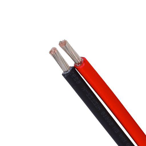
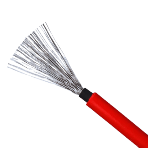
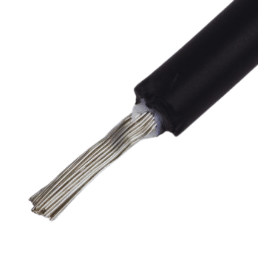
Why is Tinned Copper Preferred in Solar Cables?
In regards to solar cables, tinned copper is favored due to its electromagnetic shielding and corrosion resistance capabilities. Without the protective oxide layer, electric bare copper can corrode and oxidize when exposed to moisture, air, and other environmental elements, which minimizes the effectiveness of the cable and reduces its lifespan. Tinned Copper lasts much longer as the inner layer of tin maintains consistent conductivity and durability even in outdoor environments. Due to the extreme weather and solar conditions to which solar cables are subject, tinned copper is the best choice for solar cables.
How to Choose the Right Connector for Your Solar Panel?
What to Consider When Selecting a Solar Connector?
Choosing the right solar connector is imperative for maximizing function, efficiency, longevity, and safety in your power system. Consider the following key points:
Consider the Compatibility with Solar Panels and Cables
- Check that the connector is compatible with your solar panels and cables so that seamless integration can be achieved. Most solar panels incorporate MC4 connectors, which are widely used because they are user-friendly and easy to connect. Additionally, check the wire gauge and ensure that the connector’s size is adequate for your cables, which, in the case of solar applications, typically vary from 14 AWG to 10 AWG.
Examine the Current and Voltage Ratings
- Check that the connector is compatible with the solar panels and cables so that integration can be achieved. Most solar panels utilize MC4 connectors, which are widely used because they are user-friendly and easy to connect. Additionally, check the wire gauge and ensure that the connector’s size is suitable for your cables, which, in the case of solar applications, range from 14 AWG to 10 AWG.
Weather Conditions and Longevity
- The solar connectors for outdoor use must be designed to endure severe weather like ultraviolet rays, rainfall, and extreme temperatures. Check for connectors with an IP67 rating or comparable ratings that guarantee protection from dust and water. Even in harsh environments, the use of insulating materials like thermoplastics improves the connector’s durability.
Convenience in Configuration and Servicing
- The product’s design promotes ease of use during configuration and servicing. Numerous solar connectors come with a simple locking feature that guarantees both security and ease of disconnection during system alterations or inspections. Further, some tools are required like crimpers or specialized wrenches, so these must be present at the site during configuration.
Legality and Compliance
- Check that the solar connectors fulfill the minimum requirements of safety and performance, like UL 6703, IEC 62852 or TÜV certification. A certified component is guaranteed to have met the necessary test for reliability and safety under different operating environments so that you do not use inferior parts.
Performance Versus Cost Analysis
- Expenses will always influence decisions, but trying to achieve the lowest price possible may compromise quality and efficiency. Connectors that are more expensive to purchase may outperform their cheaper equivalents, offering higher savings in maintenance costs. Achieve reliability while still optimizing cost-effectiveness with the right strategy.
Your solar power system’s safety and performance can be guaranteed with quality connectors if these factors are evaluated. Properly selected connectors provide further benefits such as reduced energy losses, improved performance, and increased durability of the entire installation.
How Does MC4 Connector Enhance Efficiency?
By eliminating unnecessary energy losses and establishing a secure connection between solar panels and other system components, MC4 connectors improve the overall efficiency of the solar energy system. Their design enables a snug, waterproof seal that safeguards moisture and dust as environmental factors which can harm performance. Furthermore, MC4 connectors allow for fast and smooth plug-and-play installation which enables a reduced probability of mistakes that may decrease efficiency. All these features leads to greater reliabilty of the system as a whole and optimazed energy production.
How to Ensure Proper Installation of Connectors?
As a general rule, every component in a solar power system has to make use of the same design and specification in order to function properly. Below are procedures that guide the proper installation of connectors:
Use Appropriate Parts
- In other words, confirm that the connectors used are of the correct type, size, and rating with the cable being used. For instance, MC4 connectors work best with 4 mm square to 6 mm square cables. Components that are not correctly aligned can be a source of power loss or even compromise safety.
Prepare Cables Properly
- Cable insulation that needs to be removed comes with a set length (generally between 6 to 7mm), and it is best to make sure the strands of the conductor are not broken. Broken strands can make connectivity difficult and the possibility of increasing temperature too much.
Connector Crimping
- Use a unique crimping tool that is certified to fasten the connector pin firmly onto the cable. Do not use non-specific tools because many of them are not able to deliver the right amount of force, which tightens the connections and will result in loose junctions or arcing.
Ensure Polarity
- Confirm the polarity of the connectors and cables for the second time. Putting negative where positive is expected and vice versa will lead to system faults or deployable arms.
Final Tightening Steps
- Polarity checks are the last step before putting the cables to work and ensures that cables act the way they are supposed to at all times. So, your safety is backed by these mechanisms provided to guarantee sustain electric power grid efficiency.
Apply Proper Torque: Examine the Instructions
- To guarantee caps or locking mechanisms are waterproof and dustproof when MC4 connectors are used, a tightening torque of 2.5-3.0 Nm is specified to be used whilst tightening the connectors.
- Use a cap wrench to tighten the cap or locking mechanism with the indicated tightening torque of normally 2.5 – 3.0 Nm.
Inspect for Defects
- Evaluate the connecting components for external indications of deformation like cracks, breaks, or misalignment after assembly. Use of these connectors should not be allowed as they are deemed defective because they undermine the system integrity.
Perform Electrical Continuity Test Procedure
- Check for electrical connection continuity with a multimeter and check for minimal resistance in the joints as well. Elevated resistance values may suggest an incomplete or damaged connection.
Environmental Considerations
- Check that the entire area around the installation is tidy and not wet. Avoid dusty or wet installations, as these and other contaminants will not help with their performance or waterproofing.
Follow Manufacturer Guidelines
- Abide by the instructions specific to the connector manufacturer. Most of these guidelines include sensible recommendations and requirements about installation and maintenance alongside proper usage.
Upon considering all these instructions, proper fitting is achieved so the connectors are optimally placed within a solar power system, minimizing performance issues and increasing the longevity of the components in the system.
How to Install Solar Panel Cables Safely?
What are UL Standards for Electrical Safety?
UL Standards for Electrical Safety are set guidelines from Underwriters Laboratories that aim at the safe design, installation, and functioning of electrical systems and components. The standards primarily concentrate on lessening risks associated with electrical shocks, fires, and even mechanical hazards. They set a lower benchmark for equipment reliability and field compliance by providing systematic tests and certification criteria, which unequivocally confirm that equipment meets stringent safety prerequisites. Adhering to Ul Standards ensures that the safety and corresponding regulatory requirements for solar panel systems are met.
How to Insulate Solar Cables Correctly?
The proper installation of solar cables is crucial to the efficiency and safety of a solar power system. Like most cables, solar cables are also exposed to harsh environmental factors like UV rays, moisture, temperature, and mechanical stress. As such, the following steps will help guide the appropriate procedure to insulate solar cables:
Select the Correct Type of Cables
- PV (photovoltaic) system components have strict insulation material requirements. TUV and UL compliant solar cables have double insulating layers composed of crosslinked polyethylene (XLPE) or rubber compounds that are highly resistant to UV radiation and high temperatures. For instance, XLPE insulated solar cables, which are quite common, can operate from -40C to 90 degrees Centigrade.
Install Weatherproof Junction Boxes
- The same way junction boxes should not be above the weatherproof rating, they should also be compliant with appropriate IP (Ingress Protection) ratings, for example IP65 or above. This is important as moisture ingress can create issues with insulation and wires’ electrical performance.
Use UV-Stable Cable Ties and Conduits
- Solar cables should be secured to avoid solar cables moving with the wind. Protective conduits can also be utilized alongside UV-stable cable ties when possible. Conduits also add a level of strain relief while UV-stable materials eliminate any degradation with sun exposure.
Preventing Excess Cable Lengths
- To trim unnecessary slack which may cause bending and eventual wear, cable tension should be minimized. Guidelines recommend cutting cables to just above the required length which can reach the desired connecting points.
Ensure Routine Maintenance and Checks
- Environmental factors can wear down insulation and obtain rough edges. Solar cables should routinely be inspected for any visible cracks, discoloration, or general wear in deflation. Resistance testers can check the health of the insulation of the solar cable, and the solar cord’s cover can be removed for condition assessment.
Adhere to the Current and Voltage Rating
- The set limits of voltage or current must correspond adequately with the insulation characteristics of the component. For example, the insulation of the most commonly used solar DC cables has a limit of 1,000 V to 1,500 V . Using under-rated cables can lead to insulation breakdowns and safety hazards.
Together these practices ensure that the insulation of solar cables can remain reliable and withstands the set industry standards guaranteeing the system performs optimally and is safe for long term use.
Best Practices for Reducing Voltage Loss in Cables
To reduce voltage drop in electrical and solar installations, the following best practices should always be followed. Implementing these practices results in more effective energy transfer, better system operations, and less waste:
Correct Cable Selection
- A cable’s cross-section defines its area, and this determines the voltage drop, too. If the area is larger, the resistance is smaller which means that using bigger cables will lead to less voltage drop. For instance, in a solar system, using a 6mm² cable instead of a 4mm² cable for a 30-meter run will mean about 33% less voltage loss. Always check relevant standards for the right cable concerning current, distance, and acceptable loss figures.
Reducing cable length
- Lower resistance means shorter voltage drops and shorter cable runs. If it is possible, create a design for the system that keeps together the components of the system like solar panels, inverters, and batteries. For example, cutting the length of the cable in half will also cut the voltage loss by half.
High-grade conductors
- Low resistivity means that premium-grade conduction materials such as copper or aluminum are the best out there. Copper is considered to be the best choice due to its resistivity of 1.68 µΩ·cm. Using aluminum means that the conductor has to be increased in size to be able to perform the same as with copper.
Making Connections Secure
- The heating of joints and greater loss of voltage due to poor or loose movements results in more resistance than what is deemed acceptable. Hence, use suitable terminals and check the connections for security and corrosion over time. They should not change over the duration of time.
Work With Cables’ Rated Currents
- Permitting cables to go over their rated current results in overheating, which causes a loss of resistance and increases the loss of voltage. Sticking to the manufacturer’s specifications regarding the current rating averts damage to the cable and unnecessary energy loss.
Using Stranded Wires Instead of Single Wire
- Multi-stranded conductors are thinner and have a greater area compared to single stranded conductors. This can decrease resistance to a small amount, particularly with applications at high frequencies that require more efficiency from the system due to skin effect.
Making Adjustments Using the Calculation of Voltage Drop
- Perform voltage drop calculations during the design stages in any case to guarantee that everything functions optimally. Anywhere from five to three percent of the system voltage is acceptable with a few installations. In a system with a 12V, the total voltage drop has to be 0.36 to 0.6V.
Checking and Maintaining the System Regularly
- Due to the reduction of resistive losses and the increase in the effectiveness of the system, steps should be taken to maintain these systems and reap the benefits.
Integrating these approaches cuts the inefficiency of electrical and solar cable systems, improving energy sustainability and operational safety in the process.
What are the key considerations for solar extension cables?
What is the Impact of Cable Length on System Performance?
The cable length has a direct impact on the system’s performance, especially because of how resistance interacts within the system. Long cables have a comparatively resistive loss that exceeds boundaries, which can cause inefficient power transmission and dips in productivity. To offset such losses, it is necessary to utilize cables of proper dimensions with the right diameter of the conductor for both the current and the distance. Shorter cable routes are normally better because they help reduce the loss of power and fluctuations in the voltage so that the system works well.
How to Choose Between 50 feet and Other Extension Cable Options?
Some determining factors like power requirements, voltage drop, and intended application need to be addressed when choosing between a 50-foot extension cable and other options. The main technical issue with longer cables deals with the voltage drop, which is the weakness of the voltage within a cable owing to resistance. On the basis of electrical norms, it is accepted that there exists a direct proportional increase in the drop of voltage with every foot of additional cable length, and this poses risks to sensitive equipment or high-power applications.
As an illustration, a 15 amp extension cord at 120 volts will, depending on the wire gauge, suffer a voltage drop of two to three percent over a 50-foot run. For these thick gauge wires, the drop will risk performance being accomplished. On the other hand, for shorter runs, thinner wires will do because the resistive losses are lower.
Apart from that, cable length poses safety challenges. Long extension cables tend to be overloaded which can cause heating and damage to the devices or runtime. The National Electrical Code (NEC) has standards that recommend meeting the power requirements has to be done using the shortest length, which also ensures the systems work in optimal conditions.
If mobility is a necessity, you may want to consider using retractable extension cords which can be adjusted to suit your specific needs. Evaluating the power your devices consume, as well as the design of your setup will help you decide whether a 50-foot cable or other options provide the perfect equilibrium of effectiveness, both in terms of safety and finances.
Why is 10 AWG Commonly Used in Solar Systems?
Understanding the Voltage and Current Rating of 10 AWG
I realize that choosing 10 AWG for a solar system provides an optimum compromise regarding current capacity and voltage drop. Considering the fact that it can carry as much as 30 amps without suffering significant resistance per unit length, 10 AWG works well over longer distances for minimizing energy losses, allowing for greater overall system efficiency. It corresponds well with the average power and current demands of most household solar systems, thus offering great energy transfer without any risk or failure.
Comparing 10 AWG with Other Gauges in Solar Power Applications
In solar applications, wire gauge selection must take into account their current carrying capacity, distance, and efficiency. Thicker wires, such as 10 AWG, conduct higher currents with less resistance compared to thinner wires, like 12 AWG; this is especially beneficial for long-distance energy transmission. Wires of 8 AWG have even greater current capacity, but their cost and reduced flexibility make them less suitable for most residential systems. 10 AWG is best suited for most residential solar systems because it is relatively inexpensive and easy to install while still providing good energy transmission.
How to Maintain Your Solar Power Cables for Longevity?
How Does Sunlight Affect Solar Cables?
Solar cables are built to last under harsh conditions due to prolonged exposure to sunlight. However, UV radiation can gradually break down the insulating layer, making it brittle, cracked, or inefficient over time. Additionally, internal foam core materials can lose their polymer matrix, leading to enhanced brittleness. These cascading effects can damage the delicate balance of efficiency and safety within the system.
The life span of solar cables correlates strongly with the type and quality of materials used. UV-Resistant stabilized materials, particularly crosslinked polyethylene (XLPE), have been shown to resist deterioration and sustain effective performance for decades. For example, XLPE cables can exceed a lifespan of 25 years when exposed to direct sunlight, making them the preferred choice in modern solar installations.
Another aspect that can be changed by exposure to sunlight is its temperature. Solar-operated cables exposed to direct sunlight can have a rise in working temperature due to heating, and that affects their carrying current ability. As a general rule, manufacturers provide a derating factor to counter this effect so that the engineers can take care of temperature-based performance variations during system design stages. Proper management of cable routing, using reflective and non-conducting conduits so that sunlight does not directly act on the cable, can help in solving some of these problems, aiding in better performance and more extended operational life.
Cables that bear TÜV or UL PV certification are proved to be internationally accepted which assures that they will stand up to environmental outrages such as UV radiation. Such protection is important for the efficiency and safety of solar power systems for a long time.
What Maintenance is Required for Off-Grid and On-Grid Systems?
Off grid systems require routine diagnostics of battery health as these are critical components used to store energy. This includes checking electrolyte levels (if applicable), ensuring proper charge levels, and terminal connection maintenance to avoid corrosion. Occasionally, cleaning solar panels can remove barriers to efficiency, like dirt. It is also important to check the connections, inverters, and wires of the system for any signs of damage or wear.
On-grid systems do not usually require as much maintenance; however, an occasional cleaning or inspection from specialists will help the panels work at their best. Additionally, the inverter and other electrical systems should be visually inspected from time to time for faults or other issues. Energy management is handled by the grid; therefore, performance monitoring through system software can help identify issues that need to be addressed proactively.
Frequently Asked Questions (FAQs)
Q: Why are cables and solar connectors important to a solar system
A: The solar cable and the connectors play an important role in a solar power system. They enable the solar panels to deliver electricity to the charge controller and the battery bank. These components are specially fabricated to resist outdoor and environmental conditions which adds yet another vantage point for damage control while ensuring power flow efficiency in photovoltaic power systems.
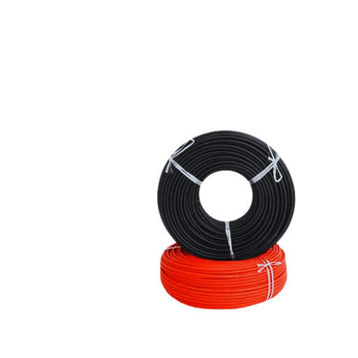
Q: What is the maximum length a solar panel extension cable is able to have?
A: The maximum length a solar panel extension cable can have is 50 feet. To cover the needs of different installations, solar panel extension cables often have lengths of 5ft, 10ft, 20ft, and also 50ft. The longest length a solar panel extension cable is able to have is determined by the wire’s gauge, as well as the electrical current passing through it. To improve the efficiency of your solar power system, it’s vital to choose the correct length and gauge.
Q: What are the differences between the H1Z2Z2-K cable and PV wire?
A: Designed for use in photovoltaic systems, both H1Z2Z2-K and PV wires are solar cables. PV wire, used in North America, and H1Z2Z2-K, a European standard, are both UV resistant and, therefore, suitable for outdoor use. Differences between these two types of cables come down to particular certifications and testing standards. Always be certain your solar cable fulfills the required specifications for the region and type of installation being used.
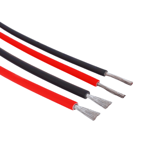
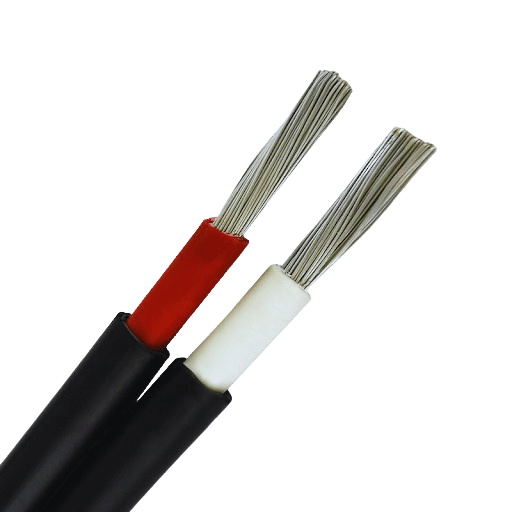
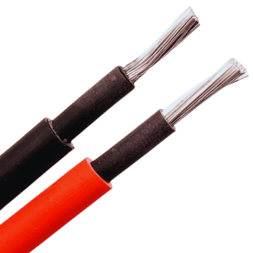
Q: Why are the colors of solar cables predominantly black and red?
A: The red cable is associated with the positive connection, while the black cable is associated with the negative connection. During installations or repairs, this color distinction reduces the chance of wiring mistakes. The red cable serves as the positive conductor, while the black cable serves as the negative conductor. It is easier to protect the solar power systems from incorrect polarity, which could harm the safe running of the system with the aid of these colors.
Q: For what reason is it important to use the right connectors in a solar-powered system?
A: The wrong connectors may lead to reduced safety and failure of the whole system. Ample security and weatherproofing of the solar components such as the solar panels, charge controllers, and the combiner boxes are achieved using the correct connectors. Failure of any type and arcing of the system could also be prevented. MC4 connectors tend to be the most common adapters which are used. Always ensure that the connectors used are not only for the components used but also the voltage and current for the whole system.
Q: How do I pick a solar cable kit for my off-the-grid solar system?
A: You want to think about the total wattage of your solar array, the distance between the panels and charge controller, the environmental conditions, and any other factors that can affect it. Ensure the solar cable kit has the right gauge wires like 10AWG or 14AWG, adequate connectors, and all the necessary adapters. These kits should also be labeled for outdoor use and preferably include some level of UV protection. If in doubt, it is smarter to go and speak with the cable maker or professional installer, as they will know which kit might work best for your requirements.
Q: How does a charge controller relate to solar cables in a PV system?
A: A charge controller is one of the core components of a PV system since it controls the solar voltage and current flowing from the panels to the battery bank. Solar cables carry electricity generated from the solar array to the charge controller. The charge controller receives this input and uses it to control the charging process of the batteries, avoiding overcharging and improving battery longevity. Correct sizing of solar cables ensures that the charge controller receives the best input from the solar panels, which improves overall system efficiency.
Reference Sources
1. Exposed Cables Ampacity Under Solar Radiation – The Standard’s Recommendations Versus CFD Simulation Results
- Author: S. Czapp et al.
- Year of Publication: 2018
- Discipline: Environmental Science
- Summary: This report analyzes the effects of ambient conditions on the ampacity of power cables placed in free air, focusing especially on the level of solar radiation. The authors perform comparisons of international standard-based ampacity calculations and CFD (Computational Fluid Dynamics) derived ones. The research demonstrates that the standards appear to include too many assumptions concerning the causes and effects relationship of the factors that impact ampacity and that CFD thermal representation of the conditions is more precise than the traditional standards.
- Key Findings: As Czapp et al. remarked in 2018, ‘the results demonstrate significant discrepancies of models, which directs to a strict need for proper standards-realistic modeling.’ For instance, they emphasize the lack of required standard-compliant modeling realism. Such results are logically anticipated for complex systems interaction models(Czapp et al., 2018, p. 03004).
2. The Numerical Analysis of Solar Radiation Impact on Current-Carrying Volume for PVC Insulated Power Cables
- Author: S. Czapp et al.
- Publication Year: 2019
- Fields of Study: Materials Science
- Summary: This article is a portion of a broader study that analyzes the impact of solar radiation on the current carrying capacity of PVC-insulated power cables and how their thermal behavior differs under various solar exposure scenarios. The authors use numerical methods for their calculations. Based on their results, it was determined that there is a strong possibility of a reduction in the current carrying capacity of the power cables, which poses a risk when dealing with solar energy applications.
- Key Findings: The research attempts to provide an understanding of the optimization issues from the circuitry side of the solar power systems, which the authors argue is frequently overlooked (Czapp et al., 2019).
3. Risk of Power Cables Insulation Failure Due to the Thermal Effect of Solar Radiation
- Authors: S. Czapp et al.
- Publication Year: 2020
- Fields of Study: Materials Science
- Summary: The paper deals with the problem of power cables’ insulation failure due to overheating from solar radiation. Insulation failure of either thermal or solar radiation interface cables can be caused by direct sunlight heating the cables. The research article pointed out the need to pay special attention to thermal conditions in the design and installation of power cables, particularly for solar energy systems.
- Key Findings: The results underscore the necessity to develop better insulation materials and their application processes in order to reduce the dangers of thermal failure of power cables (Czapp et al., 2020, pp. 232-240).
4. Enhancement of Ampacity for Underground Power Cables by Employing Photovoltaic Pavements
- Authors: D. Klimenta et al.
- Publication Year: 2018
- Fields of Study: Environmental Science
- Summary: The research investigates the use of photovoltaic pavements as a means to enhance the ampacity of underground power cables. The authors provide a case study that illustrates the benefits of using photovoltaic integrated cable installations to expose cables for better thermal management, as well as improve the current-carrying capacity of the cables.
- Key Findings: The study concludes that photovoltaic pavements combined with proper ventilation can greatly improve the working conditions of underground power cables, which makes them more useful in harnessing power from the sun (Klimenta et al., 2018, pp. 105-114).
5. CFD-based Evaluation of Current-Carrying Capacity of Power Cables Installed in Free Air
- Authors: S. Czapp et al.
- Publication Year: 2017
- Fields of Study: Engineering
- Summary: This paper studies the ampacity of power cables installed in the open air using CFD, taking into account solar radiation, wind, and other temperature effects of the surrounding environment. The authors prove that traditional practices are more likely to ignore these factors, resulting in cable underperformance.
- Key Findings: These results suggest that CFD simulations can give a more realistic evaluation of how cables function in the practical scenario which is crucial for the formulation of solar power systems (Czapp et al., 2017, pp. 1-6).
6. Wire
8. Solar power