






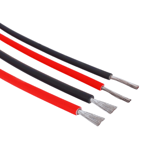
Die Nutzung von Solarenergiesystemen zur Energiegewinnung aus der Sonne ist einer der größten Schritte zur Erreichung nachhaltiger und erneuerbarer Energielösungen. Diese Systeme nutzen wichtige Teile, die eine reibungslose und zuverlässige Energieübertragung gewährleisten. Aus diesen Teilen heraus, Solarkabel und Steckverbinder dienen als Rückgrat für die sichere und effektive Übertragung von Strom aus Solarpaneelen Dieser Artikel konzentriert sich auf die grundlegende Wertschätzung dieser Komponenten, indem sie ihre Arten, Funktionalität und Umfang klären, um eine optimierte Gesamtsystemleistung zu erreichen Ob Sie ein Branchenprofi oder nur ein Hausbesitzer sind, der die Aussichten der Solarenergie abwägt, Kenntnisse über Solarkabel und Steckverbinder sind bei Design- und Wartungsentscheidungen für eine zuverlässige Solarstromanlage unverzichtbar.
Welche verschiedenen Arten von Solarkabeln werden in Solarstromanlagen verwendet?
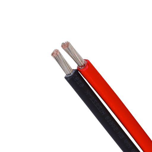
Normalerweise werden drei Kabelkategorien verwendet Solarstrom Systeme:
- PV-Kabel (Photovoltaik): Diese Kabel werden für die Verbindung von Solarpaneelen mit Wechselrichtern verwendet Diese Kabel sind mit starkem Kunststoff überzogen, der vor ultravioletten Strahlen schützt Diese Kabel sind außerdem wasserdicht und können hohe Temperaturen bewältigen.
- DC-Kabel (Gleichstrom): Diese Kabel transportieren den Strom vom Solarpanel zum Wechselrichter Diese Kabel sind auf Hochspannungsleistung gebaut und haben einen geringen Energieverlust.
- Wechselstromkabel (Wechselstrom): Diese Kabel verbinden den Ausgang des Wechselrichters mit dem Stromnetz oder der elektrischen Verkabelung des Gebäudes. Diese Kabel verfügen über eine Isolierung, die für zusätzliche Schutzabdeckung sorgt und die Effizienz verbessert.
Um die volle Funktionalität bei optimaler Spannung zu erreichen, ist der Einsatz spezieller Solarkabel ein Muss. Ohne sie werden elektrische Fehler und Verluste weit verbreitet sein.
Wie unterscheiden sich Solarkabel von herkömmlichem Draht?
Der Unterschied besteht darin, dass Solarkabel im Gegensatz zu den anderen Arten von Drähten für Solarstromanlagen konzipiert sind und funktionieren. Im Gegensatz zu den anderen Standarddrähten haben Solarkabel die Fähigkeit, ständiger Einwirkung von ultravioletten Strahlen, extremen Wetterbedingungen und rauen Umgebungsänderungen standzuhalten. Sie verfügen über eine doppelte Isolationsschicht, die dazu beiträgt, die Haltbarkeit, Sicherheit und Nutzung zu verbessern und gleichzeitig vor Kurzschlüssen oder Verschleiß im Laufe der Zeit zu schützen. Darüber hinaus verfügen Solarkabel über eine höhere Spannungs- und Stromkapazität, was zu einer effektiven Stromübertragung innerhalb der EU beiträgt Solaranlage. Im Gegensatz zu herkömmlichen Drähten weisen Solarkabel diese Eigenschaften auf, die sie härter und für die besonderen Anforderungen von Solarenergieanwendungen geeignet machen.
Welche Rolle spielen PV-Kabel in einer Photovoltaikanlage?
PV-Kabel, am besten bekannt als Photovoltaik-Kabel, sind so konzipiert, dass sie sich um spezifische und systemnahe Angelegenheiten in einer Solarenergieanlage kümmern Als solche sind sie in erster Linie ein Mittel, um Strom in Form von Gleichstrom (DC) aus dem Sonnenkollektoren zum Wechselrichter Zur Umwandlung in Wechselstrom (AC) Strom (wird in Haushalten, Industrie und Unternehmen verwendet) Zu den wichtigsten Eigenschaften von PV-Kabeln gehören eine hohe Hitzebeständigkeit (normalerweise bis zu 90°C oder mehr), UV-Strahlung und andere wetterfeste Eigenschaften, die eine bessere Lebensdauer im Laufe der Zeit unter allen äußeren Klimabedingungen gewährleisten.
Eines der Hauptelemente von PV-Kabeln ist die Fähigkeit, beispiellose Spannungsniveaus aufrechtzuerhalten und in modernen Solarsystemen 1.500 V Gleichstrom zu erreichen, was viel höher ist als bei Standard-Elektrokabeln. Diese Eigenschaft hat einen großen Einfluss auf die Effizienz und Skalierbarkeit von Solaranlagen, da sie sich direkt auf die von der Sonne empfangene Strommenge auswirken Außerdem bestehen PV-Kabel aus flammhemmenden und halogenfreien Materialien, was sie im Brandfall sicherer macht und internationalen Sicherheitsstandards wie IEC 62930 entspricht.
Durch die optimale Auswahl und Installation von Photovoltaikkabeln (PV) werden Energieverluste und Systemstillstände reduziert. Beispielsweise übertragen zuverlässige PV-Kabel Energie mit Verlusten unter 21 TP3 T, was zur Maximierung der Energieabgabe der Photovoltaikanlage beiträgt. Ihre langlebige Konstruktion ermöglicht ihnen ein Überleben von mehr als 25 Jahren, was häufig der Betriebsdauer von Solarmodulen entspricht. Dadurch werden die Austausch- und Wartungsanforderungen reduziert.
PV-Kabel müssen außerdem so konzipiert und eingesetzt werden, dass sie die anderen Komponenten von Solarsystemen unterstützen. Diese Kabel gewährleisten eine hohe Übertragungseffizienz sowie Systemzuverlässigkeit und -sicherheit und tragen daher zur Verbreitung erneuerbarer Energietechnologien bei.
Warum wird Kupferkonserven in Solarkabeln bevorzugt?
In Bezug auf Solarkabel wird Kupfer verzinnt aufgrund seiner elektromagnetischen Abschirmung und Korrosionsbeständigkeit bevorzugt Ohne die schützende Oxidschicht kann elektrisches blankes Kupfer korrodieren und oxidieren, wenn es Feuchtigkeit, Luft und anderen Umgebungselementen ausgesetzt wird, was die Wirksamkeit des Kabels minimiert und seine Lebensdauer verringert. Verzinntes Kupfer hält viel länger, da die innere Zinnschicht auch in Außenumgebungen eine gleichbleibende Leitfähigkeit und Haltbarkeit beibehält Aufgrund der extremen Wetter- und Sonnenbedingungen, denen Solarkabel ausgesetzt sind, ist Kupferverzinnt die beste Wahl für Solarkabel.
Wie wähle ich den richtigen Anschluss für Ihr Solarpanel aus?
Was ist bei der Auswahl eines Solaranschlusses zu beachten?
Die Wahl des richtigen Solaranschlusses ist unerlässlich, um Funktion, Effizienz, Langlebigkeit und Sicherheit in Ihrem Stromversorgungssystem zu maximieren. Bedenken Sie die folgenden Kernpunkte:
Betrachten Sie die Kompatibilität mit Solarpaneele und Kabel
- Überprüfen Sie, ob der Stecker mit Ihrem kompatibel ist Solarpaneele und Kabel Damit eine nahtlose Integration erreicht werden kann Die meisten Solarpaneele verfügen über MC4-Anschlüsse, die weit verbreitet sind, weil sie benutzerfreundlich und einfach zu verbinden sind. Überprüfen Sie außerdem die Drahtstärke und stellen Sie sicher, dass die Größe des Steckers für Ihre Kabel ausreicht, die bei Solaranwendungen typischerweise zwischen 14 AWG und 10 AWG variieren.
Untersuchen Sie die Strom- und Spannungsbewertungen
- Überprüfen Sie, ob der Stecker mit den Solarpaneelen und Kabeln kompatibel ist, damit eine Integration erreicht werden kann. Die meisten Solarpaneele verwenden MC4-Steckverbinder, die weit verbreitet sind, weil sie benutzerfreundlich und einfach zu verbinden sind. Überprüfen Sie außerdem die Drahtstärke und stellen Sie sicher, dass die Steckergröße für Ihre Kabel geeignet ist, die bei Solaranwendungen zwischen 14 AWG und 10 AWG liegen.
Wetterbedingungen und Langlebigkeit
- Die Solaranschlüsse für den Außenbereich müssen so ausgelegt sein, dass sie Unwettern wie ultravioletten Strahlen, Regenfällen und extremen Temperaturen standhalten. Suchen Sie nach Anschlüssen mit einer IP67-Einstufung oder vergleichbaren Einstufungen, die Schutz vor Staub und Wasser garantieren. Selbst in rauen Umgebungen verbessert die Verwendung von Isoliermaterialien wie Thermoplasten die Haltbarkeit des Steckverbinders.
Komfort bei Konfiguration und Wartung
- Das Design des Produkts fördert die Benutzerfreundlichkeit bei der Konfiguration und Wartung. Zahlreiche Solaranschlüsse verfügen über eine einfache Verriegelungsfunktion, die sowohl Sicherheit als auch einfache Trennung bei Systemänderungen oder Inspektionen gewährleistet. Darüber hinaus sind einige Werkzeuge wie Crimper oder spezielle Schraubenschlüssel erforderlich, sodass diese während der Konfiguration vor Ort vorhanden sein müssen.
Rechtmäßigkeit und Compliance
- Überprüfen Sie, ob die Solarsteckverbinder die Mindestanforderungen an Sicherheit und Leistung erfüllen, wie UL 6703, IEC 62852 oder TÜV-Zertifizierung Ein zertifiziertes Bauteil hat garantiert die notwendige Prüfung für Zuverlässigkeit und Sicherheit unter verschiedenen Betriebsumgebungen erfüllt, damit Sie keine minderwertigen Teile verwenden.
Performance-Versus-Kostenanalyse
- Ausgaben werden immer Entscheidungen beeinflussen, aber der Versuch, einen möglichst niedrigen Preis zu erzielen, kann Qualität und Effizienz beeinträchtigen Steckverbinder, die teurer in der Anschaffung sind, können ihre günstigeren Äquivalente übertreffen und höhere Einsparungen bei den Wartungskosten bieten Zuverlässigkeit erreichen und gleichzeitig die Kosteneffizienz mit der richtigen Strategie optimieren.
Ihr Solarstromanlage Sicherheit und Leistung können mit Qualitätsanschlüssen gewährleistet werden, wenn diese Faktoren bewertet werden Richtig ausgewählte Anschlüsse bieten weitere Vorteile wie geringere Energieverluste, verbesserte Leistung und erhöhte Haltbarkeit der gesamten Anlage.
Wie steigert MC4-Stecker die Effizienz?
Durch die Eliminierung unnötiger Energieverluste und die Herstellung einer sicheren Verbindung zwischen Solarpaneelen und anderen Systemkomponenten verbessern MC4-Steckverbinder die Gesamteffizienz des Solarenergiesystems. Ihr Design ermöglicht eine eng anliegende, wasserdichte Abdichtung, die Feuchtigkeit und Staub als Umweltfaktoren schützt, die die Leistung beeinträchtigen können Darüber hinaus ermöglichen MC4-Steckverbinder eine schnelle und reibungslose Plug-and-Play-Installation, was eine geringere Wahrscheinlichkeit von Fehlern ermöglicht, die die Effizienz beeinträchtigen können. All diese Funktionen führen zu einer größeren Zuverlässigkeit des Systems als Ganzes und einer optimierten Energieerzeugung.
Wie kann die ordnungsgemäße Installation von Steckverbindern sichergestellt werden?
In der Regel muss jede Komponente in einem Solarstromanlage das gleiche Design und die gleiche Spezifikation verwenden, um ordnungsgemäß zu funktionieren. Nachfolgend finden Sie Verfahren, die den ordnungsgemäßen Einbau von Steckverbindern leiten:
Verwenden Sie geeignete Teile
- Mit anderen Worten, bestätigen Sie, dass die verwendeten Steckverbinder von der richtigen Art, Größe und Bewertung sind, wobei das Kabel verwendet wird. MC4-Steckverbinder funktionieren beispielsweise am besten mit 4 mm quadratischen bis 6 mm großen Quadratkabeln. Komponenten, die nicht richtig ausgerichtet sind, können eine Quelle für Stromverluste sein oder sogar die Sicherheit beeinträchtigen.
Bereiten Sie Kabel richtig vor
- Kabelisolierung, die entfernt werden muss, kommt mit einer festgelegten Länge (im Allgemeinen zwischen 6 bis 7 mm), und es ist am besten, sicherzustellen, dass die Stränge des Leiters nicht gebrochen sind. Gebrochene Stränge können die Konnektivität erschweren und die Möglichkeit einer zu starken Temperaturerhöhung erhöhen.
Steckverbinder Crimpen
- Verwenden Sie ein einzigartiges Crimpwerkzeug, das zertifiziert ist, um den Steckerstift fest am Kabel zu befestigen Verwenden Sie keine unspezifischen Werkzeuge, da viele von ihnen nicht in der Lage sind, die richtige Kraft zu liefern, was die Verbindungen festzieht und zu losen Verbindungsstellen oder Lichtbögen führt.
Polarität gewährleisten
- Bestätigen Sie die Polarität der Steckverbinder und Kabel zum zweiten Mal. Wenn Sie negativ platzieren, wo positiv zu erwarten ist, und umgekehrt, kommt es zu Systemfehlern oder ausfahrbaren Armen.
Letzte Anziehungsschritte
- Polaritätskontrollen sind der letzte Schritt vor dem Einsetzen der Kabel und stellen sicher, dass die Kabel jederzeit so funktionieren, wie sie sollen. Ihre Sicherheit wird also durch diese Mechanismen untermauert, die eine nachhaltige Effizienz des Stromnetzes gewährleisten.
Wenden Sie das richtige Drehmoment an: Untersuchen Sie die Anweisungen
- Um sicherzustellen, dass Kappen oder Verriegelungsmechanismen bei Verwendung von MC4-Steckern wasser- und staubdicht sind, ist ein Anzugsdrehmoment von 2,5-3,0 Nm beim Anziehen der Steckverbinder vorgesehen.
- Ziehen Sie mit einem Kappenschlüssel die Kappe oder den Verriegelungsmechanismus mit dem angegebenen Anzugsmoment von normalerweise 2,5 µm fest.
Überprüfen Sie auf Mängel
- Bewerten Sie die Verbindungskomponenten auf äußere Anzeichen von Verformung wie Risse, Brüche oder Fehlausrichtung nach der Montage. Die Verwendung dieser Anschlüsse sollte nicht zulässig sein, da sie als fehlerhaft gelten, da sie die Systemintegrität beeinträchtigen.
Führen Sie ein Testverfahren für die elektrische Kontinuität durch
- Prüfen Sie mit einem Multimeter die elektrische Verbindungskontinuität und prüfen Sie auch in den Gelenken auf minimalen Widerstand Erhöhte Widerstandswerte können auf eine unvollständige oder beschädigte Verbindung hinweisen.
Umweltaspekte
- Überprüfen Sie, ob der gesamte Bereich um die Anlage herum ordentlich und nicht nass ist Vermeiden Sie staubige oder nasse Installationen, da diese und andere Verunreinigungen nicht bei ihrer Leistung oder Abdichtung helfen.
Befolgen Sie die Herstellerrichtlinien
- Halten Sie sich an die für den Steckerhersteller spezifischen Anweisungen Die meisten dieser Richtlinien enthalten neben der ordnungsgemäßen Verwendung sinnvolle Empfehlungen und Anforderungen zur Installation und Wartung.
Unter Berücksichtigung all dieser Anweisungen wird eine ordnungsgemäße Anpassung erreicht, sodass die Anschlüsse optimal in einem Solarstromanlage platziert werden, wodurch Leistungsprobleme minimiert und die Langlebigkeit der Komponenten im System erhöht werden.
Wie installiere ich Solarpanelkabel sicher?
Was sind UL-Standards für elektrische Sicherheit?
UL-Standards für elektrische Sicherheit sind festgelegte Richtlinien von Underwriters Laboratories, die auf die sichere Konstruktion, Installation und Funktion elektrischer Systeme und Komponenten abzielen. Die Standards konzentrieren sich in erster Linie auf die Verringerung der Risiken im Zusammenhang mit Stromschlägen, Bränden und sogar mechanischen Gefahren. Sie legen einen niedrigeren Maßstab für die Zuverlässigkeit der Ausrüstung und die Einhaltung vor Ort fest, indem sie systematische Tests und Zertifizierungskriterien bereitstellen, die eindeutig bestätigen, dass die Ausrüstung strenge Sicherheitsvoraussetzungen erfüllt. Die Einhaltung der Ul-Standards stellt sicher, dass die Sicherheits- und entsprechenden regulatorischen Anforderungen für Solarpanelsysteme Erfüllt sind.
Wie kann man Solarkabel richtig isolieren?
Die ordnungsgemäße Installation von Solarkabeln ist entscheidend für die Effizienz und Sicherheit eines Solarstromanlage Wie die meisten Kabel sind auch Solarkabel harten Umweltfaktoren wie UV-Strahlen, Feuchtigkeit, Temperatur und mechanischer Belastung ausgesetzt. Daher helfen die folgenden Schritte dabei, das geeignete Verfahren zur Isolierung von Solarkabeln zu steuern:
Wählen Sie den richtigen Kabeltyp aus
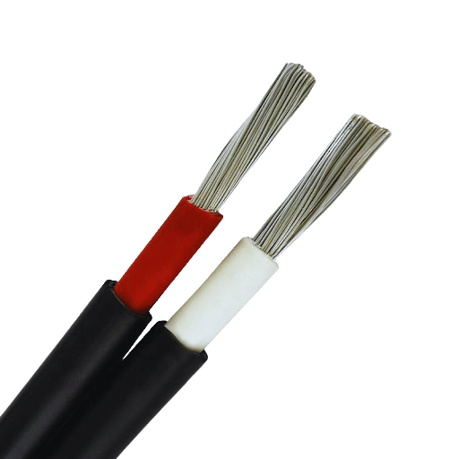
- PV (Photovoltaik) - Anlagenkomponenten haben strenge Isoliermaterialanforderungen TÜV - und UL-konforme Solarkabel haben doppelte Isolierschichten, die aus vernetztem Polyethylen (XLPE) oder Gummimischungen bestehen, die hoch beständig gegen UV-Strahlung und hohe Temperaturen sind, so können beispielsweise XLPE-isolierte Solarkabel, die recht häufig sind, von -40 C bis 90 Grad Celsius betrieben werden.
Installieren Sie wetterfeste Anschlusskästen
- Ebenso sollten Anschlussdosen nicht über der Wetterschutzbewertung liegen, sie sollten auch mit entsprechenden IP-Bewertungen (Eingangsschutz) konform sein, zum Beispiel IP65 oder höher. Dies ist wichtig, da das Eindringen von Feuchtigkeit zu Problemen bei der Isolierung und Isolierung führen kann Elektrische Leitungen Leistung.
Verwenden Sie UV-stabile Kabelbinder und -leitungen
- Solarkabel sollten gesichert werden, um zu vermeiden, dass sich Solarkabel mit dem Wind bewegen. Schutzleitungen können nach Möglichkeit auch neben UV-stabilen Kabelbindern verwendet werden. Leitungen sorgen außerdem für eine gewisse Zugentlastung, während UV-stabile Materialien jegliche Verschlechterung durch Sonneneinstrahlung verhindern.
Übermäßige Kabellängen verhindern
- Um unnötigen Durchhang zu reduzieren, der zu Biegung und eventuellem Verschleiß führen kann, sollte die Kabelspannung minimiert werden. Richtlinien empfehlen, Kabel auf knapp über die erforderliche Länge zu schneiden, die die gewünschten Verbindungspunkte erreichen kann.
Stellen Sie routinemäßige Wartung und Kontrollen sicher
- Umweltfaktoren können die Isolierung verschleißen und Ecken und Kanten erhalten Solarkabel sollten routinemäßig auf sichtbare Risse, Verfärbungen oder allgemeinen Verschleiß beim Entleeren untersucht werden Widerstandsprüfer können die Gesundheit der Isolierung des Solarkabels überprüfen, und die Abdeckung des Solarkabels kann zur Zustandsbewertung entfernt werden.
Halten Sie sich an die Strom- und Spannungsbewertung
- Die eingestellten Grenzwerte von Spannung oder Strom müssen den Isolationseigenschaften des Bauteils angemessen entsprechen, so hat beispielsweise die Isolierung der am häufigsten verwendeten Solar-Gleichstromkabel einen Grenzwert von 1.000 V bis 1.500 V. Die Verwendung von unterbewerteten Kabeln kann zu Isolationsausfällen und Sicherheitsrisiken führen.
Zusammengenommen stellen diese Praktiken sicher, dass die Isolierung von Solarkabeln zuverlässig bleiben und den festgelegten Industriestandards standhalten kann, um eine optimale Leistung des Systems zu gewährleisten und für den langfristigen Einsatz sicher zu sein.
Best Practices zur Reduzierung des Spannungsverlusts in Kabeln
Um den Spannungsabfall in Elektro - und Solaranlagen zu verringern, sollten stets die folgenden bewährten Verfahren befolgt werden Die Umsetzung dieser Verfahren führt zu einer effektiveren Energieübertragung, einem besseren Systembetrieb und weniger Abfall:
Korrekte Kabelauswahl
- Der Querschnitt eines Kabels definiert seine Fläche, und das bestimmt auch den Spannungsabfall. Wenn die Fläche größer ist, ist der Widerstand kleiner, was bedeutet, dass die Verwendung größerer Kabel zu einem geringeren Spannungsabfall führt. Wenn Sie beispielsweise in einer Solaranlage ein 6 mm² großes Kabel anstelle eines 4 mm² großen Kabels für einen 30-Meter-Lauf verwenden, bedeutet dies etwa 331 TP3 T weniger Spannungsverlust. Überprüfen Sie immer relevante Standards für das richtige Kabel hinsichtlich Strom-, Entfernungs- und akzeptablen Verlustzahlen.
Reduzierung der Kabellänge
- Geringerer Widerstand bedeutet kürzere Spannung Tropfen und kürzeres Kabel Läufe Wenn es möglich ist, erstellen Sie ein Design für das System, das die Komponenten des Systems wie Solarpaneele, Wechselrichter und Batterien zusammenhält. Wenn Sie beispielsweise die Länge des Kabels halbieren, wird auch der Spannungsverlust um die Hälfte reduziert.
Hochwertige Leiter
- Niedriger Widerstand bedeutet, dass Leitungsmaterialien in Premiumqualität wie Kupfer oder Aluminium die besten da draußen sind Kupfer gilt aufgrund seines Widerstands von 1,68 µ µm als die beste Wahl, dass die Verwendung von Aluminium bedeutet, dass der Leiter vergrößert werden muss, um die gleiche Leistung wie bei Kupfer erbringen zu können.
Verbindungen sicher machen
- Die Erwärmung der Verbindungen und ein größerer Spannungsverlust aufgrund schlechter oder lockerer Bewegungen führen zu mehr Widerstand als akzeptabel. Verwenden Sie daher geeignete Anschlüsse und überprüfen Sie die Verbindungen auf Sicherheit und Korrosion im Laufe der Zeit. Sie sollten sich über die Dauer der Zeit nicht ändern.
Arbeiten Sie mit den Nennströmen von Cables
- Zulassen, dass Kabel über ihren Nennstrom gehen, führt zu einer Überhitzung, die zu einem Verlust des Widerstands führt und den Verlust der Spannung erhöht. Durch die Einhaltung der Herstellerangaben bezüglich der Nennstromstärke werden Schäden am Kabel und unnötige Energieverluste vermieden.
Verwendung von Strangdrähten anstelle von Einzeldraht
- Mehrsträngige Leiter sind dünner und haben im Vergleich zu einzelsträngigen Leitern eine größere Fläche. Dies kann den Widerstand auf ein geringes Maß verringern, insbesondere bei Anwendungen mit hohen Frequenzen, die aufgrund des Skineffekts mehr Effizienz vom System erfordern.
Anpassungen mithilfe der Berechnung des Spannungsabfalls vornehmen
- Führen Sie Spannungsabfallberechnungen während der Entwurfsphasen in jedem Fall durch, um zu garantieren, dass alles optimal funktioniert Überall von fünf bis drei Prozent der Systemspannung ist mit ein paar Installationen akzeptabel In einem System mit einem 12 V muss der gesamte Spannungsabfall 0,36 bis 0,6 V betragen.
Regelmäßige Überprüfung und Wartung des Systems
- Aufgrund der Reduzierung der Widerstandsverluste und der Steigerung der Wirksamkeit des Systems sollten Schritte unternommen werden, um diese Systeme aufrechtzuerhalten und die Vorteile zu nutzen.
Durch die Integration dieser Ansätze wird die Ineffizienz von Elektro- und Solarkabelsystemen verringert und die Nachhaltigkeit der Energie und die Betriebssicherheit im Prozess verbessert.
Was sind die wichtigsten Überlegungen für Solarverlängerungskabel?
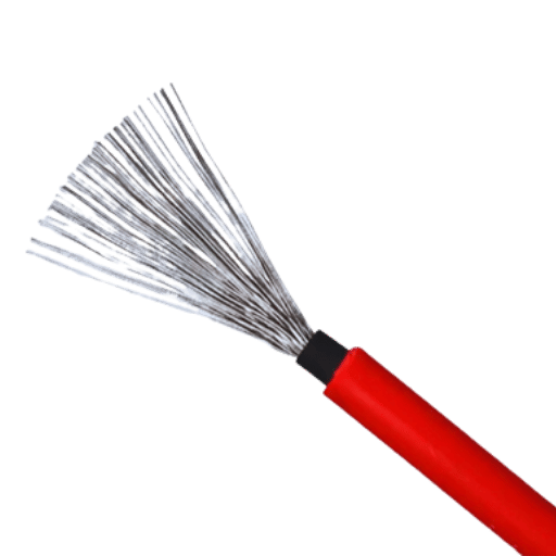
Welchen Einfluss hat die Kabellänge auf die Systemleistung?
Die Kabellänge hat einen direkten Einfluss auf die Leistung des Systems, vor allem wegen der Wechselwirkungen des Widerstands innerhalb des Systems Lange Kabel haben einen vergleichsweise grenzüberschreitenden Widerstandsverlust, der zu einer ineffizienten Kraftübertragung und Produktivitätseinbrüchen führen kann Um solche Verluste auszugleichen, ist es notwendig, Kabel mit den richtigen Abmessungen und dem richtigen Durchmesser des Leiters sowohl für den Strom als auch für die Strecke zu verwenden Kürzere Kabelwege sind normalerweise besser, da sie dazu beitragen, den Verlust von Leistung und Schwankungen der Spannung zu reduzieren, damit das System gut funktioniert.
Wie wählt man zwischen 50 Fuß und anderen Verlängerungskabeloptionen?
Einige entscheidende Faktoren wie Strombedarf, Spannungsabfall und beabsichtigte Anwendung müssen bei der Wahl zwischen einem 50-Fuß-Verlängerungskabel und anderen Optionen berücksichtigt werden. Das wichtigste technische Problem bei längeren Kabeln betrifft den Spannungsabfall, bei dem es sich um die Schwäche der Spannung handelt innerhalb eines Kabels aufgrund des Widerstands. Auf der Grundlage elektrischer Normen wird davon ausgegangen, dass der Spannungsabfall mit jedem Fuß zusätzlicher Kabellänge direkt proportional zunimmt, was Risiken für empfindliche Geräte oder Hochleistungsanwendungen mit sich bringt.
Zur Veranschaulichung wird ein 15-Ampere-Verlängerungskabel bei 120 Volt, abhängig von der Drahtlehre, einen Spannungsabfall von zwei bis drei Prozent über einen Lauf von 50 Fuß erleiden Bei diesen Dickenmessdrähten besteht die Gefahr, dass die Leistung erreicht wird. Bei kürzeren Läufen hingegen tun dünnere Drähte, weil die Widerstandsverluste geringer sind.
Abgesehen davon stellt die Kabellänge Sicherheitsherausforderungen dar Lange Verlängerungskabel neigen dazu, überlastet zu sein, was zu Erwärmung und Schäden an den Geräten oder zur Laufzeit führen kann. Der National Electrical Code (NEC) enthält Standards, die empfehlen, den Strombedarf mit der kürzesten Länge zu decken, was auch sicherstellt, dass die Systeme unter optimalen Bedingungen arbeiten.
Wenn Mobilität eine Notwendigkeit ist, sollten Sie möglicherweise die Verwendung einziehbarer Verlängerungskabel in Betracht ziehen, die an Ihre spezifischen Bedürfnisse angepasst werden können. Die Bewertung der Leistung, die Ihre Geräte verbrauchen, sowie das Design Ihres Setups helfen Ihnen bei der Entscheidung, ob ein 50-Fuß-Kabel oder andere Optionen das perfekte Gleichgewicht der Wirksamkeit bieten, sowohl im Hinblick auf Sicherheit als auch auf Finanzen.
Warum wird 10 AWG häufig in Solarsystemen verwendet?
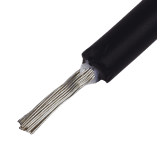
Verständnis der Spannungs- und Strombewertung von 10 AWG
Mir ist klar, dass die Wahl von 10 AWG für eine Solaranlage einen optimalen Kompromiss hinsichtlich Stromkapazität und Spannungsabfall darstellt. Wenn man bedenkt, dass es bis zu 30 Ampere transportieren kann, ohne einen nennenswerten Widerstand pro Längeneinheit zu erleiden, funktioniert 10 AWG über längere Distanzen gut, um Energieverluste zu minimieren und so eine höhere Gesamtsystemeffizienz zu ermöglichen. Es entspricht gut den durchschnittlichen Leistungs- und Stromanforderungen der meisten Haushaltssolarsysteme und bietet somit eine hervorragende Energieübertragung ohne Risiko oder Ausfall.
Vergleich von 10 AWG mit anderen Messgeräten in Solarenergieanwendungen
Bei Solaranwendungen muss die Auswahl der Drahtstärke ihre Strombelastbarkeit, Entfernung und Effizienz berücksichtigen. Dickere Drähte wie 10 AWG leiten höhere Ströme mit geringerem Widerstand als dünnere Drähte wie 12 AWG; Dies ist besonders vorteilhaft für die Energieübertragung über große Entfernungen. Drähte mit 8 AWG haben eine noch größere Stromkapazität, aber ihre Kosten und die geringere Flexibilität machen sie für die meisten Wohnsysteme weniger geeignet. 10 AWG eignet sich am besten für die meisten Solaranlagen für Privathaushalte, da es relativ kostengünstig und einfach zu installieren ist und dennoch eine gute Energieübertragung ermöglicht.
Wie warte ich Ihre Solarstromkabel für Langlebigkeit?
Wie wirkt sich Sonnenlicht auf Solarkabel aus?
Solarkabel sind so gebaut, dass sie unter rauen Bedingungen aufgrund längerer Sonneneinstrahlung halten können UV-Strahlung kann jedoch die Isolierschicht allmählich abbauen, wodurch sie spröde, rissig oder im Laufe der Zeit ineffizient wird Außerdem können interne Schaumkernmaterialien ihre Polymermatrix verlieren, was zu einer erhöhten Sprödigkeit führt Diese Kaskadeneffekte können das empfindliche Gleichgewicht von Effizienz und Sicherheit innerhalb des Systems beschädigen.
Die Lebensdauer von Solarkabeln korreliert stark mit der Art und Qualität der verwendeten Materialien UV-beständige stabilisierte Materialien, insbesondere vernetztes Polyethylen (XLPE), widerstehen nachweislich dem Verfall und halten eine effektive Leistung über Jahrzehnte aufrecht, so können XLPE-Kabel beispielsweise bei direkter Sonneneinstrahlung eine Lebensdauer von 25 Jahren überschreiten, was sie zur bevorzugten Wahl in modernen Solaranlagen macht.
Ein weiterer Aspekt, der durch Sonneneinstrahlung verändert werden kann, ist seine Temperatur Solarbetriebene Kabel, die direkter Sonneneinstrahlung ausgesetzt sind, können aufgrund der Erwärmung einen Anstieg der Arbeitstemperatur haben, und das beeinflusst ihre Tragfähigkeit. Im Allgemeinen stellen Hersteller einen Deratationsfaktor bereit, um diesem Effekt entgegenzuwirken, damit die Ingenieure sich während der Systemkonstruktionsphasen um temperaturbasierte Leistungsschwankungen kümmern können. Eine ordnungsgemäße Verwaltung der Kabelführung unter Verwendung reflektierender und nichtleitender Leitungen, damit Sonnenlicht nicht direkt auf das Kabel einwirkt, kann bei der Lösung einiger dieser Probleme helfen, was zu einer besseren Leistung und einer längeren Betriebslebensdauer beiträgt.
Kabel, die eine TÜV- oder UL-PV-Zertifizierung tragen, sind international anerkannt und versichern, dass sie Umweltschäden wie UV-Strahlung standhalten. Ein solcher Schutz ist für die Effizienz und Sicherheit von Solarstromanlagen über einen langen Zeitraum wichtig.
Welche Wartung ist für netzunabhängige und netzunabhängige Systeme erforderlich?
Off-Grid-Systeme erfordern eine routinemäßige Diagnose des Batteriezustands, da es sich hierbei um kritische Komponenten zur Energiespeicherung handelt. Dazu gehören die Überprüfung des Elektrolytgehalts (falls zutreffend), die Sicherstellung ordnungsgemäßer Ladestände und die Wartung der Anschlussverbindung, um Korrosion zu vermeiden. Gelegentlich können durch die Reinigung von Solarpaneelen Effizienzbarrieren wie Schmutz beseitigt werden. Es ist auch wichtig, die Anschlüsse, Wechselrichter und Drähte des Systems auf Anzeichen von Beschädigung oder Verschleiß zu überprüfen.
Netzsysteme erfordern normalerweise nicht so viel Wartung; eine gelegentliche Reinigung oder Inspektion durch Spezialisten wird den Panels jedoch helfen, optimal zu arbeiten Außerdem sollten der Wechselrichter und andere elektrische Systeme von Zeit zu Zeit visuell auf Fehler oder andere Probleme überprüft werden Das Energiemanagement wird vom Netz übernommen; daher kann die Leistungsüberwachung durch Systemsoftware dazu beitragen, Probleme zu identifizieren, die proaktiv angegangen werden müssen.
Häufig gestellte Fragen (FAQs)
F: Warum sind Kabel und Solaranschlüsse für ein Solarsystem wichtig
A: Das Solarkabel und die Anschlüsse spielen eine wichtige Rolle in einem Solarstromsystem. Sie ermöglichen es den Solarmodulen, Strom an den Laderegler und die Batteriebank zu liefern. Diese Komponenten sind speziell für den Widerstand gegen Außen- und Umgebungsbedingungen hergestellt, was einen weiteren Aussichtspunkt für die Schadensbegrenzung bietet und gleichzeitig die Effizienz des Stromflusses in Photovoltaik-Stromsystemen gewährleistet.
F: Wie lang kann ein Solarpanel-Verlängerungskabel maximal sein?
A: Die maximale Länge, die ein Solarpanel-Verlängerungskabel haben kann, beträgt 50 Fuß Um den Bedarf verschiedener Installationen zu decken, haben Solarpanel-Verlängerungskabel oft Längen von 5 ft, 10 ft, 20 ft, und auch 50 ft. Die längste Länge, die ein Solarpanel-Verlängerungskabel haben kann, wird durch die Spurweite des Drahtes bestimmt, sowie durch den elektrischen Strom, der durch ihn hindurchgeht. Um die zu verbessern Effizienz Ihrer Solarstromversorgung System, ist es wichtig, die richtige Länge und Spurweite zu wählen.
F: Was sind die Unterschiede zwischen dem H1Z2Z2-K-Kabel und dem PV-Kabel?
A: Ausgelegt für den Einsatz in Photovoltaikanlagen, sind sowohl H1Z2Z2-K - als auch PV-Drähte Solarkabel PV-Draht, verwendet in Nordamerika, und H1Z2Z2-K, eine europäische Norm, sind beide UV-beständig und daher für den Außenbereich geeignet Unterschiede zwischen diesen beiden Kabeltypen hängen von besonderen Zertifizierungen und Prüfstandards ab Seien Sie immer sicher, dass Ihr Solarkabel die erforderlichen Spezifikationen für die Region und die Art der verwendeten Installation erfüllt.
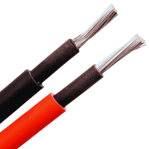
F: Warum sind die Farben von Solarkabeln überwiegend schwarz und rot?
A: Das rote Kabel ist mit dem positiven Anschluss verbunden, während das schwarze Kabel mit dem negativen Anschluss verbunden ist Bei Installationen oder Reparaturen verringert diese Farbunterscheidung die Wahrscheinlichkeit von Verkabelungsfehlern, das rote Kabel dient als positiver Leiter, während das schwarze Kabel als negativer Leiter dient, einfacher ist es, die Solarstromanlagen vor falscher Polarität zu schützen, was den sicheren Betrieb der Anlage mit Hilfe dieser Farben beeinträchtigen könnte.
F: Aus welchem Grund ist es wichtig, die richtigen Steckverbinder in einer solarbetriebenen Anlage zu verwenden?
A: Die falschen Anschlüsse können zu einer verminderten Sicherheit und einem Ausfall des gesamten Systems führen. Eine umfassende Sicherheit und Wetterfestigkeit der Solarkomponenten wie der Solarpaneele, Ladungsregler und der Kombiniererboxen wird durch die richtigen Anschlüsse erreicht. Auch ein Ausfall jeglicher Art und eine Lichtbogenbildung des Systems könnten verhindert werden. MC4-Anschlüsse sind in der Regel die am häufigsten verwendeten Adapter Stellen Sie immer sicher, dass die verwendeten Anschlüsse nicht nur für die verwendeten Komponenten, sondern auch für die Spannung und den Strom für das gesamte System bestimmt sind.
F: Wie wähle ich ein Solarkabel-Kit für meine netzunabhängige Solaranlage aus?
A: Sie möchten über die Gesamtleistung Ihrer Solaranlage, den Abstand zwischen den Paneelen und dem Laderegler, die Umgebungsbedingungen und alle anderen Faktoren, die sie beeinflussen können, nachdenken Stellen Sie sicher, dass das Solarkabel-Kit über die richtigen Messdrähte wie 10 AWG oder 14 AWG, angemessene Anschlüsse und alle notwendigen Adapter verfügt Diese Kits sollten auch für den Außenbereich gekennzeichnet sein und vorzugsweise ein gewisses Maß an UV-Schutz enthalten. Im Zweifelsfall ist es intelligenter, mit dem Kabelhersteller oder professionellen Installateur zu sprechen, da dieser weiß, welches Kit für Ihre Anforderungen am besten geeignet ist.
F: Wie verhält sich ein Laderegler zu Solarkabeln in einer PV-Anlage?
A: Ein Laderegler ist eine der Kernkomponenten einer PV-Anlage, da er die von den Paneelen zur Batteriebank fließende Solarspannung und den Strom steuert Solarkabel transportieren Strom, der von der Solaranlage zum Laderegler erzeugt wird Der Laderegler empfängt diesen Eingang und steuert damit den Ladevorgang der Batterien, wodurch Überladung vermieden und die Batterielebensdauer verbessert wird Durch die richtige Dimensionierung der Solarkabel wird sichergestellt, dass der Laderegler den besten Eingang von den Solarmodulen erhält, was die Gesamtsystemeffizienz verbessert.
Referenzquellen
1. Exponierte Kabel Undurchsichtigkeit Unter Sonnenstrahlung – Die Empfehlungen des Standards im Vergleich zu CFD-Simulationsergebnissen
- Autor: S. Czapp et al.
- Erscheinungsjahr: 2018
- Disziplin: Umweltwissenschaft
- Zusammenfassung: Dieser Bericht analysiert die Auswirkungen von Umgebungsbedingungen auf die Ampazität von in freier Luft platzierten Stromkabeln und konzentriert sich dabei insbesondere auf die Höhe der Sonneneinstrahlung. Die Autoren führen Vergleiche internationaler standardbasierter Ampazitätsberechnungen durch und leiten daraus CFD (Computational Fluid Dynamics) ab. Die Forschung zeigt, dass die Standards offenbar zu viele Annahmen über die Ursachen und Auswirkungen der Faktoren enthalten, die sich auf die Ampazität auswirken, und dass die thermische CFD-Darstellung der Bedingungen präziser ist als die herkömmlichen Standards.
- Wichtigste Ergebnisse: Wie Czapp et al. 2018 bemerkten, zeigen ‘die Ergebnisse erhebliche Diskrepanzen bei Modellen, was auf die strikte Notwendigkeit einer ordnungsgemäßen standardrealistischen Modellierung zurückzuführen ist.’Sie betonen beispielsweise das Fehlen eines erforderlichen standardkonformen Modellierungsrealismus. Solche Ergebnisse werden logischerweise für komplexe Systeminteraktionsmodelle erwartet(Czapp et al., 2018, S. 03004).
2. Die numerische Analyse der Auswirkungen der Sonnenstrahlung auf das stromdurchlässige Volumen für PVC-isoliert Stromkabel
- Autor: S. Czapp et al.
- Erscheinungsjahr: 2019
- Studienrichtungen: Materialwissenschaft
- Zusammenfassung: Dieser Artikel ist ein Teil einer umfassenderen Studie, die die Auswirkung der Sonnenstrahlung auf die Strombelastbarkeit von PVC-isolierten Stromkabeln analysiert und wie sich ihr thermisches Verhalten unter verschiedenen Szenarien der Sonnenexposition unterscheidet Die Autoren verwenden numerische Methoden für ihre Berechnungen, anhand ihrer Ergebnisse wurde festgestellt, dass eine starke Möglichkeit einer Verringerung der Strombelastbarkeit der Stromkabel besteht, was ein Risiko im Umgang mit Solarenergieanwendungen darstellt.
- Wichtigste Ergebnisse: Die Forschung versucht, ein Verständnis der Optimierungsprobleme auf der Schaltkreisseite der Solarenergiesysteme zu vermitteln, die nach Ansicht der Autoren häufig übersehen werden (Czapp et al., 2019).
3. Risiko eines Versagens der Stromkabelisolierung aufgrund der thermischen Wirkung der Sonnenstrahlung
- Autoren: S. Czapp et al.
- Erscheinungsjahr: 2020
- Studienrichtungen: Materialwissenschaft
- Zusammenfassung: Das Papier befasst sich mit dem Problem des Isolationsversagens von Stromkabeln aufgrund von Überhitzung durch Sonneneinstrahlung. Isolationsversagen von Wärmestrahlungs- oder Solarstrahlungsschnittstellenkabeln kann durch direkte Sonneneinstrahlung verursacht werden. Der Forschungsartikel wies darauf hin, dass bei der Konstruktion und Installation von Stromkabeln, insbesondere für Solarenergiesysteme, besonderes Augenmerk auf die thermischen Bedingungen gelegt werden muss.
- Wichtigste Ergebnisse: Die Ergebnisse unterstreichen die Notwendigkeit, bessere Isoliermaterialien und deren Anwendungsprozesse zu entwickeln, um die Gefahren eines thermischen Versagens von Stromkabeln zu verringern (Czapp et al., 2020, S. 232-240).
4. Verbesserung der Auslastung unterirdischer Stromkabel durch den Einsatz von Photovoltaik-Pflastersteinen
- Autoren: D. Klimenta et al.
- Erscheinungsjahr: 2018
- Studienrichtungen: Umweltwissenschaft
- Zusammenfassung: Die Forschung untersucht den Einsatz von Photovoltaik-Belägen als Mittel zur Verbesserung der Strombelastbarkeit von Erdstromkabeln. Die Autoren stellen eine Fallstudie bereit, die die Vorteile der Verwendung integrierter Photovoltaik-Kabelinstallationen zur Freilegung von Kabeln für ein besseres Wärmemanagement sowie zur Verbesserung der Strombelastbarkeit der Kabel veranschaulicht.
- Wichtigste Ergebnisse: Die Studie kommt zu dem Schluss, dass Photovoltaikbeläge in Kombination mit ordnungsgemäßer Belüftung die Arbeitsbedingungen von Erdstromkabeln erheblich verbessern können, was sie für die Nutzung der Sonnenenergie nützlicher macht (Klimenta et al., 2018, S. 105-114).
5. CFD-basierte Bewertung der Stromtragfähigkeit von in Freiluft installierten Stromkabeln
- Autoren: S. Czapp et al.
- Erscheinungsjahr: 2017
- Studienrichtungen: Ingenieurwesen
- Zusammenfassung: In diesem Artikel wird die Ampazität von im Freien installierten Stromkabeln mithilfe von CFD untersucht, wobei Sonneneinstrahlung, Wind und andere Temperatureffekte der Umgebung berücksichtigt werden. Die Autoren beweisen, dass traditionelle Praktiken diese Faktoren eher ignorieren, was zu einer Unterleistung des Kabels führt.
- Wichtigste Ergebnisse: Diese Ergebnisse legen nahe, dass CFD-Simulationen eine realistischere Bewertung der Funktionsweise von Kabeln im praktischen Szenario liefern können, das für die Formulierung von Solarstromanlagen von entscheidender Bedeutung ist (Czapp et al., 2017, S. 1-6).
6. Draht
8. Solarstrom