Every electrical project requires safety and efficiency, which is why knowing what wire gauge to use is crucial. The American Wire Gauge system, along with others, creates standards that help streamline systems by providing touch poles for DIY and professional projects. Given its prudent level of conductivity and durability, 12 gauge wire is one of the most used wires in the world and the focus of this article. This article intends to provide technical information like the characteristics and uses of 12 gauge wires, transforming measurements of AWG to usable engineering units, as well as offering versatile insights to help formulate educated decisions for systems improvement.
What is AWG, and How Does it relate to Wire Sizes?

American Wire Gauge (AWG) allows for the measurement and categorization of wires based on their diameter. The gauge size indicates how thick the wire is, where smaller gauges correlate to thicker wires, while larger gauges correspond to thinner wires. For instance, a 12-gauge wire can handle more current and is thicker in comparison to a 14-gauge wire. Understanding AWG systems is important as the size of the wire impacts the amount of current it can carry without overheating, the resistance offered, and at which the wire will start to heat. It brings uniformity to all wiring works, thus facilitating experts and non-specialists to choose the proper wire suited for their requirements.
How is AWG Calculated?
The calculation of AWG is based on the wire’s diameter and how many times it has been drawn through a die to be ‘sized down’. A magnitude decrease or increase in size will follow a geometric ratio, and each decrease in gauge number will follow a decrease in diameter wire rate. The formula that determines the diameter of AWG-sized wire is derived from the standard ratio, which guarantees all bends remain proportional. In this case, it is about 1.12293. This indicates that for every three gauge increase, the area is halved. This will reduce the wire’s current capacity and increase the resistance as well. Each AWG size also comes with a pre-calculated standard, which includes tables showing values for the diameter, resistance, and ampacity.
What Does 12 Gauge Wire Mean in AWG?
In the American Wire Gauge (AWG) system, 12-gauge wire refers to a specific size of wire with a uniform diameter and electrical capacity. The width of 12-gauge wire is used in a diameter of around 0.0808 inches (2.053 mm). It finds application in residential wiring for circuits of 20 amps standard and is thus suitable for medium-duty appliances like air conditioners, kitchen outlets, and small power tools.
The current carrying capacity or ampacity of 12-gauge wire is determined based on the cross-sectional area of the wire, which maintains proper safety standards while ensuring effective conductivity. The resistivity of the wire is around 1.588 ohms per 1000 feet, which impacts energy efficiency over long distances. It is important to observe applicable electrical codes and standards for the use of 12-gauge wire regarding insulation type and environmental factors, as such conditions can greatly change the performance of the wire.
Comparison Between AWG and Metric Wire Sizes
Two different standards exist around the world for specifying the dimensions of electrical wires: The American Wire Gauge (AWG) system and metric wire sizes. While AWG is predominantly applied in North America, the metric system is utilized in Europe and other parts of the world. Having knowledge about the differences and conversions between these two systems is crucial for international projects that require the correct wire selection.
1. Diameter and Cross-Sectional Area of the Wire
As for AWG, each size has a number that corresponds to how big the wire diameter is; however, not in direct order. For instance, a 12 AWG wire has a diameter of around 2.05 mm, with a cross-sectional area of 3.31 mm². In comparison, American wires of gauge 12 are closer to metric 4 mm², so termed because the area of cross section is expressed directly in square millimeters. On the other hand, metric wire sizes are designated with round figures in square millimeters, such as 4 mm².
2. Resistance Relative to Current Capacity
The electrical resistance of wires varies with their size and material composition. A copper conductor has a resistance of approximately 4.61 ohms for a 1-kilometer length of 4 mm² wire and 1.588 ohms for a length of 12 AWG wire, which is 1000 feet long. Additionally, the current carrying capacity of a 12 AWG wire is rated 20 amps, while a 4 mm squared metric wire is generally rated higher, in the range of 25-30 amps depending on ventilation and conditions of insulation, installation, however, with 12 AWG tolerates lower limits of current.
3. Electromagnetics is Dynamic and Multifaceted, Focused on Changes
To convert AWG into metric sizes and vice versa, standard charts are used, which consist of metric and imperial grades with corresponding values. The charts connect equal or almost equal sizes concerning the area or diameter of the cross section.
Standard Engineers need to address specific installation prerequisites such as voltage drop, insulation, and temperature, which will enhance compatibility with the standards.
4. Developed frameworks mark usefulness for reference and underline the significance in electrical systems
In international standards works, tools like IEC 60228, which outlines the metric cable sizes, and NEC (National Electrical Code), which employs AWG, aid in wiring selection. Understanding both standards for compatibility in worldwide applications makes sure electrical systems are safe and efficient, especially in projects spanning regions that work with different sizing conventions.
Mindful evaluation and precise analysis of these parameters guarantees optimal performance in compliance with regulations across various types of electrical installations.
How to Use a Conversion Chart for Wire Sizes?
Understanding Wire Gauge Conversion Charts
In the American Wire Gauge (AWG) system, 12-gauge wire refers to a specific size of wire with a uniform diameter and electrical capacity. The width of 12-gauge wire is used in a diameter of around 0.0808 inches (2.053 mm). It finds application in residential wiring for circuits of 20 amps standard and is thus suitable for medium-duty appliances like air conditioners, kitchen outlets, and small power tools.
The current carrying capacity or ampacity of 12-gauge wire is determined based on the cross-sectional area of the wire, which maintains proper safety standards while ensuring effective conductivity. The resistivity of the wire is around 1.588 ohms per 1000 feet, which impacts energy efficiency over long distances. It is important to observe applicable electrical codes and standards for the use of 12-gauge wire regarding insulation type and environmental factors, as such conditions can greatly change the performance of the wire.
|
AWG Size |
Diameter (mm) |
Cross-Sectional Area (mm²) |
Current Capacity (Amps, Approx.)* |
|---|---|---|---|
|
10 |
2.59 |
5.26 |
30 |
|
12 |
2.05 |
3.31 |
20 |
|
14 |
1.63 |
2.08 |
15 |
|
16 |
1.29 |
1.31 |
10 |
|
18 |
1.02 |
0.82 |
7 |
*Current capacity may vary depending on insulation type, ambient temperature, and installation conditions.
When converting wire sizes, careful attention must be paid to meeting local electrical codes and standards to prevent overheating, voltage drops, or other operational inefficiencies. Engineers and technicians should ensure that the selected wire is appropriate for the circuit’s voltage and amperage requirements. Such precise calculations will maintain the integrity of the system and enhance its long-term performance.
Converting 12-Gauge Wire to Millimeters
A 12-gauge wire is around 2.05 millimeters in diameter. This value is calculated using the American Wire Gauge (AWG) system, which gauges the size of a wire. A specific gauge table standard is employed when calculating from AWG to millimeters in order to achieve precision.
Common Mistakes in Wire Gauge Conversion
A frequent misstep when converting wire gauges that I encounter is not consulting a trustworthy and precise gauge table. This is especially true when converting from AWG to metric, where conversions may be off. Of equal concern are rounding heuristics, which do not seem significant, but when applied to technical fields, may impact precision substantially. Also, I believe some people suppose that wire gauge standards are homogeneous and consistent, ignoring the fact that different regions and cultures use different standards, which poses practical interoperability issues.
What is the Diameter of a 12 12-gauge wire in MM?
Measuring the Diameter of the Wire
The gauges of the wires are precisely measured and, for the sake of consistency, adjusted to metrics so they fit with global standards. The American Wire Gauge, or AWG system, states: “A 12-gauge wire has a diameter of approximately 0.0808 inches.” When this value is calculated to millimeters, it equates to 2.052 mm.
Deducing the diameter of a wire is essential for evaluating the capabilities and efficiency of the wire when put to use. For instance, 12-gauge wires are heavily utilized in household and industrial electrical systems because they can bear an increased amount of current flow due to the thick wire in comparison to other thinner wires. Engineers, along with other experts in the field, highly appreciate this measurement, as it enables them to accurately size the wires so that there is minimal obstruction to the flow of electricity, ultimately helping to aid overheating in circuits. Having dependable comparisons and measurements even makes sure that the measurements avoid any discrepancies with nonnative devices and systems.
12-Gauge Wire MM Diameter Explanation
A 12-gauge wire measures approximately. 2.05 mm in diameter. This value is vital in electrical system designs to guarantee the wire does not have excessive resistance while safely managing current loads. Moreover, the calculated current-carrying capacity is directly proportional to the cross-sectional area of the wire, which for 12-gauge wires is roughly 3.31 mm². Roughly, American standards like the American Wire Gauge (AWG) system dictate that this type of wire is adequate for 20 amperes of current in residential settings, subject to environmental conditions and the type of insulation used.
The precise measurement of wires in millimeters makes it easier to comply with leading international standards, aiding international interoperability, especially where exact electrical and thermal functionalities are a priority. For a multitude of electrical systems, a balance is needed between the size needed for flexibility and installation and the required current-carrying capacity. The use of 12-gauge wire strikes this balance, making it a versatile solution.
The Role of Circular Mils in Determining Wire Size
Circular mils describes the area of cross section of a wire as a unit of measurement which gives value to a wire in regards to its sizing and electrical functions with high accuracy. One circular mil is the same as the area of a circle whose diameter is one mil (which is 1/1000 inch). A wire with a diameter of 1 mil has an area of 1 circular mil, while a wire with a diameter of 10 mils has an area of 100 circular mils.
Calculating the current carrying capacity of the wire becomes easier if this measurement system is utilized. For instance, 12 AWG wires are centrosymmetric and can carry 20 amps of current with energy degradation set at 75 degrees Celsius. In reality, these wires have a 75-degree Celsius thermal insulation threshold. Hence, the wires with an area of ~6530 mils lying between two concentric circles can bear currents up to the range of 20 amperes. On the other hand, 10 AWG wires use a maximum of 30 amps with the same thermal limit and have an area of 10380 centric circular mils corresponding to an effective output of 10,380 circular mils.
Employing circular mils guarantees uniformity when adjusting the scaling of wire sizes due to varying voltage drops, temperature ratings, or even the type of insulation. Moreover, it simplifies adherence to the NECA and international standards which depend on area measurements for defining particular wire attributes. This practice further enables engineers and electricians to maximize efficiency as well as safety in applications that are both low and high voltage.
Why is Understanding Wire Size Important for Electrical Applications?
Impact of Wire Gauge on Conductivity
In an electrical system, the wire gauge affects its performance, and wire conductivity is no exception. Gauge wires are most often categorized according to the American Wire Gauge (AWG) system, where a lower value denotes a larger diameter wire. Due to having a larger diameter, larger wires have a lower resistance to electrical flow, consequently diminishing the amount of energy they lose when powering equipment. For example, a 12 AWG wire typically supports currents up to 20 amps, while a thinner 18 AWG wire is rated for up to 10 amps.
With greater wire gauge values comes greater resistance, meaning higher wire gauges can potentially lead to greater voltage drops; an example of this would be the increased energy lost due to lowered efficiency and overheating when high loads are applied to a wire with greater resistance from a higher gauge. Moreover, the wire’s thickness directly correlates with its ability to radiate heat, and thus, thicker wires can better cope with persistent current flow without breaching safe temperature limits. In high-load settings such as industrial machines and residential circuits, having an accurately chosen wire gauge helps to meet safety regulations while maintaining better system performance.
How AWG Wire Sizes Affect Current Carrying Capacity
The current capacity of electrical wires is directly affected by the American Wire Gauge (AWG) system. Its lower value corresponds to thicker wires, which enables greater current flow as resistance diminishes; conversely, higher values correspond to thinner wires, introducing greater resistance and, therefore, restricting the current that can be safely managed. Aligning wire size and current is essential to prevent overheating, voltage drops, and other dangerous conditions. Wires of size 14 AWG are generally rated for about 15 amps, while those of 12 AWG can take up to 20 amps. Remember that the wire selected will always be subject to the applicable safety and regulatory standards for the intended use.
Factors Influencing Voltage Drop in Electrical Systems
Multiple factors impact voltage drop in electrical systems, for example, wire length, cross-sectional area, type of material used, and current that is being transmitted. A voltage drop occurs when there is a decrease in energy across any circuit component, which is also defined as energy that’s lost as electricity travels through a conductor.
- Conductor Length: In a scenario where a wire is long, it is more likely to have increased resistance which leads to an increase in the voltage drop, for example, a 100-foot cable will experience significantly more loss than a 10-foot cable with the same specifications. To mitigate this problem, the use of shorter runs of cables is preferred.
- Wire Gauge (Cross-Sectional Area): Lower Gauges are better since they come with a larger cross-sectional area which results in lesser voltage drops. To put it differently, raising the gauge of the wire from AWG 14 to AWG 12 will result in lower resistive losses in circuits with higher currents.
- Conductor Material: The two main material types of conductors are copper and aluminum. Those materials possess their own advantages and disadvantages but for voltage drops copper is superior. Copper has a resistivity of approximately 1.68 µΩ·cm, which is way better compared to aluminum that has 2.65 µΩ·cm. This leads to copper having lower voltage drops compared to aluminum.
- Current Load: The magnitude of the current in a conductor directly affects its voltage drop. Increased levels of current flow increase the resistive losses. For example, according to Ohm’s Law, V = I × R, in a particular circuit with a constant resistance, if the current is increased twofold, the voltage drop will also double.
- Operating Temperature: A temperature change can impact a conductor’s resistance value. Copper and aluminum conductors have higher resistance with increased temperature. Therefore, systems placed in hot environments can exhibit higher voltage drops, which require proper derating or materials rated for high temperatures.
Practical Considerations to Mitigate Voltage Drop
To control and reduce voltage drop, follow best practices, which include proper wire sizes, using materials with high conductivity, and optimal circuit layout designs. For some applications, standards like the National Electrical Code (NEC) suggest that for the efficient operation and useful life of the system, voltage drop for branch circuits and feeders should not exceed 3%. Also, for some sections of the circuit where long conductors are required, it is recommended to use series boosting transformers for voltage or high-efficiency solutions to balance the system properly and achieve the required performance.
How Do AWG and MM Affect the Ampacity of 12-Gauge Wire?
Defining Ampacity and Its Importance
Ampacity or ‘ampere capacity’ concerns the minimum value of electric current a conductor can carry without exceeding its temperature rating. This concern is critical in designing systems as thermal runaway, insulation damage, fire risks, and overcurrent failures are possible consequences of exceeding ampacity for a conductor. A wire’s ampacity is determined by different criteria, such as the type of conductor material (copper or aluminum), cross-sectional area of the wire, insulation type, ambient temperature, and installation conditions of bundling or conduits.
The maximum ampacity measurements considering temperature and insulation for copper conductors in 12 gauge wires, more commonly used in residential and commercial settings, is set at twenty amps according to NEC standards. But this value largely varies depending on unique case scenarios. For example, if the temperature around the wire increases or if a large batch of wires is bundled together, the derating factors for thermal stability and system safety start coming into play. According to NEC’s adjustment tables, a significant amount of ampacity can be shed while still maintaining lower-than-optimal conditions. In contrast, lower grade insulation materials permissibly add to these values under optimal conditions.
Likewise, professionals use devices like voltage drop calculators or comprehensive ampacity charts to aid in the optimization of circuit design to balance safety and operational efficacy. To guarantee proper performance optimization and energy efficiency, the accurate understanding and application of ampacity ratings are critical to energy loss reduction and risk mitigation.
Correlation Between AWG and Ampacity
The American Wire Gauge (AWG) system has a direct relationship to the ampacity, or current-carrying capacity, of a conductor. Higher values of AWG numerals indicate lower withstanding capacity wires as the Wire Gauge measures the resistance of wire, which is inversely proportional to the ability to SAFELY USE (or ‘ampacity’) current flow through it. For example, a 10 AWG wire typically supports higher ampacity than a 14 AWG wire under the same conditions. Using the correct-sized AWG is imperative for the safe and efficient functioning of electrical systems. If the conductors are rated lower than required, they pose a significant risk of overheating and dangerous incidents.
Using the National Electrical Code for Wire Ampacity Guidelines
The National Electrical Code (NEC) sets policies regarding the determination of wire capacity ‘ampacity’ for use in operating and maintaining safety in electrical systems. The NEC assigns, for everyday use, 20 amperes of ‘ampacity’ for 12-gauge wire. This number assumes the use of a copper conductor whose predecessor insulation is 60°C. If higher ambient temperatures are present or multiple conductors are placed in a conduit, rotary adjustments to ampacity will need to be performed. The NEC also put forward ampacity tables that should be checked for specific installations required for certain conditions to ensure proper bore alignment.
Frequently Asked Questions (FAQs)
Q: What is the American Wire Gauge (AWG) system?
A: The American Wire Gauge system is a standard for measuring the diameter and cross-sectional area of electrical conductors, such as copper wire and other materials, within the United States. It assists in distinguishing between different sizes of wires for a range of electrical uses.
Q: How does the AWG size correlate with the thickness of a wire?
A: The size of a wire’s gauge correlates inversely with its thickness; lower AWG indicates thicker wires, whereas higher AWG depicts thinner ones. For example, 12-gauge wire is thicker than 26-gauge wire.
Q: Why is the American Wire Gauge conversion chart of such great value?
A: The American Wire Gauge conversion chart is of fundamental importance when converting from one gauge system to another like AWG to metric systems. This chart helps in calculating the wire’s diameter in inches and millimeters, thus enabling the correct selection of cables for electrical works.
Q: How does one apply a metric conversion chart when calculating the diameter of a wire?
A: The metric conversion chart lists the equivalents of AWG sizes in mm. With this chart, you can convert the AGW size to a metric equivalent and convert it to ensure there are no issues with international standards and applications.
Q: Why is the cross-sectional area of a wire important?
A: The cross-sectional area of a wire defines the extent of the electrical current (amperage) it can carry. As the cross section increases, it offers higher ampacity. Hence, the correct wire size must be selected to ensure safe electrical installations.
Q: Is it possible to interchange AWG sizes with Standard Wire Gauge?
A: AWG sizes can be converted to Standard Wire Gauge (SWG) using conversion calculators or charts, so yes. This comes in handy when dealing with wire gauge standards from other countries.
Q: Which factors are considered the correct wire size for electrical applications?
A: The correct diameter of wire considered is based on the electrical discharge (Amperes-ampere), the length of the cable, type of the conductor,( for example copper wire or alloy), and other specific needs of the project. Additionally, using a wire gauge guide helps in selecting the relevant size.
Q: What electrical properties do the skin effect and ampacity relate to, and how do they affect them?
A: The skin effect worsens current (AC) distribution in a conductor of a wire by concentrating it to the outer sheath, near the surface. This leads to problems with ampacities (the maximum amount of electric current flow), especially in larger diameter wires, creating a need for adjustments in wire selection at raised frequencies for high power applications.
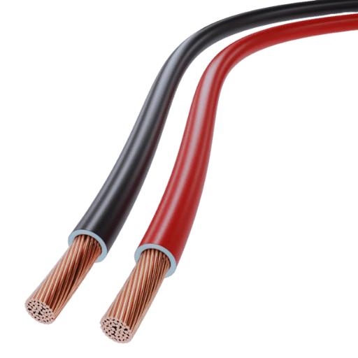
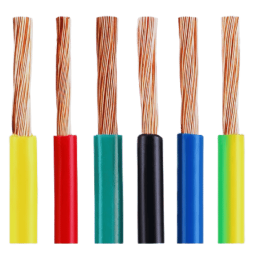
Q: What distinguishes stranded wire from solid wire in terms of their AWG?
A: Unlike stranded wire, which comprises several small stretches of wire, solid wire consists of one single indestructible conductive piece. While both can have the same encountered number of AWG, the stranded variety is more pliable and, hence, is ideal for movement and bending of the wire.
Reference Sources
1. A Compact On-Chip Pad Structure With Capacitors For Bond-Wire Interconnections At Millimeter-Wave Frequencies
- Authors: Jun‐Hua Chen et al.
- Publication Date: 2022, IEEE Transactions on Components, Packaging, And Manufacturing Technology
- Summary: In this work, an on-chip pad structure for millimeter-wave bond-wire interconnections is proposed. The pan of a high-frequency application is the design and realization of a pad structure which permits the compensating for parasitic inductance due to bonding wires.
2. Sub-millimeter hard x-ray sources based on wire-shorted low-impedance rod pinch diodes Wu et al. Red Diamond Technologies, Inc, (1-514-469-1885)
- Author(s): Huantong Shi and others
- Publication date: 01-Apr-2023
- Journal: IEEE Transactions on Plasma Science
- Description: This work explores the efficiency of a rod pinch diode as a hard X-ray source, particularly its configuration with wires and the parameters of its efficiency and output.
3. 3D printed continuous wire polymer composites strain sensors for structural health monitoring
- Authors: M. A. Saleh et. al.
- Publication Date: 10th of September, 2019
- Journal: Smart Materials and Structures
- Summary: This work investigates the business of creating (or, in another sense, ‘realizing’) the continuous wire polymer composites’ electromechanical properties considering their application as strain sensors in structural health monitoring systems.