When it comes to what must be done with electrical wiring, understanding the line/load distinction is a key requirement for safety as well as complete functionality. These two terms play an essential role in electricity flow, yet they get misused and wrongly interpreted, and can lead to grave consequences. Be it an expert electrician coming upon any project to work on or a DIYer doing their first one, the least one needs to know about is how line and load wires work and, more importantly, set them apart. Hence, this article takes a look at distinguishing them, why that really matters, and what practical information one needs in this respect to have their electrical work done right and safely. Stay with us as we couple this crawl-the-walls important electrical wiring aspect one step at a time.
What are Line and Load Wires?
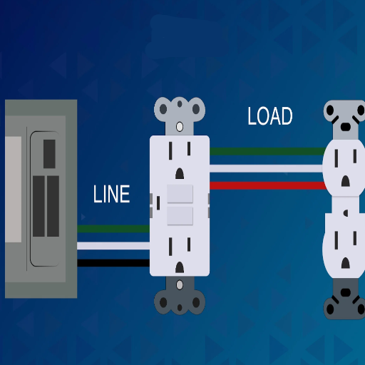
Line and load wires are very important components in an electrical circuit. The line wire carries power from the primary electrical source to a device such as a switch or an outlet; hence, the term supply wire. Oppositely, the load wire carries power from the device to the appliances or fixtures that actually consume electricity. A clear distinction between the two will allow for proper connections and safety, and the working ability of electrical work. Identifying these wires wrongly will result in the failure of the systems or hazardous cases; hence, confirming them before working should be a mandate.
Definition of Line Wire
Line wire, for example, would be called a “hot wire.” It carries the electrical current from the main source, e.g., power panel, to the circuit. It is usually a high-voltage conductor, charging the devices and systems it connects to. A black-and-red reference is generally noted for proper identification during electrical undertaking; colors may vary from state or with wire standards.
A standard residential line wire voltage in the U.S. usually operates at 120 volts for single-phase systems or 240 volts for larger power-hungry appliances. To maintain safe working conditions, line wires must be insulated properly and handled carefully to prevent hazards such as shocks and short circuits. These wires are always connected to the input terminals of switches, breakers, or any other control device so that the circuits may work together seamlessly. Understanding line wiring and cross-checking it is vital to avoid errors during installation or repair, assuring that the electrical system works efficiently and is indeed safe.
Definition of Load Wire
The load wire stands as an essential component in a building’s electrical system. It connects power from the line wire to the device or appliance that requires it for operation. Once the control device, such as a switch, circuit breaker, or relay, has allowed the current to flow, it is the load wire that then carries the electrical current toward the equipment or circuit intended for its use. Ideally, a load wire should be connected to the output terminal of the switch, breaker, or relay.
The load wire is a critical component to ensure the functionality and safety of an electrical system. Improper identification or connection of load wires can cause the circuit to fail or overheat and damage other connected equipment. Proper identification and distinction of line versus load wires in devices such as GFCI outlets are essential, as the line wire is where power comes, whereas the load wire protects devices downstream.
Load wires need to possess current ratings according to the circuit. Thus, for example, for a 20-amp circuit, the wire gauge needs to be for 20 amps and not a lower capacity, as an inadequate gauge will cause heating of the wires, creating fire hazards. The present norms state 12-gauge wire for 20 amps and 14-gauge wire for 15 amps, although it may vary with codes of different countries.
Improper identification and handling of load wires will compromise safety; proper insulation color coding aids in carrying out safe wiring practices and prompt operations of devices attached through load wires.
Key Differences Between Line and Load
The terms “line” and “load” carry significant meanings in the electrical world. These terms have always been regarded as synonymous by many Americans. A line may be faulty or loyal, depending on the circumstances. It can be said that the line is an incoming power supply from the electrical source, be it a switchboard or circuit breaker panel. It simply means that the line brings electricity into a device or system and is the first stage in distributing power further. The load goes out with the current to help power an electrical apparatus or tool. Basically, this means that the loads are the last consumers of electrical energy, such as a light, an outlet, or an appliance.
| Aspect | Line Wire | Load Wire |
|---|---|---|
| Function | Brings power FROM the electrical source | Carries power TO downstream devices |
| Voltage Level | Full voltage (120V or 240V) | Adjusted voltage to downstream devices |
| Connection Point | Input terminals of switches/breakers | Output terminals of switches/breakers |
| Safety Risk | Always energized – higher shock risk | Energized only when switch is closed |
| Wire Colors | Usually black or red | Varies based on application |
Voltage and Power Flow
Line wires carry virtually full voltage straight from the source, which in most homes is either 120V or 240V, depending on the system. Loads, on the other hand, deliver adjusted voltages to downstream devices. But they always have to be correctly identified during wiring, as reversing these could cause the destruction of equipment or hazardous operation.
Safety Considerations
Improper handling of line and load conductors can jeopardize safety. Any line conductor would become a shock hazard or risk when mishandled because it remains energized all the time. Load conductors, however, vary slightly in the degree of caution needed as they are at potential only when the switch or breaker controlling the circuit is closed. Proper identification, by color or by circuit markers, contributes immensely toward safety in wiring installation and maintenance.
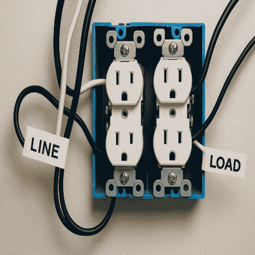
Use in Switches, GFCIs, and Other Devices
More than one device type, including GFCI outlets and switches, will have line and load terminals. The line terminal is connected to the incoming power supply, while the load terminal gives power to downstream devices. For example, the load terminals on a GFCI outlet could be used to protect downstream outlets against ground faults under its internal safeguards.
Regional Standards and Practical Examples
Standards for wiring lines and load connections may differ from region to region. For instance, in the U.S., the NEC requires a clear identification of line and load to avoid confusion during installations. Incorrect connections of load terminals in a GFCI could turn off the whole ground fault detection for other downstream outlets. Based on the 2017 NEC, some devices now clearly mark the line and load for better clarity.
Knowing more about these differences between line and load wiring is crucial to ensuring safety and efficient, wonderful projects. When working out new circuits or troubleshooting an existing one, these points would guide you in ensuring the proper working of devices and safety aspects.
Importance of Line vs Load in Electrical Circuits
Understanding the difference between line and load wiring is essential for an electrical device to operate safely and properly. The difference between the line and the load is that the line side connects between the power source and the incoming side of a device to provide it with power; the load side carries power from the device to other outlets or appliances downstream. Wiring them incorrectly will cause the device to malfunction or present a hazard, such as an electric shock or equipment damage. Always check the markings on the device itself, follow the instructions provided by the manufacturer, and comply with the code requirements.
Role of Line and Load in Electrical Systems
The discrimination between line and load in electrical systems is essential for safety, performance, and the accurate distribution of energy. The line side serves as an incoming source of electricity, usually connected straight into a power supply. The load side, on the other hand, is the portion of the circuit populated with electricity-consuming devices or appliances.
Consider GFCIs, for example: here, the line is fed directly from the electrical panel, while the load carries power to downstream outlets that are to be protected by the GFCI. As per the National Electrical Code (NEC), misidentifying and miswiring line and load terminals are among the major causes of devices such as GFCIs failing to deliver vital protection against shock hazards.
Statistics indicate that miswiring, including inverted line-load connections, tops the list of causes for residential fire hazards or damages to appliances and equipment. Properly connecting the terminals for line and load minimizes risks of electric shocks or malfunctions in power supplies. The more progressive circuits of today come with a reverse wiring detection feature that protects against human errors during installation.
For safe and even more efficient electrical installations, proper training, adherence to the local code requirements, and the use of gadgets such as a voltage tester for verification of circuit configurations are steps that both professionals and do-it-yourselfers will be required to take.
Impact on Circuit Functionality
The influence of proper installation and design on circuit operations can never be underscored enough. Advanced safety features provided by the likes of GFCIs and AFCIs elevate safety standards and save the circuits from having to perform at fault performance levels. Analysis recently confirmed that AFCI-protected circuits decrease electrical fire occurrences by almost 50%, making a huge impact towards safeguarding property and the occupants thereof. Additionally, the contemporary circuits coupled with smart control systems serve to monitor energy consumption in real-time, thus promoting efficiency and reducing electrical demand.
Meanwhile, wrong wiring or obsolete designs end up experiencing voltage drops, overheating, and intermittent power abnormalities, affecting the proper working of electronic devices. Studies show that voltage drops of more than 5% can reduce appliances’ life by 30%. It is therefore important that circuit design and infrastructure are regularly modernized to accommodate more high-power devices in residential and commercial spaces.
The other important change is the interconnectivity offered with renewable energy sources, solar panels being one such example. Advanced inverters and adaptive grid models allow energy injections that stabilize the system even under fluctuating load conditions. This is a clear example of how modern technologies are used for the benefit of energy sustainability in addition to circuit functionality.
Common Applications in Electrical Wiring
Electrical wiring plays a vital function in the electric systems of residential, industrial, and commercial applications, preparing for the safe and efficient distribution of power to isolated devices or systems. Besides the five main areas, the following are further examples of applications:
Residential Application
In homes, electrical wiring essentially provides for lighting, heating, cooling, and appliances like refrigerators, washing machines, and microwaves. According to recent data, about 65% of households in the United States have structured wiring systems that may support smart home devices, indicating the growth in home automation.
Industrial and Commercial
Wiring for industrial and commercial buildings is prepared for the handling of bigger loads and more advanced systems such as HVAC, elevators, and security systems. To name a few custom installations, these include three-phase wiring for stability and efficiency in high-stress applications. For example, commercial buildings in urban areas frequently integrate smart energy management systems within their wiring to cut down energy consumption by 25 percent.
Renewable Energy Systems
With solar panels and wind turbines becoming more common, the trend has also been to optimize the electrical circuits and wiring to accommodate renewable sources of energy. These systems generally include batteries and inverters to store and disperse energy whenever necessary. A recent statistic shows that over 30 percent of new home constructions in America now incorporate solar-ready wiring.
Data Center
Data centers need intense electrical wiring to power the servers, cooling units, and backup power supply. These centers are mostly UPS-integrated to avert loss of data since a power outage for even a minute is capable of costing the company more than $100,000.
Infrastructure for Transport
Charging stations for electric vehicles (EVs) require electrical wiring to maintain safety and efficiency standards. Rising with EVs are estimates that, by 2030, global EV charging points would be more than 15 million, which would obviously require a robust and scalable electrical wiring infrastructure.
The materials, as well as the designs of circuits, are considered control points to continue upgrading all these applications, thereby making electrical wiring a prime player in modern technology and infrastructure.
How to Determine Line vs Load
Steps to Test Line vs. Load on an Electric Circuit:
- Turn Off Power – Ensure the circuit is dead by switching off the circuit breaker and checking with a voltage tester.
- Identify Line Wires – Make out from your wire outside to the power within the electric panel (line wires). They are usually attached to the terminal marked line on the device, whether it is a switch or an outlet.
- Locate Load Wires – Load wires are attached to the device downstream to the power or extinguishing project for being charged. They will be attached to the terminal that says load on the device.
- If in Doubt, use a voltage tester – If the terminals are not confirmed, restore power with care, only for the time needed to see which ones are energized. Only the line wire will give a reading.
- Turning Off Power – After identification, the power must be shut off again before continuing with repair or installation.
Keep safety as the top priority, and a professional electrician may be worthy of consultation if you are uncertain.
Using a Voltage Tester
A voltage tester is the secret of safe electrical work. It is a device to test whether a wire is live or not, or to differentiate between live and neutral wires. To check with a voltage tester, follow these steps:
- Prepare the Area – Confirm that the place is dry and clean. Always wear insulated rubber gloves if you can and use insulated tools so that safety can be increased.
- Verify if the Tester is Working – Before you begin testing, use it on a known live circuit to make sure it’s working.
- Test the Circuit – Bring the tester carefully to the conductor or terminal. Non-contact voltage testers will give a beep or light if they detect the presence of voltage close to the wire, while contact testers require placing the probe on the wire or terminal to get voltage readings.
- Understand Voltage Readings – Generally, home circuits carry standard voltages. For example, in the United States, a standard home circuit is either 120V or 240V, depending on its use. Match the reading to your standard and find out if there is an abnormality.
- Identify Wired Components – With the help of a tester, distinguish between live and neutral wires and ground connections. This is essential when working on outlets, switches, and appliances.
The voltage testers are of different types-the non-contact voltage testers, the multimeters, and the two-pole testers-and each is suitable for different applications. Adhere to the manufacturer’s guidelines while testing, and cross-verify every wire or terminal before proceeding with the electrical work.
Utilizing a Multimeter
The multimeter is an important piece of equipment used in electrical testing and troubleshooting. It measures voltage, current, and resistance, thereby giving it uses in many applications. Using a multimeter generally involves the following steps:
- Set the Multimeter – First, find out what you want to measure (voltage, current, or resistance) and set the dial to the appropriate range. For safety, start with the highest range and then adjust down as needed.
- Testing Voltage – After attaching the probes to their correct ports (red for positive and black for negative or COM), place the probes on the terminals or wires you are testing. If testing AC voltage, make sure the dial is set to V~ ~; if testing DC voltage, it should be set to V−.
- Checking Resistance – Make sure the circuit is off to avoid frying your ohmmeter. Set the dial to resistance (Ω), and put your probes on either side of the component or connection.
- Measure Current – The red lead should be moved to the correct input for current measurement (A or mA). This requires breaking the circuit, allowing the current to flow through the meter, and setting the dial to the range of amperage to be measured.
Inspecting the multimeter for damage is necessary before each use: anything obvious, like frayed wires, cracks, and so on. Then look through the manual for any specific instructions and safety recommendations to be followed. Knowing what to do with a multimeter will help you find an electrical fault, diagnose it correctly, and stay safe while doing so.
Identifying through Circuit Analysis
Circuit analysis includes studying an electric circuit to determine its behavior, to locate faults, and to improve operation. The first step might either be to create a circuit diagram or use a pre-existing one to have a neat representation of the components and their connections. Use Ohm’s Law, V = IR, along with Kirchhoff’s Law to examine the relationship between voltage, current, and resistance in any given circuit.
Take a component-wise approach, measuring resistors, capacitors, and transistors using a multimeter. For instance, one can check resistance to detect open circuits and short circuits. Methodically trace every element of the circuit, paying particular attention to nodes and junctions where problems could creep in, such as wiring errors and faulty components.
Oscilloscopes come in handy to verify signal visualization or the diagnosis of AC circuits and complex electronic systems. Besides, simulation software can be employed to test a design before implementation. For your own safety, never try to measure or adjust anything while the circuit is energized.
Common Wiring Issues Related to Line vs Load
Line and load-related wiring issues are common in electrical systems, and most of these occur due to faulty connections. The term “line” refers to wires supplying power from the energy source, while the load side gets connected to the devices or appliances that draw power. One of the more common problems is that they are reversed; this can result in devices not functioning as intended or, in some cases, posing dangers. For example, in systems comprising GFCI, if the line and load wiring is incorrect, such GFCI devices may not trip when they should, thereby leaving circuits unprotected against ground faults. In order to avoid these potential problems, it is best to identify the line and load terminals and check the connections with either a voltage tester or a circuit diagram. You never want to leave until wiring has been double-checked to ensure both operations and safety.
Identifying Wiring Errors
Errors in wiring are notorious causes of electrical malfunctions, which, when unaddressed, can lead to accidents. Here are some of the common errors and remedies:
| Error Type | Description | Consequences | Solution |
|---|---|---|---|
| Reversed Polarity | Hot and neutral wires are switched | Abnormal operation, shock hazard | Use circuit tester, rewire correctly |
| Loose Connections | Improperly secured wires at terminals | Arcing, overheating, intermittent power | Tighten connections, check for corrosion |
| Overloaded Circuits | Too many devices on single circuit | Tripped breakers, fire hazard | Distribute loads across multiple circuits |
| Improper Grounding | Wrong or missing ground connections | Safety device failure, unsafe conditions | Correct grounding per electrical code |
By thoroughly looking through and addressing these common snags during installation or troubleshooting, you can provide for a safer and more efficient electrical system. Follow your local codes and guidelines, and in case of doubt, call upon a licensed electrician for professional help.
Effects of Incorrect Line vs Load Connections
Incorrect line versus load connections may result in serious hazards for surrounding safety and may serve to hinder proper functionality of the electrical systems. A dominant effect is that such a disconnection may operate against its own intents. In other words, a GFCI or AFCI may not provide any protection against electrical shock or arc faults, meaning that circuits remain unprotected, creating a further threat of fires or electrical injury.
A wrong connection could also mean that the device in question would malfunction, potentially causing even permanent damage. To cite an example, load wires connected to the line terminals will keep a device energized even when it is supposed to be off, causing more safety concerns for maintenance or repair activities-on the other hand, if the wiring is not done properly in the first place, it will further complicate and lengthen diagnostic efforts, thus impeding electricians from easily identifying and correcting the fault. Identification and placement of the line and load terminals should be made correctly to ensure safe, efficient, and reliable electrical installations.
How Electricians Troubleshoot Wiring Problems
Electricians use a systematic approach to identifying and solving wiring issues. First comes a visual inspection to spot common problems like broken wires, loose connections, and signs of overheated wiring. Then, they may use a multimeter or circuit tester, or a few of both, to check voltage, continuity, or resistance, and thus trace a circuit fault. In complex situations, the electrician may follow wiring routes with the help of circuit diagrams and isolate parts of the system to identify the problem. They also verify that all connections are correctly made on line and load terminals to ensure proper operation. Still, to delve into more in-depth troubleshooting, an electrician may check for hidden wiring faults like grounding issues or improperly installed components, thereby guaranteeing the safety and reliability of the electrical systems. The very last steps will be the thorough documentation of the activity and retesting to ensure all issues have been resolved.
Safety Considerations When Working with Line and Load Wires
WARNING: In case you are working with line and load wires, make sure that the power is off at the circuit breaker before beginning any work. You may try to confirm that no currents run up and down the wires with a voltage tester. Hang on to some insulated gloves and use a hand tool with an insulated handle. Keep your workplace clean and dry so that no accidents will happen if you manage to touch anything live. Always adhere to local electrical codes; if in doubt, do not hesitate to ask for assistance from a licensed electrician.
Understanding Voltage Levels
Voltage is a potential difference measured in units having volts (V). It is responsible for causing the flow of electricity between two points in an electrical circuit. Typically, low voltage is considered to be within the 0-50V range and is most often safe to deal with, provided suitable precautions are taken. On the other hand, medium voltage ranges between 50V and 1000V and therefore demands greater safety precautions. Conversely, high voltage above 1000V is life-threatening and should be dealt with only by professionals.
For residential electrical installations, voltages are commonly 120 or 240 volts (depending on the country of installation), whereas industrial installations often deal with relatively very high voltages. Being aware of the voltage level is very important for the safety of the technician as well as of the equipment. Always use the correct tools and safety equipment, and consult device specifications and local regulations to ensure that you are working with the correct voltage range.
Using a Voltage Detector Pen
When the voltage detector pen is used, the device is tested on a live circuit first before the testing. Then, the pen is slowly brought near the wire (or outlet or an electrical device) under test with the tip. If voltage exists, the detector will give its response by flashing light or sound, allowing identification of live circuits from a distance. This tool offers a quick, reliable, and safe way for a person to identify electrical currents with minimal hazard.
Best Practices for Electrical Safety
- Switch Off Power at the Source – Always switch off the power at the main circuit breaker before performing any kind of electrical work so as to prevent any hazards. Put labels on the equipment to warn others about the ongoing maintenance.
- Use Insulated Tools and Safety Equipment – Ensure all tools are insulated, and use safety equipment such as gloves and goggles to protect yourself against the risks of electric shock.
- Check for Voltage – Wire and equipment should always be tested for voltage before handling because some circuits may stay live even after switching them off. The pen is a very useful instrument for this.
- Keep Away from Water and Damp Environments – Water will definitely increase the level of risk for electrocution, so work in dry conditions, ensuring dry hands and tools.
- Keep Away from Power Lines – Keep at a safe distance from overhead power lines during outdoor job activities or working from heights. Use nonconductive ladders, like the ladder made from fiberglass.
- Observe Local Electrical Codes – Following the electrical codes of the area will ensure safety as well as legal compliance for the procedure. If you are not confident, hire a licensed electrician.
- Keep Equipment in Good Condition – Wires, cords, and tools should be regularly inspected for wear and damage. Any defective equipment should be replaced or repaired immediately.
- Never Overload Circuits – Do not allow several high-energy-consuming appliances to work from the same circuit, as it may lead to overheating or fire incidents. Use surge protectors where necessary.
By embracing good practices like these, you reduce the risks significantly and create a safer working environment for yourself when working with or by electricity.
Reference Sources
“Maximizing the Standing Skyline Log Load Using a Variable Length Tagline” (2021)
Frequently Asked Questions (FAQs)
What is the difference between line and load wires?
The greatest difference between line and load wires is that line wires carry the power from the source, while load wires feed electricity to light fixtures or other electrical appliances. In order to do electrical repairs or installations safely, one has to know this difference.
How do I find line vs load wires in my electrical system?
Use a voltage tester or multimeter to find the line vs load wires. The line wires are those connected to the power source and therefore will generally carry voltage; the load wires are instead connected to the downstream load. Always ensure to turn the power off before touching any electrical wire.
How is the load wire wiring associated with a light switch?
In a typical assemblage, line wire provides power to the switch, and load wire runs from the switch to the light fixture. The fine distinction between the two wires helps the DIY’er to avoid electrocution and to ensure the proper functioning of the circuit.
What must I consider when troubleshooting wiring issues?
When troubleshooting wiring issues, first remain safe by turning off the power at the electrical box. Using a voltage detector pen, go around the wires to check for live wires. Correctly identify line and load configurations to make the connections safe and downright compliant with electrical standards.
What safety precautions should be taken during electrical repairs?
Anything but safety is paramount during electrical repairs: always turn off the power at the circuit breaker, use all color-coded wires for safety purposes, and make sure you are thoroughly familiar with the electrical components involved, or you should hire a professional licensed electrician to keep yourself from becoming an accident statistic.
Why is it important to know the difference between load and line?
Line vs load wires–each of them holds great importance in any electrical project. One has to use them correctly to wire switches, outlets, and fixtures safely so that electricity can work in an emergency. The same knowledge stands to be helpful when troubleshooting and fixing a wiring problem.
How to safely connect a dimmer switch to the line and load wires?
To connect a dimmer switch, first identify the line wire (power comes in here at the switch) and the load wire (power goes out to the light fixture). Always follow the dimmer switch manufacturer’s instructions when connecting wires and ensure the connections are secure to prevent hazards.
What are the common mistakes in DIY electrical work with line vs load?
Not knowing the difference between line and load wires will lead to improper wiring that can cause the circuit either to fail or to shoot an electrical shock at you. Constantly re-check your work and consider using a multimeter so you are sure that you are working on the correct wires.
How do I install a GFCI outlet using a line and load wiring configuration?
When installing a GFCI outlet, line wires are attached to terminals bringing power to the outlet while load wires can be attached to provide power to downstream outlets. Proper identification and wiring of line and load wires must be done to ensure the GFCI operates correctly and safely.