In any electrical circuit, the laws of current, resistance, and potential difference govern every bit of behavior within the little moving needles in an apparatus or a much bigger wire movement beneath a dam!-and knowledge about electrical circuits courses through our lives. It is interesting to know about series and parallel circuits if one hopes to be an intrigued learner, an aspiring engineer, or somebody venturing to get an electrical problem fixed. Both of these types of electrical circuits are contemplated based on myriad applications, ranging from the simplest of gadgets to complex electrical circuits. In this article, we will consider each type of circuit in terms of some characteristics and some distribution of current and resistance, and gain practical insight into the role of potential difference. The style of writing that you’ll come to understand better through these explanations is the anchors that hold these indispensable concepts that make up our present-day, technology-driven world.
Introduction to Electric Circuits
Electric circuits are the routes via which electric current flows and hence serve to operate an electronic device and systems. An electric circuit comprises components such as resistance, capacitance, and a power source connected in a manner that controls and directs electricity. There will be two major kinds of circuits: series and parallel. In a series circuit, the components are connected in a single path with the same current flowing through every component. Parallel circuits allow for alternate paths; hence, current flows through various components at once. This understanding of basic principles aids in the design of electrical systems and facilitates troubleshooting.
Definition of Series and Parallel Circuits
Series Circuits
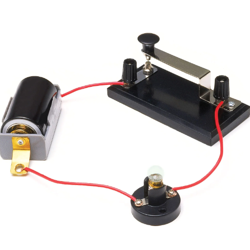
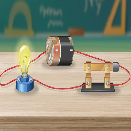
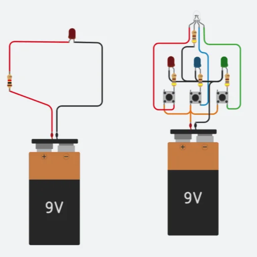
A series circuit is an electrical circuit whose components are connected in a line, one after the other, so that the path for current is single and continuous. This means that the current passes through the components in sequence. If one part fails, the entire circuit is interrupted. The series circuit is typically applied in string light circuits or some simple electrical testing set-ups where all the components have to receive the same current.
Parallel Circuits
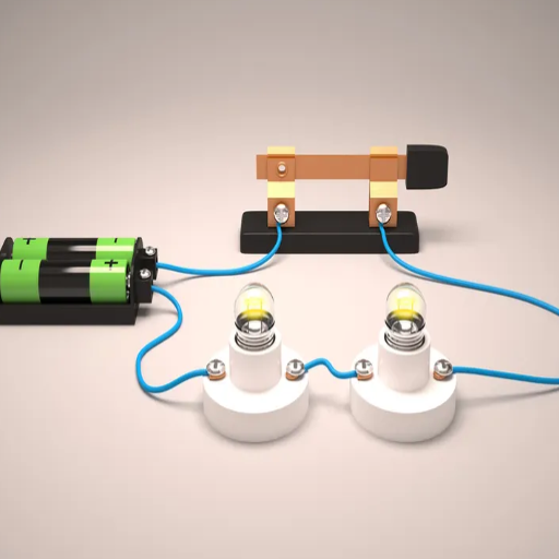
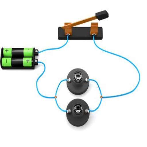
A parallel circuit is an arrangement where various components are connected through multiple branches and thereby provide independent paths for the current to flow. These branches get equal voltages; hence, if a path or a component fails, the rest of the circuit continues working. Parallel circuits find worth in household wiring systems and devices requiring multiple components to function independently.
Both these types of circuits have their respective uses and therefore form the backbone to designing electrical and electronic systems.
Importance of Understanding Circuit Types
There are different types of circuits to understand in designing electrical systems, troubleshooting them, and effectively optimizing. Things work differently for series and parallel circuits- depending on how current and voltage are divided among components. Knowing the difference and when to apply either assists in efficient power distribution, device reliability, and designing for specific requirements. For example, series circuits enable designers to keep the current constant, while parallel circuits grant redundancy and independence to their components, which is crucial in home and industrial applications. Such knowledge aids in energy-efficient and risk-free systems, all while promoting safety standards in the electrical design.
Applications of Series and Parallel Circuits
Series and parallel circuits behave in reverse due to their inherent character. Series circuits are used mostly when constant current flow is required, like string lights or old-style Christmas lights. Since the circuit is a single continuous path, every component receives an equal amount of current. This can be a disadvantage if, for instance, in any component failure, the circuit ceases to function.
In contrast, parallel circuits find widespread application in household electrical wiring because this method allows various devices to operate independently; for example, turning off one light in a room does not affect the operation of other appliances. Parallel circuits then go on to provide a supportive role in redundant systems in automotive and industrial applications to safeguard reliability in the event of a single capacitor failure.
Such circuits are equally crucial to renewable energy systems like solar-panel arrays, where series and parallel circuits are combined to optimize voltage and current generation and usage for easier and more efficient energy consumption and storage, thus making it an indispensable utility in today’s electricity.
Components of Series and Parallel Circuits
Resistor
Resistors are typical circuit elements that keep electric flux from flowing freely. They can be arranged in series, causing an increase in total resistance, or they can be arranged in parallel, thus decreasing the overall resistance.
Capacitors
Capacitors store electrical energy and, depending on the circuit requirements, can be connected in series or in parallel to achieve the needed capacitance.
Power Source
To give a circuit life, a power source from a battery or generator is needed.
Wires
Wires connect different components and allow electric current to flow through them.
Switches
Switches deal with the operation of circuits, turning currents on or off as required.
Components in a Series Circuit
Components connected in series are arranged end-to-end; thus, the current flowing through each component is the same. This setup is employed when a steady current is desired throughout the circuit. Key details and considerations about series circuits are listed below:
Current Flow
The current is the same through all components in series, as there exists only a single path for the flow of current. If this path is interrupted, the flow of current ceases throughout.
Voltage Division
The voltage halved by the source is divided over the respective components in a circuit, e.g., with a 12V battery and three equal resistors in series; this implies a voltage drop of 4V across each resistor. The voltage across each component is calculated in accordance with Ohm’s Law (V = IR), where current (I) remains constant, and resistance (R) is that of the respective component.
Resistances in Series
The total resistance in series equals the sum of the different resistances; if there are three resistors, each having resistances of 2Ω, 3Ω, and 5Ω, the total is calculated as follows: 2Ω + 3Ω + 5Ω = 10Ω. Usually, this results in a considerably bigger total resistance compared to parallel circuits.
Energy Usage
Since voltage is divided, energy consumption among the components is split. Each component converts electrical energy into other forms (such as heat, light, or mechanical energy) proportionally to its resistance.
Uses of Series Circuits
The series circuit is used in applications where uniform current is required, such as Christmas lights or a few older string-light-type gadgets. However, due to their limitations—that one faulty or disconnected device causes the entire circuit to fail—they are even less utilized in this day and age.
Understanding these features of series circuits can help engineers and designers to apply them more effectively in real-life situations, taking into account an improvement in performance as a priority.
Components in a Parallel Circuit
A parallel circuit stands out from a series circuit in that its components are connected across common points or nodes, thereby creating more than one path for current flow. More than anything else, the reliability and efficiency of this type of circuit make it appealing to contemporary electrical and electronic systems.
A major advantage of parallel circuits is that a failure of one component or disconnection will not affect the functioning of other components in the circuit. In modern home wiring systems, for instance, parallel circuits ensure that power loss at one outlet or light fixture will not affect the operation of others. Because of this feature, parallel circuits find applications where reliability is paramount, such as in residential and commercial power systems.
Each branch of a parallel circuit carries its own current according to the resistance and voltage in that branch, while the total voltage across all branches remains the same. According to Ohm’s Law, the current flowing through the branch is calculated by the formula I = V/R, where “I” represents current, “V” represents voltage, and “R” is the resistance. For example, a circuit consists of three resistors in parallel with resistances of 4Ω, 6Ω, and 12Ω, and a voltage of 12V is applied to the circuit. Then currents will be 3A, 2A, and 1A for each of the resistors, respectively, and their sum will be 6A, which is also the total current flowing through the circuit.
In contrast, capacitors in parallel circuits exhibit a combined capacitance equal to the sum of all the individual capacitances. This helps in power supply design, where it makes the power supply better able to smooth out voltage fluctuations.
Thus, parallel circuits find distinct applications in systems of all standards, from household systems to high-capacity industrial setups. Their ability to provide equal power and retain system functionality under variable conditions makes them the backbone of modern electrical design.
Cells Connected in Series vs Parallel
Connecting cells in series combines their voltages, while the current remains the same for a single cell. If three cells of 1.5V are connected in series, the output voltage becomes 4.5V, but the current capacity remains that of just one cell. Series connections are mostly employed when a higher voltage is required, such as in flashlights or battery packs of other electronic devices.
Conversely, cells connected in parallel combine their capacities to provide current but maintain voltage levels equal to a single cell. For example, three cells of 1.5V, with capacities of 2000mAh each, connected in parallel would still provide 1.5V to the load, but at a total capacity of 6000mAh. This kind of configuration is favored for applications that require longer energy storage duration, like power banks and renewable energy setups.
The main difference between these setups lies in the distribution of power. Series connections cater to applications that require high voltage so that specific devices requiring a particular voltage can run efficiently. Parallel connections, on the other hand, increase the operational time of devices by offering continuous power for longer stretches, hence making the parallel setup ideal for devices needing steady power over extended periods.
Hence, when designing and sometimes selecting battery configurations, it is always paramount that the system as a whole or unit has particular needs, such as voltage or capacity demands. Knowing the offsets behind connecting cells in series versus parallel sets the stage for the greatest performance of portable electronics and large-scale power systems.
Current and Resistance in Circuits
Current and resistance are the basis for the understanding of electrical circuits. Current signifies the flow of electric charge through a conductor and is measured in amperes (A). Resistance signifies how well a material opposes the flow of current- the unit used to measure it is ohms (Ω). Ohm’s Law provides a simple relationship between voltage, current, and resistance: ( V = IR ), where ( V ) is the voltage, ( I ) is the current, and ( R ) is the resistance. By applying this law to a circuit, one can analyze how any change in resistance or voltage would affect on current flowing through that circuit. This is very important for the precise design and analysis of electronic components.
Current in a Series Circuit
Current at all points along a series circuit path is equal. Since there is but one pathway for the flow of electrons, the current cannot split or vary: it remains constant throughout the circuit. The calculation for total resistance in a series circuit is straightforward, as it is just the sum of all the individual resistances: R_total = R_1 + R_2 + R_3 + … + R_n. From Ohm’s Law, the current would be a function of the total voltage supplied and the total resistance: I = V_total / R_total. Therefore, the current will increase if either the voltage increases or the resistance decreases. Because the current remains constant throughout a series circuit, these circuits are very easy to study, whereas that very parameter serves as a parameter of failure—the first failure in the series will disrupt the entire circuit.
Resistance in a Series Circuit
This is surely a worthwhile analysis of resistance in a series circuit. It states that the total resistance of all components connected in series is just the sum of their resistances:
1. How is total resistance calculated in a series circuit?
The total resistance, R_total, is equal to the sum of the resistance values of each component in the circuit.
2. What effect does the total resistance have on the current?
According to Ohm’s Law, V=IR, the current flowing through a circuit is inversely proportional to the total resistance. That means, if the total resistance goes up, the current will diminish provided that the voltage remains constant, and vice versa.
3. What will happen if one of the components goes wrong in the circuit?
If that component in the series circuit fails, opens up, or goes bad, it will break the whole circuit and stop the current flow. This is the main disadvantage of a series: the failure of just one component may affect the entire system.
With an understanding of these principles, one can analyze series circuits efficiently and use them where simplicity and predictable behavior are paramount.
Resistor in Parallel: Current and Resistance Implications
When in parallel, the resistors offer lesser resistance, such that the reciprocal of the total resistance equals the sum of the reciprocals of the individual resistances. Thus, the current divides and goes by more than one path; this finally means more total current flowing through the circuit. In the parallel arrangement, the voltage drop across each resistor is the same-they are all connected directly across the same two points. One of the main advantages of the parallel circuit is that if one of the resistors fails, it does not disrupt the entire circuit, and other paths carry current through the circuit uninterrupted. Parallel resistor arrangements find use in electrical systems where performance under fault conditions and proper voltage distribution are paramount.
Potential Difference Across Circuit Components
In analyzing potential difference across components in a circuit, we must take into consideration the type or configuration of the circuit. For a series circuit, the potential difference is divided among the various components in accordance with their resistances, because the current is the same throughout the circuit. Whereas, in a parallel circuit, the potential difference across each component is the same, for all components are connected to the same two points. Thus, understanding design and voltage distribution emerges from these considerations and contributes to crafting an efficient and reliable electrical system.
Measuring the Potential Difference in Circuits
When trying to measure potential difference using a voltmeter, the connection must always be in parallel with the component whose voltage is being observed. The voltmeter measures the energy difference per charge between two points, and the unit for this is volts (V). For accurate reading, a voltmeter must have high internal resistance so that it does not alter the flow of current through the circuit. This potential difference helps an engineer understand how energy is transferred within a circuit, which assists in fault diagnosis or power calculation and eventually the optimization of circuit efficiency. It is very important for an engineer to effectively measure and interpret this difference for any circuit analysis and design.
Potential Difference Across Components in a Series Circuit
Hence, the sum of the potential differences at each element is equal to the total potential difference across all elements. The reason is that in a series circuit, the current flowing is kind of the same, and in so doing, voltages are divided in respect to resistance. Expressed mathematically:
Here, V₁, V₂, and so on are the potential differences across each component, whereas V_total is the potential difference injected into the circuit by the source. The greater the resistance of a component, the bigger its share of the voltage, as stated by Ohm’s Law (V = IR). This is very important in understanding series circuits about energy distribution and is crucial in electrical design and troubleshooting.
Potential Difference Across Components in a Parallel Circuit
In a parallel circuit, the potential difference across any element in the circuit is equal to that supplied by the source, since each branch of a parallel circuit is directly connected to the power source from which it draws its supply. In a series circuit, voltage decreases as it passes through each component; in a parallel circuit, voltages across parallel paths remain equal. This fact allows us to treat components in a parallel circuit more distinctly and is one of the simplest reasons, being parallel circuitry soon comes into use for domestic and industrial wiring.
Series vs Parallel Circuits: Key Differences
| Aspect | Series Circuit | Parallel Circuit |
|---|---|---|
| Configuration | Components are connected end-to-end to form a single path through which current flows | Components are connected across multiple paths so that current divides and flows through each branch independently |
| Current | The current through every component is one and the same because there is just one path | Current flow is split among the branches depending on their resistances |
| Voltage Distribution | Voltage drops across the components are proportional to the resistance of each component; the voltage is shared between the components | Voltage stays the same across every branch; the voltage is equal across the components |
| Resistance | When connected in series, the resistance adds up, therefore becoming large overall | Resistance is less with an increase in more paths, so it is efficient |
| Reliability | Should any component fail, the circuit is opened at that point, which means the disruption of current. A break in a series circuit will stop the current from flowing completely through the circuit | If one branch fails, the other branches are still operational; hence, it is more reliable. Other paths continue to function unaffected |
| Applications | Used in products like string lights, where ease of use is a priority. Series circuits are typically used for simple purposes | Used in electrical wiring systems in the home and machinery, generally favoring stability and consistency. Parallel circuits are used for complex systems, such as home electrical wiring, since it is stable and less affected by operations |
These features separate series circuits from parallel circuits and make them attractive for the differing needs of electrical systems.
Series vs Parallel: Advantages and Disadvantages
Series Circuit Advantages
- Easy to design with fewer components required
- Simple construction and setup
- Cost-effective for basic applications
Series Circuit Disadvantages
- Relies on every component working properly
- Any failure in a component will disrupt the entire operation of the circuit
- Less reliable for critical applications
Parallel Circuit Advantages
- Most reliable and trustworthy design
- Other paths continue to work if one branch fails
- Components operate independently
- Better suited for modern electrical systems
Parallel Circuit Disadvantages
- Take more materials than series circuits
- More time to put together
- Higher initial cost
As far as I see it, series circuits, besides being easy to design and having fewer components, have the advantage of relying on every component working properly. Any failure in a component will disrupt the entire operation of the circuit. In this sense, parallel circuits are the most reliable and trustworthy, as the other paths continue to work if one branch fails. These, however, take more materials and time to put together than series circuits. Depending on the specific electrical system requirements, each type can be used.
When to Use a Series Circuit vs a Parallel Circuit
The choice between a series or parallel circuit rests squarely on the specific needs of the system at hand. Series circuits are ideal when all elements are to carry the same current-voltage drop; for instance, low-power applications like string lights or devices with a single switch controlling many elements. Being simple to design and cheapest in materials makes them an ideal choice for simple applications. However, they are less reliable- since the circuit assumes completion of any working component, any failure in one component stops working of the entire circuit.
Parallel circuits suit systems in which reliability and independent operation of components are most valued. Such circuits are found in residential and commercial systems, where methods such as turning one light or outlet on and off must operate independently of another. Such circuits provide the load with a constant voltage and do not allow failure in one branch to affect the other branches. Although they require more materials, their design complexity is just the price for their versatility and reliability- hence being the choice of most modern electrical systems. So whether or not it will be a matter of simplicity or reliability depends on what the needs of the application are.
Reference Sources
Impact of Series and Parallel Connection of Macro Fiber Composites
Performance Measure of Series-Parallel Circuit Configurations
Promoting Problem-Solving in Electric Circuits via Voltage Tracking
Frequently Asked Questions (FAQs)
What does a series circuit mean?
A series circuit is a kind of circuit in which components are connected in a chain, generating a single path for current to flow. In a series circuit, the total voltage across the circuit is divided up between the components in the circuit, and the total current is equal through each component. When one component fails or is taken away, it breaks the entire series circuit, causing every device to cease working.
What makes series circuits different from parallel ones?
The essential difference between series and parallel circuits has to do with the way they’re connected. Components in series circuits are connected in a single path, so the current flowing through all elements is the same. However, in parallel circuits, the components are connected across the same voltage source, so current can flow down separate paths. This also means that if one component in a parallel circuit explodes, the rest will keep functioning, while in a series circuit, a broken component totally halts the current flow.
How do resistors act in series?
In a series circuit, resistors wired in series create a total resistance equal to the sum of the individual resistances. This greater resistance, in turn, controls the magnitude of current flowing through the circuit as per Ohm’s law. The voltage drop across each resistor is dependent on its resistance, although the same current flows through each resistor.
What is a short circuit?
A short circuit occurs when there is a path that offers low resistance, diverting current away from the actual circuit path and allowing excessive current to flow. This phenomenon may occur in series as well as parallel circuits, but is considered more dangerous in series circuits, as it may damage components or end up becoming a fire hazard. In the case of a short circuit, the circuit is open, and the flow of current goes out of control.
How does one make use of capacitors in series circuits?
Capacitors in series are used to obtain a total capacitance less than that of the smallest capacitor found in the circuit. The formula for calculating the total capacitance for capacitors in series is similar to that for resistors; i.e., 1/CT = 1/C1 + 1/C2 + … + 1/Cn. In line with that, these types of circuits serve functions such as filtering and timing.
Can batteries be connected in series?
Yes, batteries can be connected in series in order to attain a higher output voltage for the storage element in a circuit. When batteries are installed in series, the voltage supplied to the circuit’s terminals is equal to the algebraic sum of the voltages of each battery. This combined voltage is used in situations requiring extra voltages to switch on devices.
What is an example of a series circuit?
An example of a series circuit can be seen in a string of holiday lights. Each bulb is connected in series, meaning current flows through each bulb consecutively. Going further, if one bulb burns out or is removed, the circuit is broken, and all the other bulbs go out. This is to say that components connected in series can greatly impact other radiating operations.
What is the total current in a parallel circuit?
The total current in the parallel circuit is the sum of currents flowing through each component of the circuit. That means while current flows through an individual path of the circuit, the source current outside is bifurcated among the paths. This gives more flexibility to the circuit, as failure to conduct through one path does not affect the flow at other ends of the resistances.
What are the advantages of series and parallel configurations?
In the long run, series and parallel configurations provide the electrical engineer with some flexibility to design systems according to specific requirements. Series systems are easy to implement and are used when the application demands a uniform current to flow in the components. On the other hand, parallel systems provide functioning pathways for the current, improving reliability since components can operate independently, which is a need in rather complex electrical systems.