A 3-way switch is used to operate a single light or electrical fixture at two different places. Be it switching on hall lights from opposite ends or adding functionality to the shared space, knowing the working of a 3-way switch makes all the difference. This article demystifies the wiring and functionality behind 3-way switches, breaking them down into simple and approachable steps. After reading it, you will have a clear overview of how these switches operate, what tools you will need, and some tips on doing it safely and efficiently. If you’re ready to take your home’s lighting into your hands, you have come to the right place—read on!
The 3-way switch design allows two separate locations to control a lighting fixture. Commonly, one finds this switch in large rooms, hallways, corridors, and staircases, where ease of operation is an important consideration. The two switches simply have to be connected to the same light, so the switching action at either point can turn the light off or on. To achieve this, in wiring, special traveler wires are used, connecting the switches between themselves. Understanding how they work helps in troubleshooting and installing, thereby promoting efficient placement in your home.
What is a 3-Way Switch?
Essentially, the 3-way switch serves as one mechanism in a set of devices that enables a light fixture to be manipulated from two distant spots. The design seems to infringe upon the cardinal precept of electric circuit design: the two unique 3-way switches and the light fixture. Travelers constitute the circuitry-their wires carry an electrical current between the two switches from the power source to the load (light).
Key Point: The common terminal is reluctantly distinguished by its terminal screw being darker than the rest of the terminal screws on the switches. The travelers connect the two switches, allowing them to enable different paths for electricity to flow into the load depending on the positions the two are placed in: one path turns on the light when both switches are positioned to allow electricity to flow, the other breaks it when either of the switches is positioned to interrupt the circuit.
Eight Become Modern Wiring Standards Generally Employ 14/3 or 12/3 Cable with a Hot Wire, Neutral Wire, and Two Traveler Wires. Knowing this setup is essential for correct installation and troubleshooting. This system provides a good balance of simplicity and function, hence becoming a dependable solution for multi-point control in homes or commercial spaces. Moreover, with the advancement in smart technologies, 3-way switches are now being integrated with wireless operations for more enhanced controls through apps or voice control.
According to the latest reports, such work can technically improve ergonomics and lighting in staircases, long hallways, or living room areas, thus saving energy.
How a 3-Way Switch Works
A 3-way switch is a sort of switch in which one light fixture or load can be controlled from two places. This is done with a specific wiring arrangement in which there are three terminals on each switch, along with a common terminal. The circuit uses a traveler wire system in which current is passed from one switch to the other to either complete or break the electrical circuit, depending upon the switch positions.
The fundamental components of the switch circuit are two switches, one light fixture, and the power source. One of the two switches has a live wire connected to the common terminal, while the other has the load wire attached to its common terminal. Two traveler wires are running between a second terminal on one switch and the corresponding terminal on the other switch within the circuit. Flipping either switch reverses the traveler connections, thus turning on or off the light regardless of its previous state via the other switch.
Smart 3-Way Switch Technology
Advances in 3-way switch technology have brought along new designs called “smart 3-way switch,” which added wireless connectivity to further its features. In such cases, these smart switches communicate over Wi-Fi or Bluetooth networks, allowing the user to control them either through an app or by voice commands with Alexa or Google Assistant. Some also record an energy usage trend; users could optimize lighting and reduce energy consumption in return. It has been studied that in residential areas, energy-efficient systems, including smart 3-way switches, could cut electricity bills by up to 30%.
Be they regular or smart, 3-way switches will continue to serve as practical and energy-efficient solutions, especially in areas that require versatile control over lighting.
Common Uses for 3-Way Switches
These 3-way switches find utility in residential and commercial buildings in places where the lighting needs to be controlled from more than one location. Here are the most common applications:
- Staircases: Lights can be turned on or off at the bottom or the top of the stairway
- Long Hallways: Allow for lights to be switched on or off at either end
- Open-Concept Living Spaces: Enable continuous control of lighting between adjoining rooms like the kitchen, dining, and living areas
- Commercial Conference Rooms: Switches at multiple entrances for consideration of lighting
- Garden or Driveway Areas: Provide safe and easy-to-handle lighting for places with more than one entry point
Energy Efficiency Note: Recent studies suggest that, in addition to convenience, well-designed multi-location lighting can also promote energy efficiency by reducing unnecessary occasions where lights remain on.
With the integration of modern smart technology, they now possess very important functions such as dimming and remote control, which ultimately make them the core of energy-efficient design.
Components of 3-Way Switch Wiring
Three-Terminal Switches
Each 3-way switch has three terminals: a common terminal and two traveler terminals. The common terminal connects either to the source of electricity or a load; traveler terminals are used to join the two switches.
Traveler Wires
Two traveler wires are provided between the switches to allow current to pass through for traveling purposes.
Ground Wire
This wire is another essential element of the safety mechanism. It channels any excess electrical current to the earth in case of any fault, thus shielding any potential electrical hazard.
Power Source and Load Connections
One switch gets connected to the power source, while the other is attached to the load, e.g., a light fixture.
All these components come together to form a working and dependable 3-way switch system, providing ease and efficiency to lighting control.
Understanding the Switch Box
The box is usually metal or plastic and offers protection for the wiring connections and organization for the components within a 3-way switch system. Inside the switch box come wires, from the hot wire to the neutral wire, the grounding wire, and traveler wires of them making sure they are safely connected via connectors.
Modern switch boxes are made to further electrical system developments. According to industry standards, any switch box should accommodate its wires with adequate volume space, measured in cubic inches. Therefore, for instance, a standard two-gang box can provide around 32 to 36 cubic inches of volume and may hold several switches and wiring as per installation needs.
Safety Requirement: To avert potential electrical hazards, the box must be adequately grounded and meet local electrical codes. Identifying wires inside a switch box can save anyone time during installation or maintenance and minimize incorrect installations.
Knowledge of the layout and function of a switch box will enable a safe and efficient means of controlling lights or other electrical devices, whether by the homeowner or an electrician.
Identifying Wires: Hot, Neutral, and Ground
Working knowledge of hot, neutral, and ground wires in an electrical installation is essential for safety.
| Wire Type | Color Code | Function | Safety Notes |
|---|---|---|---|
| Hot Wire | Black or Red | Carries current from the source into outlets, switches, or devices | Lives in the circuit – can be hazardous if entered without precaution |
| Neutral Wire | White | Completes the circuit, carries unused current back to electrical panel | Ensures continuous flow of energy |
| Ground Wire | Bare, Green, or Green with Yellow Stripes | Provides safe pathway for current under fault conditions | Prevents shock or dangerous damage |
Safety Protocol: Accurately identifying these wires during installation and repair reduces hazards and maximizes system performance. Always make sure the power is off at the breaker and, with working around wiring, use a voltage tester to check for the presence of voltage before commencing work. Without following national and local electrical codes, all electrical work would likely be unsafe and deemed noncompliant.
Importance of Wire Gauge and Type
Wire gauge and the type of wire used are thus vital for the safety and functioning of any electrical system. Wire gauge is the thickness measurement of the wire, and the common way to measure it is by the American Wire Gauge (AWG) standard. The thinner the wire with respect to gauge number, the greater is the current that wire can safely carry without heating up.
Wire Gauge Standards
- 12-gauge wire: Usually used in general household circuits to carry up to 20 amps of current
- 14-gauge wire: May be used in circuits carrying up to 15 amps
Warning: This mismatching of wire and load, wherein a wire of lower gauge size would be used for carrying high current, may lead to excess generation of heat, making the situation a potential fire hazard and resultant failure of equipment.
Wire Materials and Insulation
The wire comes in a multitude of varieties, with the application deciding on the appropriate material and insulation:
- Copper: Preferred for most residential and commercial applications due to superior conductivity and durability
- Aluminum: Lighter and cheaper, but must be used with care and requires special connections to prevent oxidation and thermal expansion
- THHN: Thermoplastic High Heat-Resistant Nylon-coated insulation
- Romex®: Non-metallic sheathed cable for residential use
Choosing the proper wire gauge and wire type ensures the proper working and safety of the circuit as per the electrical codes. For more complicated or heavier-load systems, it would be best to get the suggestion of a licensed professional to help choose combinations of gauge and type of wire.
How to Wire a 3-Way Switch
- Switch-Off-the-Power: Turn the power off at the circuit breaker panel to maintain safety.
- Install First Switch: At the first switch, the black-hot wire coming from the power source is connected to the common terminal of the switch. Next, the red and black traveler wires are attached to the two remaining terminals, and the ground wire is secured to the green screw.
- Run Traveler Wires: Continue running the traveler wires, red and black, and the ground wire from the first switch to the second switch location.
- Install Second Switch: At the second switch, connect the traveler wires to the two brass terminals. Connect the black wire from the fixture to the common terminal. Connect the ground wire to the green screw.
- Hook up the Fixture: Connect the remaining black wire from the switch to the hot terminal of the light at the light. Connect the white (neutral) wire from the power source to the neutral terminal of the light fixture. They should have the ground wires connected as well.
- Test the Circuit: The power gets restored from the breaker panel, and then both switches are tested for operation: The light should turn on or off.
Important: Always ensure local electrical codes are followed, and call in a licensed electrician if there is a doubt.
Gathering the Necessary Tools and Materials
Proper preparation will always be the most important element in achieving any tasks safely and effectively in electrical projects.
Required Tools
- Wire Strippers: Used for stripping the insulating cover of electrical wire. Look for a multi-tool that accepts several wire gauges
- Screwdrivers: A set of flathead and Phillips screwdrivers to tighten or loosen screws on switches and light fixtures
- Voltage Tester: Use a non-contact voltage tester to confirm that no power is being supplied to the circuit
- Needle Nose Pliers: Bend, twist, and manipulate wires for easier and more secure connections
- Electrical Tape: To insulate connections for safety and durability purposes
- Power Drill: For mounting new fixtures or boxes, boring holes or securing components
- Wire Nuts: Ensure secure wire connections and prevent exposure of live wires
- Measuring Tape: Vital for accurately assessing wire lengths and placement of fixtures
Required Materials
- Electrical Wires: Usually 12 or 14 gauges, depending on power needs and local electrical code
- Light Fixture: Compatible with your switches and suitable for the desired ambiance
- Switches: Standard or three-way switches as needed
- Electrical Boxes: New junction boxes if creating new switches or lights
- Cable Staples: Hold wiring along walls and ceilings for neat installation
- Grounding Screws: For fastening ground wires to metal boxes or grounding facilities
Preparation Tip: Once all necessary tools and materials are gathered, organize them within easy reach to streamline the installation process. Remember to choose components rated for your home’s voltage and to double-check compliance with local electrical codes before getting started.
Step-by-Step Guide to Wiring a 3-Way Switch
Step 1: Turn Off Power
Locate the breaker controlling the power to the switches and switch it off. Use a voltage tester to check whether the wires still have electricity in them.
Step 2: Understand the Wiring
Two switches control one light or fixture in a 3-way switch setup. The wiring has three types:
- Traveler Wires (usually red and black): Form the pathway through which the signal travels from one switch to the other
- Common Wire (black): Connects to the light or fixture
- Ground Wire (green or bare): Safety grounds
Step 3: Install the First Switch
Using a screwdriver, attach the wires to the new switch. The common wire attaches to the dark-colored (common) screw, while the traveler wires attach to the brass screws. Attach the ground wire to the green screw. Carefully place the switch in the electrical box and fasten it with screws.
Step 4: Wire the Second Switch
Repeat the operation at the second switch location. Make sure the common wire is attached to the dark colored screw, and the traveler wires are attached to the brass colored screws. Connect the ground wire to the green screw, and then secure the switch into the electrical box.
Step 5: Connect the Light Fixture
At the fixture itself, the common wire coming from the switches is connected to the black wire of the fixture. Securing the connections with wire nuts is advised, and the ground wire must also be secured.
Step 6: Test Your Installation
Once everything has been wired, turn the circuit breaker on. Test the switches now to see if they will work to turn on the light from either of the two locations. If the light acts abnormally, select the breaker again and recheck the wiring.
Success Indicator: By carefully following these steps and any local electrical codes, you will have efficiently wired this 3-way switch for lighting control.
Common Mistakes to Avoid When Wiring
Incorrect Wire Connections
One of the major common faults is in the identification of the traveler wires, subsequently causing abnormal functioning of the switches. Always use a volt tester or a continuity tester to confirm the connections. Also, the wrong connections can act as safety hazards—for example, causing a short circuit or electrical shock.
Using the Wrong Gauge of Wire
The wire being selected is too small with respect to the load capacity of the circuit, which results in the wire getting overheated and may ultimately lead to the wire catching fire. In most cases, for a residential 3-way switch wiring, 14 or 12 gauge wire is adequate; however, always make sure to check the load requirements and also consult the local wiring codes.
Failure to Provide Proper Grounding for the Circuit
Omitting the grounding conductor or securely fastening it is a very common mistake. The absence of ground leaves an electrical surge and fault, less protected. Grounding provides an additional layer to help provide safety from shock upon malfunction.
Not Following Local Electrical Codes
One of the series of configurations is established to ensure minimum safety standards, and if not observed, an unsafe installation may result or penalties may be imposed. For instance, the NEC does specify certain spacing distances required between junction boxes or wiring installations.
Overcrowding the Junction Box
Too many wires in the junction box can cause overheating and make later troubleshooting difficult. To name one, box fill is calculated; hence, a typical single-gang box will usually hold either only a few 14-gauge wires, depending on its cubic inch capacity.
Power Not Fully Turned Off
Wiring a switch without shutting the power off at the circuit breaker is a hazard to safety. Any lapse, albeit momentary, can cause grievous injuries or even damage to the equipment.
Prevention Strategy: Planning all the wiring carefully, double-checking connections, and observing safety procedures will go a long way toward eliminating these common errors. Larger or more complex installations should provide an electrician to ensure the safety and viability of the work.
Electrician Tips for 3-Way Switch Installation
Installing a 3-way switch can pose a few challenges, but these brief suggestions can help lessen the difficulties:
- Be aware of the wiring diagram: Acquire basic knowledge of the standard wiring for a 3-way switch. One side usually has a common terminal and two traveler terminals, and the other side has the same
- Turn off power: Switching off the power at a circuit breaker is important since, in case of accidental contact, very serious injury may occur
- Label wires: Label the wires common, traveler, and ground; otherwise, it could give rise to confusion during installation
- Have Your Tools Ready: Make sure to have the testing tools, snipping tools, wire strippers, and screwdrivers to do the job efficiently
- Check all connections: Make sure all wire connections are tightly clamped inside the terminals
- Testing: After installation, carefully switch on the power supply and test your switches to ensure that they are operating correctly
Professional Advice: In any case of doubt, a consultation with a licensed electrician can provide guidance that guarantees safety and local code compliance.
Choosing the Right Location for Your Switch
Switch positioning is amongst the most sought-after aspects in terms of function and access. Here is a list of factors to consider:
Height Requirements
Generally, it’s normal for such switches to be placed at a height of 48 inches up to 52 inches from ground level so that they can be easily reached by most individuals, including children and persons with limited mobility.
Accessibility Considerations
The switch should be placed near doorways or in such a way that it is easily accessible from the entrance-exit points to the room.
Functional Purpose
Think of what the function of the switch is and what it is going to control. A switch for overhead illumination should be located close to the main entrance of the room, while switches for appliances or maybe mood lights can be positioned in more context-specific locations.
Clear of Obstacles
Consider the switch is to be set into a wall, which obstruction, like furniture, cabinets, or other fixtures, would prevent access to. Hence, it must be accessible with no obstructions, something which greatly improves usability.
Code Compliance
Always check your local building codes or relevant authority to verify that the placement of the switch conforms to safety and legal requirements; this is especially important where the home needs are for the handicapped.
Planning Tip: Planning for accessibility will ensure ease of use, meet accessibility requirements, and provide an extra bit of convenience in your space.
Safety Precautions When Working with Electricity
Working with electricity requires care to avoid accidents and injury. Here are some very important safety tips that must be followed:
Essential Safety Guidelines
- Power Off: Always turn off the power at the breaker before performing any electrical work. Test the circuit using a voltage tester before starting to ensure that no current flows
- Right Tools for the Job: Insulated tools are to be used, and rubber-soled shoes are to be worn, thereby reducing the shock hazard. Avoid working with damaged or worn-out tools
- No Water: Never work with electricity under wet conditions, near water. Ensure that your hands, tools, and surroundings are all completely dry
- Inspect Wiring: Examine the wire and connections for serious damage or wear. Any wire that is frayed or exposed should be removed and replaced at once to avert short circuits or shocks
Additional Safety Measures
- According to Local Regulations: Always adhere to building codes and electrical standards, especially when electrical systems are being installed or modified
- One Circuit at a Time: In order to remain grouped and safe, work on one circuit or electrical area at a time so you do not confuse yourself
- Use Protective Gear: Safety goggles and gloves when working with larger projects to keep hazards at bay-sparks being an example
- Know Emergency Procedures: Should an accident occur, acting fast is crucial. Know how to panic exit or shut down the main power source
Safety First: If these tips are observed, you will reduce risk and work safely on electrical projects in your home or in other environments.
When to Call a Professional Electrician
With some simple electrical jobs, a homeowner can safely conduct these and work on things. In certain situations, however, a licensed professional electrician is required to ensure that the work is safe, compliant, and done efficiently.
Critical Situations Requiring Professional Help
Circuit Breakers Tripping Repeatedly
If your circuit breaker tends to trip fairly often, it could mean serious issues of circuit overloads or faulty wiring. As the Electrical Safety Foundation International (ESFI) reports, persistent problems of an electrical nature can enhance the risk of electrical fires, which in turn are said to contribute to nearly 51,000 fires in the US annually.
Flickering or Dimming Lights
Initially annoying, flickering lights might signal problems such as loose wiring, overloaded circuits, or voltage fluctuations. These require a correct diagnosis with proper tools and the knowledge of professionals trained for this.
Burning Smell or Scorched Outlets
Maybe it is just a passing burning smell or scorch marks near the outlets. Either way, it surely means something; wires should be overheating, and that is a fire hazard. Professionals will be able to trace the issue back to its source and fix it safely.
Installing or Upgrading Electrical Panels
Major upgrades, such as the installation of a new circuit breaker panel or even upgrading the existing one, require the knowledge so as not to breach building code. Other complexities might include preparing for future energy demand, such as charging stations for electric vehicles.
Old Wiring
As a matter of extreme urgency, any house with aluminum or knob-and-tube wiring must be inspected by and repaired or replaced by a professional. According to the National Fire Protection Association (NFPA), one of the primary causes of electrical fires is outdated wiring in these older homes.
Wet Area Electrical Work
Works in wet areas, such as bathrooms, kitchens, or outdoor outlets, carry a higher risk of electric shock. Professionals must ensure that the area is properly grounded and that ground fault circuit interrupters (GFCIs) are properly installed, which is very important for safety in damp or wet environments.
Permits and Code Compliance
Electrical jobs such as major rewiring and installation of new systems require permits and are governed by strict local codes. Being a licensed electrician keeps him/updated on these laws and codes, to keep the whole work legal and safe.
Investment in Safety: By recognizing these situations, homeowners can hire a professional at the correct time and avoid the risks of, say, electrocution, fire hazards, and costly repairs. An investment in expert help is an investment in the property and indeed in long-term peace of mind.
Troubleshooting Common 3-Way Switch Issues

Being able to recognize common problems and potential causes in 3-way switch troubleshooting is essential.
Lights Not Turning On or Off Properly
Cause: Loose wiring or incorrect wiring is a common cause.
Solution: Check wires to ensure they are tightly connected to their correct terminals-common, traveler, and ground.
Switches Perform Intermittently
Cause: Inconsistent performance is typically caused by worn or damaged switches.
Solution: Check for signs of wear and replace the switch if it is no longer functioning.
Switches Do Not Control the Light Properly
Cause: Wrong wiring would be the main cause here.
Solution: Check that the common wire is connected to the right terminal, as improper connections might cause erratic operation.
Flickering Lights
Cause: Flickering lights might indicate poor contact within the switches or an issue at the fixture.
Solution: Tighten loose connections and check the fixture for damage.
Both Switches Must Be Switched On/Off
Cause: This might happen when the traveler wires are not properly attached.
Solution: Make certain the traveler wires are properly fastened to the traveler terminals of both switches.
Important Note: These kinds of problems almost always arise from improper installation or loose wires. Should the problem continue, contact an electrician to remove further hazards to life and property.
Identifying Problems with Circuit Connections
Loosening of connections, damage to wiring, or just merely an overloaded circuit are some factors causing circuit-wise problems. Based on data gathered in recent years, roughly 51,000 electrical fires take place every year within U.S. homes, mostly due to faulty wiring and bad connections. Early identification of such defects can, on one hand, prevent any potential hazards and, on the other, improve the life of the electrical system.
Common Connection Issues
- Loose Connections: Cause dim or flickering lights, or intermittent power presence. Can be remedied by tightening screws on terminals or ensuring wire nuts fit perfectly
- Overloaded Circuits: Result in interrupting circuit breakers. Usually happen when too many high-power-demanding appliances are on the same circuit
- Damaged Wires: Safety danger where insulation is thinner or cracked by moisture, pest ingress, or physical wear
Modern Detection Tools
For modern systems, faults can be identified better with advanced tools such as thermal imaging cameras and circuit analyzers that pinpoint heating wires or abnormally flowing current. Keeping systems and processes efficient requires the proactive inspection of potential electrical problems using these sorts of detection tools.
Prevention is Key: Keeping wiring in good shape requires timely inspection and prompt replacement or repair of deteriorated wiring. Traditionally, it is a good practice for most consumer markets to use wires of high quality and good insulation, as well as regularly inspecting wire terminals for reliability.
How to Fix a Malfunctioning 3-Way Switch
The basic process when a 3-way switch is malfunctioning starts with turning off the power at the breaker panel for safety. Then, the covers are unscrewed, and the switches are taken out of their wall boxes. Reviewing with a voltage tester, I determine no current is flowing. The wiring connections are then examined; all wires must be tight and secure and attached to the proper terminals. Where I find any loose wires or any damaged wires, I strip the ends, twist them securely, and attach them again. The switches are then reassembled, power is turned on again, and testing the switch ensues to confirm the glitch is gone.
Using a Multimeter for Troubleshooting
In diagnosing electrical problems in circuits, switches, and wiring, an ideal tool is a multimeter.
Multimeter Setup and Usage
- Select the Correct Setting: Choose voltage, resistance, or continuity, depending on what you are testing
- Voltage Testing: Put your probes either on the terminal points or across the circuit to measure current flow
- Resistance Testing: Make sure to have your component out of the circuit, then place the probes at either end to verify it meets resistance specifications
- Continuity Tests: Check if a circuit is intact; a beeping sound or a reading indicates a good connection
Safety Warning: Remember to switch off the power when checking either resistance or continuity, as having the power on may result in damage to the multimeter or perhaps harm to you.
Interpreting Results
Proper interpretation of readings can help isolate the fault—e.g., broken wires, failing components, or loose connections—making repairs much easier.
Conclusion
Understanding and properly installing 3-way switches can significantly enhance the functionality and convenience of your home’s lighting system. From basic wiring principles to advanced troubleshooting techniques, this comprehensive guide provides the foundation you need to work safely and effectively with 3-way switch installations.
Remember that while many homeowners can successfully complete basic electrical work, complex installations or persistent problems should always be handled by licensed professionals. Safety should never be compromised for the sake of cost savings.
Whether you’re upgrading to smart switches, troubleshooting existing problems, or installing new circuits, the principles and procedures outlined in this guide will serve as your roadmap to successful 3-way switch implementation.
Reference Sources
Frequently Asked Questions (FAQs)
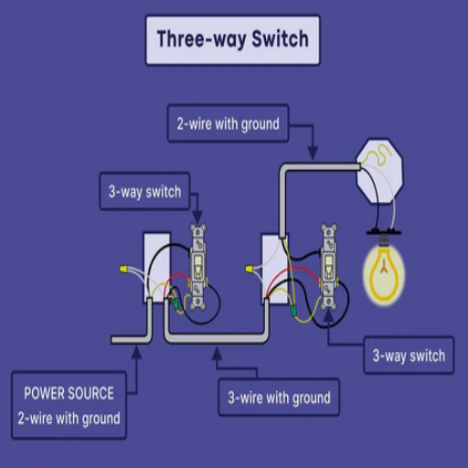
What is the 3-way switch wiring diagram?
A 3-way switch wiring diagram informs one on how to connect three-way switches to control one light fixture from two locations. It generally shows the disposition of all wires, including those for line, load, and travelers, for easier visualization of the working of the circuit.
How to wire a 3-way switch with 3 wires?
Using 3 wires to wire a 3-way switch involves connecting the black wire coming from the power source to the common terminal of the first switch and using the two traveler wires for the traveler terminals. At the second switch, wire the traveler wires back to their terminals, and the common terminal to the fixture. Be sure to properly mark the white traveler wire with tape to indicate its use as a hot wire.
How do you run a 3-way switch circuit?
To work with a 3-way switch circuit, you start by locating the two switches and one light fixture. Now, the cable used could be either a 14/3 or a 12/3. In this cable, one sheathing holds three wires: black, red, and white colors, plus one bare copper ground wire. One would connect the black wire to one side of the power; the red and white wires are then run to the traveler terminals of the two switches. The common terminal of the second switch is connected to the light fixture.
What does each switch do in a 3-way circuit?
In a 3-way switch circuit, each switch provides control of a light fixture from two different locations. Each switch can either complete or hamper the circuit to allow or disallow the light to be turned on or off, regardless of the position of the other switch. This versatility is one of the reasons a 3-way switch system is highly sought after.
What purpose does a traveler wire serve in 3-way switch wiring?
The traveler wire functions as a wire carrying current between the two switches in a 3-way setup. When one switch is flipped, power is sent down the traveler wire to the other switch so that it can toggle the state of the light fixture. Understanding the traveler wire function is critical in wiring a 3-way switch.
Can I run a 2-wire cable for 3-way switch wiring?
No, one should not use a 2-wire cable for 3-way switch wiring simply because it lacks the wires needed to connect the two switches and the light fixture properly. A conventional 3-way switch setting requires at least three wires (two travelers and one common) to work properly and safely. Always use the correct wiring to ensure proper function and safety.
The positive wire in a 3-way switch setup is called what?
Solved in a 3-way switch setup, the positive wire is usually the hot carrying current from the power source. It is normally black, connecting to the common terminal of the first switch. This is so that the positive wire is correctly identified in order to ensure the safety and proper wiring of the circuit.
How can I troubleshoot a 3-way switch wiring problem?
To troubleshoot a 3-way wiring problem, begin by looking at all connections at the two switches and the light. Check for loose wires, incorrect connections, or damaged parts. Test with a multimeter for continuity and voltage, and compare to the wiring diagram to verify. If the problem checkpoints remain inconclusive, having a licensed electrician troubleshoot the issue may be in order.