Your choice of wire type for an air conditioner installation or upgrade is essential for proper functioning and safety. Each type of wiring has its own electrical specifications, which, if not met, may create safety problems like system failure and overheating. This article seeks to share professional information on the types of wires appropriate for air conditioners, their applications, and their installation procedures. No matter if you are an advanced service person or a do-it-yourself homeowner, you will find this article useful in understanding and making sure your system works safely and properly.
What is the Right Wire Size for an Air Conditioner?
Selecting the correct wire size for an air conditioner unit depends on the unit’s electrical needs, more specifically, its amperage and voltage. Residential air conditioning units typically use a 10 or 12-gauge wire, but this depends on the model and specific power demands. It is important to check the manufacturer’s specifications or user manual to find the exact wire size necessary. Choosing the appropriate wire size for the unit is important in avoiding overheating, ensuring safe usage, and meeting codes for wiring. Observe local construction codes alongside building codes; it is suggested that you contact a licensed electrician for the correct installation.
Understanding the Wire Gauge: From 10 to 3 Wire Types
The wire gauges constitute a system of measuring the thickness of electrical wires, which directly relates to their current capacity. When compared to a 12-gauge and thinner wire, 10-gauge wires are thicker and can manage higher current loads. Conversely, 3-gauge wires are much thicker and are categorized as heavy-duty wires for use in industrial equipment and large-scale installations. Selecting suitable wire gauges can help streamline operations while simultaneously following manufacturer recommendations and electrical code policies. Always make sure to check the required gauge depending on the specific voltage and amperes needed for the work.
Calculating the Voltage Drop for Proper Installation
Voltage drop is defined as the decrease in voltage level for an electric circuit resulting from the current flowing through in a circuit and the resistive properties of the wires. Voltage drop is computed as follows:
Establish the Parameters:
- The electrical current in the circuit (amperage).
- The overall distance of the wire, including the return path (from the power source to the load and back).
- The gauge of the wire and its resistance for each unit length.
- Use the system voltage.
Employ the Voltage Drop Formula:
- \[
\text{Voltage Drop (V)} = 2 \times \text{Current (I)} \times \text{Resistance per Unit Length (R)} \times \text{Length of Wire (L)}
\]
Verify Acceptable Limits:
- A drop of voltage in most circuits should not be more than 3% for safe operation of devices and efficient functioning of system. For more sensitive installations which are located far away from the voltage reference point, even stricter caps may be instituted.
Choose Correct Wire Diameter:
- If in the previous step the output voltage drop was too great then it is necessary to change the wire to a lower gauge thicker wire to decrease resistance.
This should guarantee that the circuit operates while ensuring compliance to the electrical code standards. If calculations add up and checks do not, consult an electrician.
How Ampacity Affects Your Wire for Air Conditioners
Ampacity has a critical relevance in determining the size of wire that an air conditioner requires. It is the measure of the maximum electrical current that a wire or cable can carry before the conductor’s temperature rises to a dangerous level. In cases where a wire’s ampacity is less than the air conditioner’s demands, the wire will reach dangerous temperature levels, which can result in fires or breakdowns. For safe operation, a wire must be chosen whose ampacity exceeds that of the air conditioner’s rated current. Always consult the manufacturer’s recommendations and local electrical standards to establish appropriate wiring guidelines.
How do you install Wires for air conditioners safely?
Steps for Running a 240v Circuit
Check the Electrical Panel’s Capacity
- Prior to commencing work, check the main electrical panel to confirm that it can accommodate an additional 240v circuit. Check that the panel has sufficient amperage and physical space for a double-pole breaker, which is required for 240v circuits.
Collect the Tools and Materials
- In addition to tools such as a voltage tester, wire stripper, drill, and screwdrivers, ensure that you have all the required materials, which include a double-pole circuit breaker fit for the air conditioner, junction box, conduit, and fitting connectors, as well as appropriately gauged wire (commonly 10 or 12 AWG depending on the load).
Switch Off the Power to the Panel
- Prior to the installation, and for safety, switch off power to the electrical panel. Use a voltage tester to verify that there is no active power on the circuits which you plan to work on.
Set Up the Circuit Breaker
- Put in place an appropriate double-pole breaker for the appliance’s circuitry and follow the steps recommended by the manufacturer in conjunction with local electrical codes. Place the breaker in any open slot, and snap it securely into place.
Run the Electrical Cable
- Depending on the air conditioner’s specifications, utilize the correct rated cable, such as 10-3 or 12-3 NM(non-metallic sheathed) wire. Extend the cable from the panel to the air conditioner’s disconnect box or junction box. In case wiring needs to traverse walls or other barriers, use a drill to create proper ports of entry and passage and route the cable through conduits where additional protection is needed.
Connect Wires at Both Ends
- In the panel, connect the wires to the breaker and the associated ground bar. Connect the black and red wires to the appropriate breaker terminals, the white wire to the neutral bar if one exists, and the bare copper ground wire to the bus bar designated for the ground. At the air conditioner disconnect box, the wires must be terminated as per the device’s terminal design. Always refer to the specific air conditioner wiring diagram to avoid any errors.
Secure All Wiring
- Ensure that there are no loose sections of wire and that every exposed wire is covered. These tasks can be completed with the use of wires clamps or conduits. Such care will eliminate the potential danger of damaging the wires and provide long-term security.
Examining and Testing the Circuit
- Post the installation’s completion, check the entire circuit for relative connections, loose ends, bypassed fittings, and compliance with relevant codes. At the end, turn on the power switch at the panel, and with the use of a voltage tester or multimeter, check if the terminals of the air conditioner have adequate voltage and if everything functions as it is meant to.
In this manner, you can securely and suitably set up a 240V circuit for your air conditioner. As always, seeking advice from a licensed electrician or an inspector is encouraged if there are doubts about the installation or to ensure compliance with local electrical legislation.
Importance of Proper Grounding in Air Conditioning Units
Proper grounding of air conditioning units is critical both from the safety and operation system aspects. Grounding, in my opinion, offers an alternative pathway for electrical faults which minimizes the chances of shock or fire danger. Moreover, it protects sensitive unit components against surge voltages or electrical interference which may damage or impair functioning. In my opinion, grounding practices are more than a rule followed in regulation; it is a basic prerequisite for ensuring safety and reliability of an air conditioning system.
Adhering to Local Electrical Codes During Installation
Abiding by local electrical codes during the installation of any air conditioning system is crucial when it comes to safety, effectiveness, and durability. These regulations are put in place to reduce potential dangers such as electric fires, shocks, and equipment failures. Professional safety organizations estimate that around 31,000 electrical fires occur each year in the United States. Often, lack of compliance to standards is a primary reason.
Among the compliance aspects, proper use of wiring, regional standards for cables and connectors, adequate grounding, circuit protection as well as cross protection measures must be in place. For instance, several regions require the installation of GFCIs into a basement or outdoor areas because of wet floors to prevent electric shock. Moreover, adhering to codes mitigates the chances of voltage and frequency mismatch overloads, phase mismatches, and other control grid malfunctions.
Besides safety, compliance aids in conserving resources and protecting the environment. Today’s electrical policies are often in step with conserving energy, such as the driver consummation of high-efficiency systems or renewables. In the United States, professionals need to learn the National Electrical Code (NEC). It is updated frequently to keep up with technology and industrial requirements. During installation, meeting compliance requirements is not only a legal issue, but also a matter of safeguarding public health and safety as well as maximizing system economic efficiency.
Why is Choosing the Right Wire for Air Important?
Impact of Wire Size on AC’s Voltage and Amp Draw
The performance and efficiency of an air conditioning system (AC) is directly related to the size of wire used. If the wire used is too small, there will be considerable voltage drops which will force the AC unit to draw higher amps to compensate. This can result in heating issues, increased energy costs, and damage to the components of the system. On the other hand, AC systems with correctly sized wires ensure proper voltage and current flow, enabling safe and efficient operation. Following the recommendations of the manufacturers accompanied by electrical codes is extremely important when calculating wire size.
How Conductor Material Affects Current-Carrying Capacity
As we have established, a conductors current carrying capacity CCC is highly determined by the material used to fabricate the conductor. The most common used conductor materials in wiring systems are copper and aluminum, and they differ in the properties that affect electrical performance.
Copper Conductors
Copper is very much sought after due to its exceptional electrical conductivity properties. Its conductivity almost reaches up to 58 MS/m (mega Siemens por meter), which is higher than many other metals when it comes to copper transmission. Also, due to Copper’s low electrical resistance, it can carry more current with less energy loss, which is very ideal in cases where minimizing voltage drop is necessary. Its predominant thermal conductivity also aids in further dissipating heat from the current, enhancing CCC. In terms of a 10 AWG copper wire in free air situations, ampacity with regards to surrounding temperature and insulation type typically stands between 30-40 amps.
Aluminum Conductors
Aluminum is used widely due to its lightweight and cost-effective nature despite having slightly lower conductivity than copper. With a conductivity of about 36 MS/m, aluminum performs at about 61% of copper’s conductivity. This means that aluminum wires need to be around 1.26 times larger than copper wires to achieve the same CCC. For instance, while a 10 AWG copper conductor has a CCC of roughly 35 amps, an equivalent aluminum conductor would need an 8 AWG-sized aluminum conductor to achieve the same CCC. Aluminum conductors are most beneficial in industrial and utility-scale applications where weight and material costs are the sole focus.
Impact of Temperature on Various Materials
Copper and aluminum both are sensitive to temperature changes, which impacts their CCC. Low temperatures are favorable as CCC increases with decrease in temperature. Copper does show better thermal stability as the material retains its structural integrity and strength under high temperatures. Higher temperatures are not beneficial for aluminum. It expands and contracts more than copper, increasing the risk of connection loosening over time. Termination and mechanical considerations become crucial for aluminum to maintain a safe and efficient operation.
Key Considerations in Material Selection
The conductor material choice needs to be consistent with the application needs, such as electrical load, type of environment, and the available budget. For higher-performance applications, copper is preferred due to its greater current carrying capacity (CCC) and reliability, while aluminum’s benefits for cost means it is suitable for projects on a large scale where material costs dominate. Respecting safety and building codes like NEC (National Electrical Code) policies are also very important in defining what type of conductor is suitable for the system and the dependability of the electrical system.
Avoiding Overheating and Tripping the Breaker
To prevent overheating issues along with tripping the breaker, ensure that the electrical load is not exceeded beyond the circuit capacity. Calculate load demands accurately, conforming to the National Electrical Code (NEC) stipulations, and utilize circuit breakers of appropriate ratings. Routinely evaluate the condition of wiring and connections because their deterioration can result in overloaded circuits and overheating. Be sure to not overload the outlets; if possible, use multiple circuits and spread the electrical devices throughout. These factors, combined with proper maintenance, will eliminate overheating concerns and ensure issues do not arise.
What are the Different Wire Types for Air Conditioners?
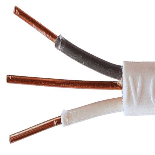
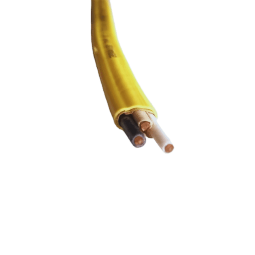
Exploring the Differences: 10/2 vs 10/3 Wire
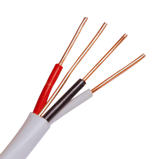
The number of conductors is the primary distinguishing factor between 10/2 and 10/3 wires. A 10/2 wire has two conductors which include a hot, a neutral, and a ground wire. 10/3 wire has a greater number of hot wires which are both insulated along with a ground wire and a neutral, giving it a total of three conductors.
Because 10/2 wire is used most frequently for air conditioners and water heaters, which only require a voltage of 240 volts, it does not require a neutral connection. In contrast, the 10/3 wire is used for appliances that run on dual voltage and need a neutral such as modern heat pumps, enabling cooler air during warmer months. The choice always depends on what equipment is in use as well as what voltage and wiring is needed. Compliance with local electrical codes and the equipment manual should always be verified.
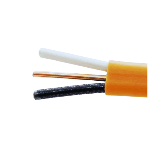
Role of Insulated Wire in HVAC Systems
Insulation is an important aspect of wiring which contributes to the safety and working efficiency of HVAC systems. Within an HVAC system, the wiring harness must be insulated to guard against shock, short circuits, and fire risks due to moisture or damage. Furthermore, the wiring must be properly insulated to ensure it does not overheat due to excessive voltage and current placed on it by the system.
Although new models of HVAC systems are more energy-efficient, their complexities and advanced features need to account for even greater voltage variations in the wiring used. For instance, R-2-rated HVAC wires have been known to use grade R2 due to the capability it has to withstand high temperatures, often above 90°C (194°F). This is important because HVAC systems are subject to internal heat generation from operation, particularly in the compressor and motor circuits.
Moreover, the specific HVAC wire insulation material used affects the wire’s protection and longevity. Due to their heat, moisture, and chemical damage resistance, thermoplastic (THHN or THWN) and cross-linked polyethylene (XHHW) are common choices for HVAC wires. Research indicates that during prolonged system operation, wires with higher-grade insulation can minimize energy waste by up to 10%, underscoring the optimal HVAC energy performance principles alongside sustainable practices.
HVAC wiring ignoring the appropriate standards or lacking proper insulation can create system inefficiencies and, quite detrimental, warranty breaches, highlighting the need to follow prescribed wiring guidelines. It is critical for professionals to comply with manufacturer-provided insulation specifications and general wiring guidelines, observe the NEC, and prioritize safety and optimal efficiency.
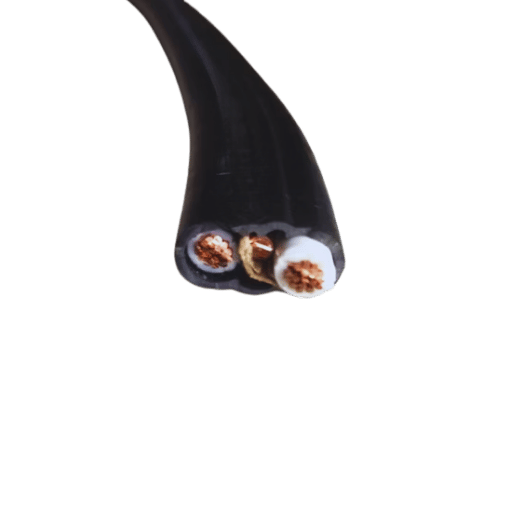
Using Conduit for Enhanced Wire Protection
Conduits play a very important role in shielding HVAC wiring from damage, moisture, and other environmental factors. It provides electrical wires with a pathway that minimizes the chances of corrosion, abrasion, and unintentional contact. With NEC compliance, properly mounted conduits minimize risks of potential electric faults, thus improving safety. EMT, PVC, and flexible conduits are metal and non-metal options suited for specific installation and design needs. Failure to comply with building regulations and local codes will cause problems if the wrong type of conduit is selected.
How to Determine the Required Power Supply for Your AC Unit?
Calculating the Power Supply Needs for Central Air and Window Air Conditioners
Estimating the electrical power requirements for an air conditioning (AC) unit needs particular attention due to its impact on system efficiency, safe operation, and avoiding circuit overload conditions. This task requires consideration of the unit’s electrical parameters alongside the available electricity supply.
Central Air Conditioning Units
The primary limitation in the installation of central air conditioners is the availability of electricity. Central air conditioning systems usually have high electrical supply requirements because of their high cooling capacities. Most of the systems work on 208/230 volt circulatory systems and can draw 15-60 amps depending on the tonnage of the unit. For example, a 2.5-ton central AC unit may draw 30 amps, so the circuit breaker needs to be rated at 30 amps. The unit’s power parameters are often available on a data plate and are usually given in terms of “minimum circuit ampacity” (MCA) and ”maximum overcurrent protection” (MOP). In planning the power supply, stepper motors always have to provide a safe operating limit.
Window Air Conditioning Units
Window air conditioner systems consume less energy than central air systems do, so they are easier to control within smaller spaces or for secondary use in larger spaces. Air conditioners designed for smaller spaces, such as rooms, usually require 5,000 BTU of cooling capacity, which roughly needs a 115-volt outlet and consumes around 500-700 watts. Larger models, such as 12,000 BTU units, may need 230 volts and consume as much as 2000 watts. Confirm the amperage rating on the dedicated circuit, which normally sits at 10-15 amps for smaller units and ranges up to 20 amps for larger units.
Important Aspects Of Electrical Systems
Size of the Breaker and Its Wires:
- The wires assigned for each circuit breaker need a proper rating per the units’ specifications. If the wiring and associated brokers are not ideal, there could be issues of overheating and even fires.
Voltage Rating:
- Check if the voltage marking of the AC unit aligns with the electric system of your home. Cross checking the voltage rating is crucial as it could cause irreparable damage to the equipment.
Energy Efficiency Ratings:
- Check if the AC unit comes with SEER (Seasonal Energy Efficiency Rating) or EER (Energy Efficiency Ratio) because they minimize power usage while maximizing cooling output.
Through the analysis of these factors, an electrical configuration tailored to your AC system’s specifications can be designed while guaranteeing maximum safety and performance.
The Role of a 240-Volt Setup in Home Improvement
High-demand appliances in contemporary households are powered using a 240-volt setup, particularly central air conditioning units, electric dryers, and ovens. Using a 240-volt system minimizes the amount of electrical current drawn, reducing energy loss and improving safety due to better load distribution. These systems allow larger appliances to be powered at optimal performance and energy efficiency. When a qualified electrician performs the installation, safety standards, and reliability are ensured.
Ensuring Proper Receptacle for Your AC Unit
Always cross reference the voltage and amperage of your AC unit’s receptacle, ensuring they match requirements. Typically, most residential AC units operate on a 120-volt or 240-volt receptacle depending on AC unit’s size and power specifications. Find these requirements either on the manufacturer’s guidelines or on the unit’s label. Also, make sure that the outlet and circuit are dedicated only to the AC unit in order to avoid overloading. For safety reasons and proper compliance with electrical codes, have a licensed electrician install the required receptacle.
Frequently Asked Questions (FAQs)
Q: What size wire is needed for a home air conditioning unit?
A: With regard to home air conditioning units, especially the 220 volts ones, there is a recommendation of using a 10 gauge wire so as to prevent overheating from the electrical load. Additionally, ensure to add a proper grounding conductor for safety reasons.
Q: How do I determine the proper gauge wire for my AC?
A: The appropriate wire dimensions are based on the air conditioner’s voltage and amperage rating. For example, if it is a 30A circuit on 220 volts, it typically has a 10 gauge wire. Make sure to check the specific requirements mentioned on the AC’s nameplate.
Q: Is it alright to use lower gauge wire for my AC?
A: It certainly is not alright. Using lower gauge wires than suggested will create the danger of overheating as well as compromising safety. In order to ensure optimal performance of one’s air conditioner, it is important to use wires that can sustain the current without overheating.
Q: What purpose does a grounding conductor serve in air conditioner wiring?
A: The purpose of a grounding conductor is to improve safety by channeling the ground electrical faults, thus lowering the chances of electric shocks as well as fires. This is very important in residential and commercial technical work.
Q: What are the differences between wiring an air conditioner on a 110v versus a 220v circuit?
A: A 110v circuit is usually single hot wired with a ground for lower power units, like mini splits, while a 220v circuit has two conductors plus ground to accommodate, and larger units have higher power loads caused by larger units.
Q: Does an air conditioner circuit require a GFCI?
A: An additional measure such as GFCI is not mandatory but could reduce electrocution ground faults outside or near wet areas.
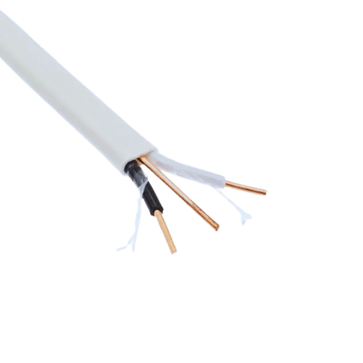
Q: What is needed to wire an air conditioner with three conductors?
A: A three conductor wiring is usually two power supply cables/lines and one grounding wire, this setup is common in large units on 220v circuits so they are able to safely manage the electric power demand.
Q: How can I be sure the wire will withstand the electrical load of my air conditioner unit?
A: The model of the air conditioner gives information about its power supply requirements and electric currents necessay for using a wire frame with sockets allowing smooth movement without causing any poles to overheat.
Q: What steps should be taken from a safety perspective while setting up air conditioner wiring?
A: Make certain the connections are not loose, the wire used is of the correct gauge, and a grounding conductor is included. Observe all local safety codes and installation requirements for the equipment and related systems to mitigate risks during installation and usage.