Modern communication systems rely on coaxial cables which have a vital function in transmitting high-frequency signals with low interference. The 50-ohm coaxial cable is commonly used in RF communication, wireless networks, and lab testing. Despite these common uses, not all 50-ohm coaxial cables are alike; differences include the ability to maintain impedance, inflexible and flexible construction, power handling, and others. This article will present the various 50 Ohm coaxial cables, their features, and important factors that must be considered when selecting a cable. If you are a telecommunications expert, developer, enthusiast, or any other professional, this guide allows you to make the best decisions based on your technical needs.
What Makes a 50 Ohm Coax Cable Different?
What makes the coaxial cable with an impedance value of 50 ohms special is that it is tailored to facilitate the greatest power transfer and lowest signal degradation in high-frequency settings. This value is preferred for RF (radio frequency) systems, which include wireless communications, antennas, and broadcast systems. The cable’s precision construction ensures uniform performance with minimal interference, thus, making it highly trustworthy in professional and industrial applications. The 50-ohm standard is among the most popular in RF engineering because it balances power handling capability and efficiency.
Understanding Impedance in Coaxial Cables
The term “impedance” associated with coaxial cables means the alternate current flow opposition expressed in ohms (Ω). This characteristic is essential for maintaining an adequate level of signal quality by minimizing loss and distortion. The impedance values of 50 ohms and 75 ohms stem from specific applications. For example, RF communication utilizes 50 ohm cables because they offer adequate levels of power handling and efficiency, while for video signals, 75 ohm cables are preferred because these cables minimize attenuation of the signal over long distances. Correct selection of impedance guarantees the proper functioning of the system.
The Role of the Dielectric in Signal Quality
Signal quality is affected by the dielectric because it controls the speed and efficiency of signal transmission. As I see it the dielectric material affects the capacitance of the cable and the ability to propagate signals through it. Effective dielectric materials diminish losses and reflections which enhances signal transmission. By selecting the appropriate dielectric I am able to maximize the performance of a system while preserving signal integrity throughout the many applications.
Conductor and Shield Materials
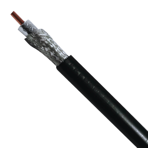
Fiber shielding, as well as conductors, require specific materials which assist with the performance and efficiency of a cable system. For instance, conductors are primarily made of metals such as copper or aluminum, which have superior conductivity. Oxygen-free copper has an increased electrical conductivity of approximately 5.96 x 10^7 S/m. In addition, tinned copper also poses upgrades in durability and oxidation resistance, thus achieving better signal transfer.
Braided copper and aluminum foil, along with a combination of both, are used for shielding. Copper braid shields pose a strong defense against electromagnetic interference but only cover 65%-95% that can be flexible based on application needs. Aluminum foil shields have high potential interference cove coverage, thus making them good for superior foil coverage. Moreover, some wires portray flexibility and full coverage by using a copper braid covered by foil.
The selecting of conductor and shielding materials should consider signal precision, protection from external interferences, mechanical flexibility, as well as cost. Changing alloys to newer and lighter metals allows for advanced engineering solutions. Structural changes in material science improves conductor and shield performance, making modern cabling solutions more efficient.
How to Choose the Right 50 Ohm Coax Cable for Your Needs

Deciphering Different Cable Types
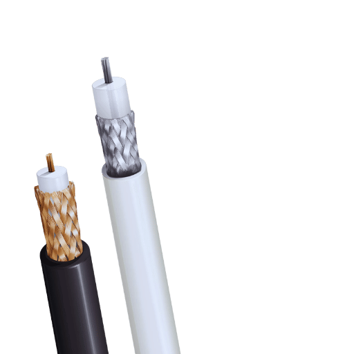
For a proper selection of 50 Ohm coax cables, one must know all types of cables and their applications. Coaxial cables have a central conductor, a dielectric insulator, shielding, and an outer jacket. However, differences in any of them can change performance. Below are some key cable types commonly used for 50-ohm applications:
RG-58
Suitable for general use and short range signal transmission is a lightweight and portable coax cable RG-58. It is around 0.195 inches in diameter and has signal loss of 12.3 dB/100 feet at 400 MHz. It is a common choice in radio communication as well as laboratory testing. As with all coaxial cables, RG-58 intendeds to strike an appropriate balance between cost and performance and is often an optimum choice where moderate flexibility is needed.
RG-400
Also known for its diverse applications: aerospace, military, and high-end communication systems uses, RG-400 is an excellent choice as it does not lose more than 6.5 dB per 100 feet at 400 MHz and maintains strong signals. It is truely an unparalleled coax cable used in extreme environments due to its extreme temperature-resistant PTFE insulation and double shielding, a feature that also enables it to maintain low signal loss. Its durable construction protects it from extreme environments. Its temperature performance underlines the superiority of RG-400.
LMR-195
Engineers will appreciate the enhanced specifications of LMR-195 – an ultra-low loss cable which is mechanically and dimensionally retro-compatible with RG-58. WGC harmful Gg emitters and GPS-powered devices see great benefits due to its signal attenuation performance, which stands at ~6.5 dB per 100 feet at 400 MHz, making it ideal for use in wireless communication.
LMR-400
High-range altimeters often require low-loss, long-range cables, and the LMR-400 excels at both. Significantly over ander equating to a mere 3.9 dB over 100 feet at 400 MHz, it has become a favorite amongst cellphone cellular infrastructure builders. Due to its high conductivity and successful check-in of outdoor antenna systems, the LMR-400 is used in satellite communication and networking applications.
RG-213
With applications in low loss RF logistics, RG-213 boasts a diameter of 0.405 inches, showing just how thick this cable is, alongside its reinforced shielding. Tested RG-213 features great HF radio rupture resistant eclipsed at made for forewarding UV signals, effectively degeging it to serve as a day and night withstanding ultra durable outside ports designed for lateral competetions.
Key parameters examined when considering a cable include factors such as environmental conditions, frequency of operating range, shielding efficiency, and circuitry bounding attenuation, the most favorable one for the entire framework. Assuring that the aim and urgency receive the tubs meets the utility instead of overspending over unwanted expenses.
Factors to Consider: Attenuation and Signal Loss
Attenuation describes the signal strength reduction that occurs as it propagates through the cable. Reconciling attenuation, a low-loss cable should be used if the operating frequency is high or the distance of transmission is long. Factors such as the length of the cable, the quality of the material, and outside disturbances also affect loss of signal. The use of properly designed shielded cables with appropriate impedance minimizes system inefficiencies and enhances the integrity of the system signal.
Evaluating Power Handling Capabilities
A cable’s power handling capabilities pertain to its ability to transmit power without overheating or causing damage to its performance. Such estimation is only possible by evaluating the cable’s power rating which is a function of its construction, insulation and operating frequency. It is mandatory to make certain the cable rating is higher than the power that will be supplied by the system to ensure safety and reliability. For precision, one should refer to the manufacturer’s specifications and ensure that the operating values are within the design values of the cable.
What Are the Applications for 50 Ohm Coaxial Cable?
Use in RF Applications and Transmitting Signals
The performance characteristics of 50-ohm coaxial cables as and radio frequency (RF) systems are very crucial in RF applications and signal transmission because of the precision its functions offer. These cables are built for efficient power transfer over diverse frequencies with minimum signal loss and impedance mismatch. The 50-ohm impedance of RF systems is regarded as a standard because it offers manageable power capacity at low signal attenuation.
Their most common uses are in wireless communication infrastructure and devices such as cellular networks, radio transmitters, and Wi-Fi routers. 50-ohm cables, for example, serve base stations antennas for mobile networks, where signal fidelity is critical to high-speed data transmission. Moreover, they are often used with test and measurement equipment such as spectrum analyzers and RF signal generators because of the fidelity of their signals.
RG58 and LMR-400 coaxial cables, for instance, are 50-ohm coaxial cables proven fit for use at multi-GHz frequencies or above, as indicated in the technical specifications. To illustrate, professional grade systems which operate at or near a GHz prefer the LMR-400 due to its lower loss of 6.6 dB at 100 exposed feet. Such cables incorporate additional electromagnetic interference (EMI) shielding, resulting in better signal quality even in high EMI environments.
An example of a high quality 50-ohm coaxial cable is RG58. Its diverse capabilities coupled with strong signal transmission and reception make it invaluable in modern communication technologies.
The Importance of Antenna Connections
Reliable connections to antennas are indispensable for proper signal send and receive in communication systems. They enable the movement of electromagnetic energy to and from the Transmitting or Receiving unit and the antenna impacting the signal qualitatively and quantitatively. Proper care of the connection guarantees low signal interference and loss, thereby ensuring data and system accuracy. Avoiding poor fixes and using connectors of good standards will enable success in every communication setup.
Utilizing 50 Ohm Coax Cable in Ham Radio
The 50-ohm coaxial cable is a common and important part used in ham radios. Its versatility provides a remarkable combination of power handling capabilities while simultaneously offering low signal degradation. Coaxial cables serve as transmission lines linking a transceiver to an antenna, which preserves signal strength over long distances. The specific value of the characteristic impedance of 50 ohms is optimal for radio frequency (RF) applications, efficiently transmitting power while reflecting minimal amounts, which could otherwise weaken system performance.
Perhaps some of the most notable features of 50-ohm coaxial cable include the extremely low attenuation rates at popular amateur radio frequencies between HF (3-30 MHz) and VHF and UHF band sets (30-3000 MHz). As an illustration, a standard RG-213 cable used in ham radio configurations has an attenuation of roughly 0.65 dB/100 ft at 100 MHz which means that most environments will have limited signal degradation. Moreover, the LMR-400 cables also surpass traditional RG cables in not only having lower attenuation but also improved shielding against electromagnetic interference (EMI).
The versatility and strength of 50-ohm coaxial cables is an added benefit for both portable and fixed installations of ham radios. Modern versions of the cables use better materials like polyethylene and foam dielectric which improves the insulation and increases the power-handling capacity to support high-output transmitters. Shielding configurations, which range from braided copper to aluminum foil, improve protection against external noise which is critical in densely populated or high RF environments.
Cable selection must account for an appropriate length, frequency of use, and environmental factors. For example, low-loss cables like LMR-400 or Heliax are better suited for longer runs due to their signal preservation capabilities. And preservation of performance during fluctuating weather conditions is ensured with weather-resistant or UV-rated coatings.
Ham radio users can achieve optimal efficiency, low interference, and dependability of long-range communications by using professional-grade connectors on high-quality 50-ohm coaxial cables.
Why is 50 Ohm Coax Cable Preferred in Commercial Applications?

Balancing Lower Loss and High-Speed Transmissions
In the commercial sector, 50-ohm coaxial cables are a common sight due to how well they balance signal loss and data transfer rates. They are optimized for high frequencies like cellular, data center, and radio communication because of their minimal reflections and power loss.
Such systems, like 5G, require precision cables and 50-ohm coax does quite well with power handling and signal loss. For long-distance transmissions, cable losses should be manageable, and 50-ohm coax cables provide just that while maintaining signal fidelity. Attenuation rates as low as 0.1 dB/m to 1 dB/m and supporting stable signal transmission at high frequencies up to 10 GHz or more demonstrate prowess in these cables.
Their adoption is further bolstered by the coax’s compatibility with other readily available RF amplifiers, antennas, and test instruments on the market. Modern 50-ohm cables also feature advanced shields along with improved dielectrics making them resistant to electromagnetic interference and preserving the signal in noisy environments.
With that strategic combination of high-speed capability and low-loss performance, 50-ohm coaxial cables have become an integral part of reliable, high-performance commercial communication systems.
Ensuring Compatibility with RF Coaxial Connectors
An RF coaxial cable connector and cable must be matched to coaxial cables of 50 ohm common impedance used in RF systems. Check that the connector is of suitable type, for example SMA, N-Type, BlNC, and that it is appropriate with the cable requirements. Also check that the mechanically assembled parts are tight to avoid increased signal loss due to poor connection. To avoid these errors, one advised to use parts from well known companies and observe the instructions provided during installation.
Common 50 Ohm Coax Cable Types and Their Characteristics

Exploring Popular Models: RG-58 and LMR
RG-58 Coax Cable
An RG-58 is a commonly used coaxial cable of 50 Ohms of resistance for its light weight and flexibility. It is usually applied in radio communications and small scale networking for low power signal transmit. This cable is good for short distance signaling and covering frequencies of up to 1 GHz, but due to higher signal attenuation over longer distances, it is best suited for short range installations.
LMR Coax Cable
These cables have been categorized as high-performance 50 Ohm options tailored for preserving signals. Examples would be LMR-400, which fit under this category. These cables have low signal loss characteristics along with durable construction making them ideal for wireless infrastructure, GPS, advanced broadband systems, and many more. These cables are absolutely perfect for the outdoors as well as long distances due to their resistance to environmental factors.
Spotlight on Low-Loss Cable Options
Having robust, low-loss cables is important for preserving the integrity of a signal over long distances and challenging situations. Below are some of the possible options:
- LMR-400: A cable that is well-known and extensively used for the wireless communication of signals. Also, wireless applications are used because of their weatherproof nature and low signal loss features.
- RG-6: Quite common in satellite and television systems. Also, it is effective in loss of signal and quite compatible with household setups.
- RG-11: Thicker cables to allow low signal loss. Most useful for runs with long cables, high signal frequency ranges, or phases of greater distance.
Make sure to take into consideration the environmental factors, distance range, and operating frequency of a region so as to guarantee the best performance while loss of signal is concerned.
Applications for UHF Connector Systems
UHF connectors are employed in a number of industries due to their usefulness and steadfast performance in radio frequency (RF) connections, which are dealt with under various applications. Given below are some of the most common areas of application for these systems:
Amateur Radio Communication:
- UHF connectors are extensively employed in amateur radio for interfacing transceivers with antennas and amplifiers. These connectors guarantee reliable RF connections for the VHF and UHF frequency bands (up to 300 MHz).
Commercial Broadcasting:
- A good proportion of commercial broadcasters make use of UHF connectors for appliances working on the lower frequency bands. They are optimized for rapid assembly and provide robust connection features which improves their performance for antennas and transmission equipment.
Military and Defense Systems:
- Durable broadcast-grade equipment uses UHF connectors for military communication devices owing to their reliable performance. The tough construction of these connectors guards them against damage due to extreme environmental conditions.
CB (Citizens Band) Radio:
- For casual communication in a CB radio system, UHF connectors are used widely as they facilitate the transfer of RF signals between the transceivers and mobile antennas with great effectiveness.
Testing and Measurement Equipment:
- UHF connectors find a wide range of applications in preparing laboratory grade measuring instruments where connecting the testing equipment requires precise matching of impedance for reliable measurements.
Antenna Arrarys and Installations:
- UHF connectors are the chosen RF connectors for antenna arrays that are cost-sensitive and need reliable performance because the signal frequency is UHF band compliant.
RFID Systems:
- Some readers and other peripherals use UHF connectors as part of the design for their operations in low-frequency fields.
Automotive Communication Systems:
- UHF connectors may be employed for the external antennas of the vehicles using RF communication systems for fleet management or intercoms.
In the case of UHF connectors applied to these systems, focus should also be placed on the operational frequency range, power levels, and ruggedness to environmental conditions in the connectors, considering the overall system’s performance.
Frequently Asked Questions (FAQs)
Q: What is a 50 ohm cable, and what are its common uses?
A: A 50 ohm cable refers to a coaxial cable with a characteristic impedance of 50 ohms and is utilized in mobile land radio, broadband and microwave systems, signal boosters, and VHF radios.
Q: How does a coaxial cable 50 ohm differ from other ohm cables like 75 ohm cables?
A: Coaxial cable 50 ohm is used for RF transmissions, whereas 75 ohm cables are used for television and video signals due to their lower loss characteristics over longer distances.
Q: What are the benefits of using a low-loss cable in coaxial applications?
A: As the name suggests, low-loss cable has reduced signal loss over more distance, allowing for more efficient electrical signal transmission. This is vital for maintaining signal strength, especially in commercial installations and broadband systems.
Q: How do jumper cables function in a coaxial system?
A: Jumper cables are simply short coaxial cables that serve to interconnect various parts of a system, for example, the signal booster and the modem. They offer connection versatility in a system configuration while maintaining proper signal integrity.
Q: What role does the center conductor play in a coaxial cable 50 ohm?
A: Cables that have a coaxial configuration have a center conductor, which is its most important part. The center conductor will always achieve signal reception and transmission. Materials and manufacturing techniques used in the construction of the center conductor should allow the passage of signals with minimal loss.
Q: Why are male-to-male coaxial cables used in certain applications?
A: Male-to-male coaxial cables are applicable when there is a requirement to join two female jacks. These types of cables enable passage of electrical signals by joining the instruments as is the case with Ethernet and VHF radios.
Q: What are the characteristics of RG58 cable?
A: RG58 is a kind of coaxial cable that has a 50 ohm impedance, which is mostly used in RF and signal-boosting applications. Its construction includes a metal shield and insulating materials that cause nonacceptable levels of degradation to the signal, thus suitable for commercial and some domestic installations.
Q: What impact do insulation and shielding have on the performance of an ohm cable?
A: On an ohm cable, insulation, and shielding serve to prevent external interference and signal drain, thereby protecting the transmission of electrical signals. This is critical to the operational efficiency of systems like microwave systems and land mobile radios.
Q: What specific factors must be noted concerning the use of coaxial cables in the installation of a signal booster?
A: With regard to signal booster installations, it is necessary to use low-loss coaxial cables to ensure minimal signal degradation, appropriate interfacing with compatible jumpers, as well as adequate shields on the cable to eliminate the possibility of external interference degrading the boosted signal.
Reference Sources
1. Final report on APMP supplementary comparison P1-APMP.EM.RF-S3: APMP comparison of 50 ohm coaxial mismatches
- Authors: Kamlesh Patel et al.
- Year of publication: Read More » 2012
- Summary: This paper describes the measurement comparison of complex reflection coefficients from six national metrology laboratories in a coaxial system with frequencies 50 MHz, 2 GHz, 10 GHz and 18 GHz. The participating laboratories provided satisfactory feedback in terms of value agreements and equidistance gaps for all values reported were less than the uncertainties associated with laboratory values at a 95% confidence level(Patel et al., 2012, pp. 01013 – 01013).
2. International comparison GT-RF 75A4: reflection coefficient in 14 mm/50-ohm coaxial line at 0.5 GHz, 3 GHz and 7 GHz
- Author: U. Stumper
- Year of publication: 1994
- Summary: This paper summarizes from an international comparison of measurements of the complex reflection coefficient in a 14 mm/50 ohm coaxial line at the designated frequencies. From the study it is seen that the standards had very low drifts for the reflection coefficient over nine years and at the same time there was high consistency among the mean values given by the different participants(Stumper, 1994, pp. 288 – 289).
3. A New Broadband 50 OHM Coaxial- to 1 OHM Microstrip Transition for Superconducting Thin film Devices with Low Input Impedance
- Authors: M Daginnus et al.
- Publication Year: 1991
- Summary: The authors describe the implementation of a new transition, which consists of a 50 Ohm coaxial line transitioning to a 1 Ohm microstrip line using a three-step microstrip quarter-wave transformer. The transition resulted in low losses in transmission for given frequencies(Daginnus et al., 1991, pp. 693–698).