








Selecting wire size is a safety concern and a performance enhancer in the realm of electricity. Load-carrying circuits require proper wire gauge for efficient conduction, avoiding excessive heat, and preventing electric hazards from damaging your house or workspace. Any seasoned electrician or a layman in the workforce who wants to do some DIY should know the relationship between amp, wire gauge, and material. Herein, we discuss what factors go into choosing the right wire size for a 60-amp circuit, breaking down those hard-to-grasp concepts into simpler explanations. By the time you’re finished, the insight brought forth will empower you to take on the task in a way that ensures the safety of your entire setup while being reliable.
Introduction to Wire Size and Amperage
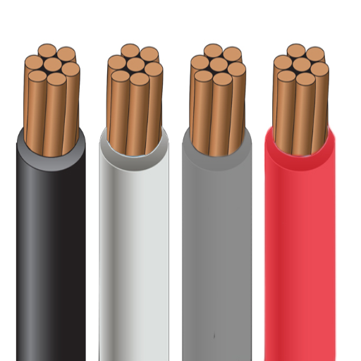
The wire size choice, just as with a 60 amp circuit, is essential for safely carrying electrical current. Usually, for a 60 amp circuit, the typical wire size is maybe a number 6 copper wire or number 4 to an aluminum wire. Copper is considered top-notch for conductivity and the wire’s lifetime, while aluminum is just a light and cheap option. The local electrical codex and standards may sometimes apply to your case and even installation conditions, so check. Using proper wire size protects from the dangers of operation, overheating, and eventuality of electrical disruption.
⚠️ Safety First
Always consult with a licensed electrician and follow local electrical codes when working with electrical systems. Improper wire sizing can lead to fires, electrocution, and equipment damage.
What is Wire Size?
Wire size refers to the diameter or thickness of an electrical conductor, which is usually copper or aluminum. While measuring wire size, a standardized system is utilized, for instance, AWG, or American Wire Gauge. Wire size is important, as the size determines how much current the wire can safely carry and pass without overheating or damaging the wire or electrical system. The larger-sized wire has the resistance low and can carry more current, whereas the smaller ones are meant for low-current applications.
For instance, 14-gauge wire is commonly used in most general lighting circuits because it can carry up to 15 amps, whereas 12-gauge wiring is used for outlets and circuits that carry up to 20 amps of current. Heavier appliances such as electric water heaters, ovens, or air conditioners might require 10-gauge or even 8-gauge wires to carry high currents.
In situations where the separation of the source and load is sufficiently large, voltage drop should be accounted for since smaller conductors can cause considerable voltage drop over long distances. For this particular consideration, larger wire sizes are considered ideal. The size of the wire should always correspond to the load it is carrying and meet safety standards so as not to create any hazards like overheating, fire, or circuit inefficiency.
Importance of Amperage in Electrical Circuits
Current and amperage are two crucial concepts that determine and influence the safety aspect of electric circuits. Amperage refers to the flow of electric charges through a conductor, measured in amperes (A). Too little or too much amperage in a circuit can cause irreparable damage to electrical components, overheating, or even fire hazards.
A household circuit can commonly be rated at 15 or 20 amps, depending on wiring and breaker code specifications. An excess of 20 amps may cause the breaker to trip, wires to overheat, and unsafe conditions to arise. Appliances are designed with specific amperage requirements, and using the wrong amperage will hinder performance or cause a malfunction. For example, larger appliances such as dryers or refrigerators may require dedicated circuits of 30-50 amps to operate reliably and safely.
Also exploited are recent developments in technology and energy efficiency to enable a new product that operates at lower amperage for peak performance. Thus, energy-efficient technologies have come into the limelight. Calculating the proper amperage aligned with load requirements ensures energy efficiency, a longer lifespan of equipment, and lower odds of circuit failures. In designing circuits with engineering precision, electricians and engineers utilize the formula I = V/R. The current (I) equals voltage divided by resistance.
Overview of 60 Amp Circuits
A 60-amp circuit is widely used in residential, commercial, or light industrial settings to support a heavy electrical load. These circuits are used primarily to supply appliances, subpanels, or any other heavy-load equipment like electric water heaters, ovens, or EV chargers. The conductors used for 60-amp circuits are generally 6-gauge copper wire, depending on the distance of the run, for safety and efficiency purposes.
The capacity offered by a 60-amp circuit can be harnessed for up to 14,400 watts on a 240-volt circuit (amps multiplied by volts). However, since this can be a continuous load, safety standards restrict the maximum load to 80 percent of the circuit’s rated capacity, which amounts to 11,520 watts.
In the installation or repair of the 60-amp circuit, one has to ensure compliance with local electrical codes and the NEC for further protection and conformity. Equally important is the selection of circuit breakers, wires, and connections that are appropriate for the particular use of the circuit, ensuring that no overheating or other faults occur. The 60-amp circuit will harness a significant amount of power. It will therefore be considered an excellent option for electrical power. At the same time, its larger capacitor makes it a very flexible option for residential and commercial applications worldwide, which have increasing energy needs.
Determining the Appropriate Wire Size for a 60 Amp Circuit
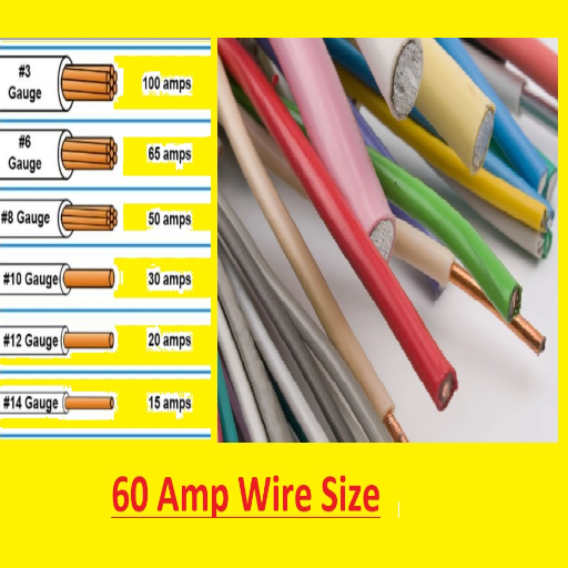
When safely wiring a 60-amp circuit, it is a 6 AWG copper wire or 4 AWG aluminum wire that needs to be run. Copper wiring is generally preferred because it has better conductive properties and lasts longer; however, aluminum wire might be just fine and is significantly cheaper. The insulation temperature rating and voltage rating should be selected for the operating voltage and environmental conditions. Check the National Electrical Code (NEC) and your local building laws and standards to confirm proper compliance before installation.
| Wire Material | Recommended Size for 60A | Ampacity Rating | Advantages | Considerations |
|---|---|---|---|---|
| Copper | 6 AWG | 65 Amps | Better conductivity, longer lifespan, easier connections | Higher cost |
| Aluminum | 4 AWG | 65 Amps | Lighter weight, lower cost | Special connectors required, expansion concerns |
Wire Gauges Explained
Wire gauges are standardized measurements used to determine the diameter of electrical wire and, in turn, its current-carrying capacity. The American Wire Gauge (AWG) system is the most commonly implemented method in the United States. The smaller the gauge number is, the larger the wire diameter and the greater the current-carrying capacity. A greater gauge number denotes a thinner wire carrying a lesser current.
In comparison, a 10-gauge copper wire can carry nearly 30 amps under normal residential wiring conditions and is suitable for powering a water heater or small air conditioner. A 14-gauge copper wire, on the other hand, carries merely 15 amps and is commonly used for receptacle lighting circuits. However, 4-gauge wires, being thicker, have much higher loads-85 amps, depending on the insulation type-and are ideal for large appliances or subpanels.
| Wire Gauge (AWG) | Copper Ampacity | Aluminum Ampacity | Typical Applications |
|---|---|---|---|
| 14 | 15A | — | Lighting circuits |
| 12 | 20A | 15A | General outlets |
| 10 | 30A | 25A | Water heaters, small AC units |
| 8 | 40A | 30A | Electric ranges, large appliances |
| 6 | 55A | 40A | 60A circuits, subpanels |
| 4 | 70A | 55A | Large subpanels, service entrances |
Wire gauge selection also depends on the length of the circuit. Over long wire runs, the voltage drop becomes large enough to present problems to attached devices. To address this problem efficiently, the wire gauge would be smaller (i.e., thicker wire) almost always if the length of the circuit is significantly greater than 50 feet.
Aluminum or copper also matters. Copper wires are more resistant to resistance. Aluminum wires are less expensive, but their conductivity is slightly lower.
NEC Reference
It is essential to consider all these variables when selecting a wire gauge. For safety and best performance, always follow the National Electrical Code (NEC) recommendations for electrical installations.
Optimal Wire Size for Different Applications
Correct wire size selection depends on several key considerations, including the circuit’s amperage, wire material, and the distance the current is to travel. Standard residential wiring dictates the use of 14-gauge wire for a 15-amp circuit and 12-gauge wire for 20-amp circuits. Higher-power appliances, such as A/C and electric dryers, usually require 10-gauge or thicker wires.
Voltage drop becomes questionable if the current has a long distance to travel. Wire size may be increased if the run is long, e.g., more than 50 feet, to prevent inefficiency and excessive heat dissipation. Outdoor wiring or underground installations, on the other hand, require wire ratings pertinent to their respective environments, such as moisture and temperature, which are generally labeled as THWN or UF.
Always check with the NEC and, if in doubt, consult the experts to ensure compliance and safely implement your specific application. The use of the correct wire size improves issues concerning functioning, while overheating risks and faults lessen the danger.
Factors Affecting Wire Size Selection
When selecting the appropriate wire size, several factors must be considered to ensure the safety and efficiency of the electrical system. Key considerations are as follows:
Current Carrying Capacity (Ampacity)
The ampacity of a wire refers to the capacity of an electric wire to pass a given current without a substantial temperature rise; for example, 12 AWG copper wire usually has an ampacity of 20 amps, whereas 10 AWG copper wire can handle up to 30 amps. The National Electric Code (NEC) contains tables specifying ampacity values, which must be selected in relation to the type of load to be applied.
Length of the Wire Run
A longer wire run is affected by voltage drop, which reduces the equipment’s performance and efficiency. Typically, in a 120-volt system, the voltage drop is specified to remain below 3 percent of the system voltage. Larger gauge wire needs to be used to eliminate this problem when longer distances are involved.
Wire Insulation Types
The insulation of wire may affect its temperature ratings and environmental compatibility. The most common types are THHN, which has a 90°C dry temperature rating, and THWN, which is suitable for wet conditions. Always confirm the temperature ratings and insulation requirements based on the installation environment.
Environmental Conditions
For outdoor or underground settings, ensure that the wires are capable of standing exposure to moisture, UV radiation, and temperature fluctuations. Underground wires commonly use UF cables due to their moisture resistance. Insulated conductors with ratings for the specific condition must be used for direct burial.
Voltage and Load Requirements
Varying applications require their corresponding voltage and power load demand. Heavy equipment needs a very heavy conductor as it operates at higher voltages and amperes than home appliances. Therefore, matching the wire with the load requirement must be calculated using Ohm’s Law and the power formula.
Material Type (Copper vs. Aluminum)
Copper wires are considered for various end applications due to their higher conductivity and lower resistance compared to aluminum wires, although they are more costly. Aluminum conductors of one to two sizes larger may be required to achieve the same current-carrying capacity as copper conductors.
Best Practice
Proper analysis of these factors ensures optimal performance of the electrical system while maintaining safety standards. When evaluating safety standards, always compare them with the NEC regulations or local electrical codes.
National Electrical Code (NEC) Guidelines
Within the system of laws general to the United States, the NEC stipulates a set of uniform safety requirements for the installation and maintenance of electrical systems. Significant points of consideration include:
- Conductor Sizing: The conductors must be appropriately sized to meet the current load demand, at least to the extent that they can meet the amperage ratings in Table 310.16 of the NEC.
- Grounding Requirements: Electrical systems require proper grounding to offer safety against electrical faults.
- Overcurrent Protection: Properly rated circuit breakers or fuses must be employed to counter the anticipated current, thereby avoiding the hazards of overheating or fire.
- Box Fill Calculations: Junction and outlet boxes should not be crowded beyond the limits specified in Article 314 of the NEC.
- Wire and Cable Identification: Each color for conductors should be used correctly, as specified in the NEC code, to depict its function accurately.
The NEC editions should always be referred to for design or working with electrical systems to ensure compliance and safety.
Understanding NEC Regulations for Wire Size
Knowing the wire size requirements is essential for safety and compliance with NEC standards. The National Electrical Code contains provisions regarding wire size, taking into account current capacity, voltage drop, and temperature-related conditions.
- Ampacity of the Wire: The NEC defines ampacity based on wire gauge and type (material). For instance, copper wires generally have higher ampacity than aluminum wires of the same gauge.
- Voltage Drop: The voltage drop should not exceed 3% for branch circuits or feeders to avoid inefficient operation. Proper wire sizes minimize power loss and ensure sustained performance.
- Temperature and Environmental Conditions: Insulation and wire location are crucial. For conditions of higher temperature or specific hazardous environments, the NEC specifies de-rated ampacities with additional insulation requirements.
- Conductor Types and Insulation: Wires must be selected based on their insulation ratings (e.g., THHN, XHHW) and compatibility with environments (wet, dry, hazardous locations).
Always factor the application and the equipment being powered into the wire size determination. Improper sizing can lead to overheating and outright failure, and may also present safety hazards along the way. For exact instructions, consult NEC Tables 310.16 and 310.15(B)(16) to determine the correct conductor size suitable for your purpose.
Amperage Ratings and Wire Size Compliance
Amperage ratings and wire sizes are crucial to ensure a safe and functional electrical system. The amperage rating, in layman’s terms, is the maximum amount of current a wire can carry without overheating. This depends on several factors, including conductor material, insulation type, and ambient temperature. For example, copper wires tend to generally allow more amperage than aluminum ones, given the same wire size, thereby providing better conductivity and durability.
When selecting wire sizes, refer to the National Electrical Code, Tables 310.16 and 310.15(B)(16), for standard ampacity ratings for wire gauges, as well as for insulation and environmental conditions. For example, AWG #12 copper wire with THHN insulation may carry 20 amperes in a dry location, while larger wires, such as AWG #10, may have 30 amperes, and so on.
Check for voltage drop with longer lengths, such as those exceeding 100 feet, and consider this for efficiency and to prevent temperature rise. The generic suggestion is to restrict voltage drop to 3% or less. When the ambient temperature is exceptionally high and multiple wires are bundled together, wire derating may be necessary, which involves reducing the ampacity to account for heat buildup.
With proper consideration of these variables and adherence to NEC stipulations, the plan will ensure safety, prevent hazards, and guarantee that the electrical system is sound and suitable for the application.
Common Mistakes in Wire Gauge Selection
Ignoring Voltage Drop
Voltage drop is generally disregarded with longer circuits. Using an improper wire gauge causes a significant voltage drop, which can lead to overheating and equipment failure, or at best, lower its efficiency. The voltage drop must be calculated for all conditions and should never exceed the 3% limit.
Environmental Temperature Not Taken into Consideration
Ambient temperature being high or multiple wires being bundled increases heat build-up and lowers the ampacity of a wire. When such cables are not derated, their insulation can be destroyed or create a fire hazard. Consider the ambient temperature and its effect while making your choice.
Over-Loading the Circuit
Being unable to handle circuit amperes, using the wrong wire gauge is one of the most common and hazardous mistakes to make. It results in overheating or electrical fires. Therefore, ensure that the wire gauge matches load requirements as stipulated in the NEC.
Choosing the Wrong Insulation Type
Many wires are not made for every single condition. If a wire with the wrong insulation is used in wet locations or outdoors, or if such a wire is subjected to very high or low temperatures, it may compromise the safety and longevity of the system. The insulation type should therefore be matched to the application’s environment.
Setting Safety Margins Too High
Some people use a wire of a huge gauge. They feel that this enhances safety. Higher costs result from the use of cables that are larger than necessary, and these wires may prove challenging to work with once they are installed. It is most efficient and cost-effective to match the wire size to the actual requirements of the circuit.
Installation Considerations for a 60 Amp Subpanel
The wire size should be selected first, such as 6-gauge copper or 4-gauge aluminum, depending on the cable type and the length of the run, when installing a 60-amp subpanel. The location of this subpanel should comply with local electrical codes and provide easy access for maintenance. Use a two-pole 60-amp breaker at the main panel to feed the subpanel and install an appropriately rated breaker for circuit protection. Next, feed the subpanel with proper grounding, i.e., connect the ground and neutral wires to their respective bus bars while keeping them separate, as is required. Before installing anything, ensure the power is turned off at the main panel. If you ever feel confused during any step, please get in touch with a licensed electrician for guidance.
Installation Steps Overview
- Turn off the power at the main panel and verify with a voltage tester
- Select appropriate wire size (6 AWG copper or 4 AWG aluminum)
- Install a two-pole 60-amp breaker in the main panel
- Route the wire from the main panel to the subpanel location
- Install a subpanel with proper clearances per code
- Connect hot wires to the main breaker in the subpanel
- Connect the neutral wire to the neutral bus bar
- Connect the ground wire to the ground bus bar (separate from neutral)
- Test all connections and verify proper voltage readings
- Label circuits clearly for future reference
Choosing the Right Wire Size for Your Subpanel
Selecting the proper wires for the subpanel is an essential part of the installation, ensuring compliance with all safety and operational criteria. Wire size is determined by the subpanel’s amperage and the length of wires between the main panel and the subpanel. It calls for #4 AWG copper wire or #2 AWG aluminum wire up to 100 feet for 100-amp subpanels. For a 60-amp subpanel, #6 AWG copper wire or #4 AWG aluminum wire is specified. When the distance exceeds 100 feet, using bigger wires should be nearly a given to avoid voltage drops. Always ensure that cables are rated for 240 volts, and occasionally verify the insulation types that meet code requirements, such as THHN or THWN. For exact specifications, always refer to your local electrical codes or consult a licensed electrician.
Wiring Options for 240V Systems
Choosing the correct wire size and type is crucial for a 240V setup. For the 240V circuit of a 100-amp load, #4 AWG copper or #2 AWG aluminum wire sizes are sufficient up to 100 feet in length. For 60 amps, #6 AWG copper and #4 AWG aluminum are called for. Now, beyond 100 feet, one would need to consider voltage drop, and in this case, the recommended practice would be to compensate by increasing the wire size. Always use wires rated for 240V systems, with proper insulation such as THHN or THWN, which meet code requirements.
Connecting subpanels requires a four-wire setup (two hot wires, one neutral wire, and one ground wire) to ensure the setup is safe and in compliance with the electrical codes enforced today. Ground wires, really speaking, have to be bonded to the subpanel and grounding rod, whereas neutral wires must remain isolated from the ground in the subpanel. When in doubt, always consult the National Electrical Code (NEC) and your local chapter, as requirements vary from state to state. A licensed electrician’s counsel is always recommended, ensuring every installation is compliant and safe.
Safety Precautions During Installation
Subpanels are often referred to as auxiliary panels or distribution panels. Now, they are working in proximity to the main panel. Several essential safety precautions must be followed when installing or working on these. First, always ensure the power is turned off at the main panel. Use a voltage tester to check that there is no current before beginning any work. Use insulated tools to reduce the risk of contact with a live wire. All components, including the subpanel, breakers, and wiring, should be of the correct load rating and have a warranty stating that they were installed according to local electrical codes. Avoid circuit overloading by carefully considering the distribution of loads.
Furthermore, put on any requisite personal protective equipment (PPE), such as insulated gloves and safety glasses. Recheck all connections, ensuring the wires are correctly tightened and in their designated places. After the installation, use a multimeter to test the subpanel for isolation on the grounding and neutral wires. If you ever feel uncertain about the procedure, it is essential to consult a certified electrician, ensuring safety and adherence to the National Electrical Code (NEC).
Ensuring Safety and Efficiency in Electrical Systems
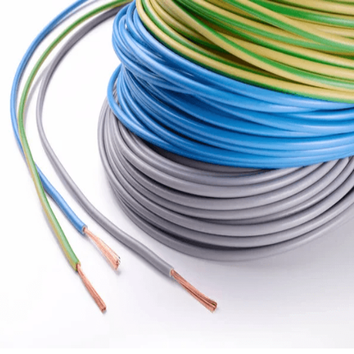
Some safety and efficiency checks should always be followed in electrical systems. Systems should be evaluated for wear, damage, or loose connections regularly to avoid hazards or inefficiencies. Only high-quality equipment and materials should be used, ones that are certified and compliant with accepted industry norms. Circuits should be properly labeled and never overloaded in any way. Before altering or repairing any installation, the power supply should be switched off, and proper grounding ensured to give protection against electric shock or fire. When there is any doubt, a professional electrician should be sought for guidance and must comply with the local electrical codes, such as the National Electrical Code, or NEC.
Recap of Key Points on Wire Size and Amperage
Choosing the right wire size is vital for electrical safety and efficiency. Wire size is essentially the amount of electric current it can safely carry without overheating. The AWG or American Wire Gauge system is generally used, with a small gauge number corresponding to thicker wire and greater current-carrying capacity. For example, a 12-gauge wire may be used to carry up to 20 amps, whereas a 14-gauge wire can safely carry up to 15 amps.
Factors may consist of the wire material (copper or aluminum), the circuit length, and the load. Copper wires tend to be preferred since they conduct better and wear well. A long circuit might need a thicker wire to combat voltage drops. Always check into the National Electrical Code (NEC) or local laws in terms of compliance with safety standards. Where there is confusion, a licensed electrician should be consulted.
Final Thoughts on Electrical Codes and Best Practices
When it comes to electrical codes and best practices, I always put safety first, along with adherence to the standards. I make sure to use copper wires because they are reliable, measure the circuit length to avoid voltage drops, and then go by the NEC or state bodies for compliance. Should I find myself overcome with doubts, I do not hesitate to hear from a professional electrician or an engineer in the field for his or her opinion. This way of going about it ensures the electrical installation is safe and efficient.
Remember
Electrical work can be dangerous and should only be performed by qualified individuals. Always consult with a licensed electrician for installations, repairs, or when in doubt about electrical safety. Following proper codes and safety procedures protects both people and property from electrical hazards.
Reference Sources
“Study of Electrical Systems in the Engineering Faculty of Udayana University, Bukit Jimbaran”
“Development of Vertical Axis Wind Turbine Charger as Alternative Power Source”
Frequently Asked Questions (FAQs)
What size wire is recommended for 60-amp circuits?
Under normal conditions, the wire sizes recommended for 60-amp circuits are 6 AWG copper and 4 AWG aluminum. Due to NEC guidelines being enforced at every electrical installation, this ensures the safety and efficiency of the installation. When determining wire size, the length of run and load on the wire should be taken into account.
How to calculate the voltage drop for 60 60-amp service?
The length of wire run, amperage, and gauge of the wire are the variables in voltage drop calculations for any 60-amp service. This formula interrelates the length of wire in feet, amperage, and the resistance of a specified gauge wire. Long wire runs exceeding 100 feet require that any voltage drop be minimized; this may necessitate an increase in wire size.
What different gauges of wire are employed for 60-amp service?
The commonly accepted wire sizes for 60 amp service are 6 AWG for copper and 4 AWG for aluminum. These wire sizes have the ampacity needed for a 60-amp circuit. You would change the wire size to ensure less voltage drop if the length of the run is considerable.
How does the NEC provide the rules for wire size selection?
The NEC provides guidelines for wire size selection, taking into account the current level, the type of wire, and the installation circumstances. For instance, for 60-amp circuits, the NEC recommends either number 6 AWG copper wire or number 4 AWG aluminum wire for safe operation. This way, the wire size will not be permitted to heat above its rated temperature and become unsafe; it also helps you to keep in line with your local electrical code.
What else should I look into before installing a 60-amp subpanel?
The subpanel wire size should be considered during installation; for example, 6 AWG copper or 4 AWG aluminum. The distance from the main panel should be considered, as longer runs require larger wire sizes to minimize voltage drop. Always check local electrical codes and consult a licensed electrician.
What differentiates a 60-amp service from a 100-amp service?
The difference between 60-amp and 100-amp service lies in their electrical capacity to handle loads. Because a 100-amp service can accommodate more circuits and handle higher demand from appliances than a 60-amp service, the wire size also varies, with a 100-amp service typically coming with 3 AWG copper and 1 AWG aluminum wire.
How are breaker sizes and wire sizes related?
Breaker size is directly related to the wire size, as the wire must carry the amperage the breaker is rated for. For example, a 60-amp breaker requires a wire of at least size 6 AWG copper or size 4 AWG aluminum to prevent overheating and ensure safe operation. If done correctly, your system will be protected from unnecessary tripping and damage.