The modern world of industrial and commercial undertakings, where dependability, safety, and performance come at a premium value, require efficient power distribution. Cable bus systems are one of the latest solutions that provide unmatched advantages compared to traditional wiring techniques. In this article, we will take a closer look at the unparalleled advantages of bus cable systems for power delivery relative to cost and meant enduring durability. In case you are looking to increase operational efficiency, improve compliance with industry benchmark standards, or both, this article makes a solid case about why cable bus systems are transforming electrical engineering and infrastructure.
What is a Cable Bus System and How Does it Work?
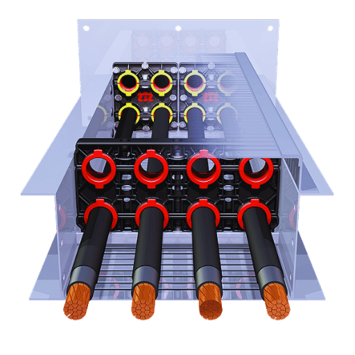
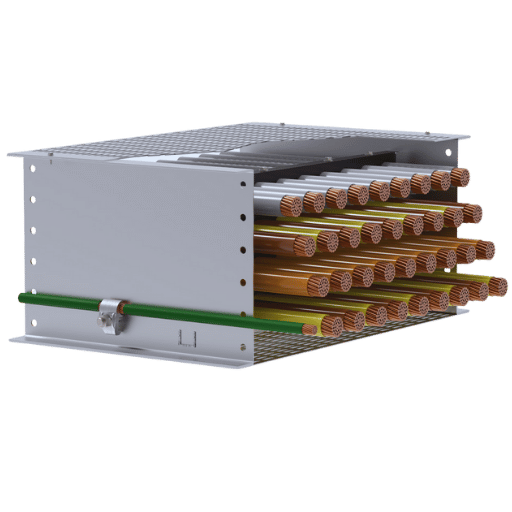
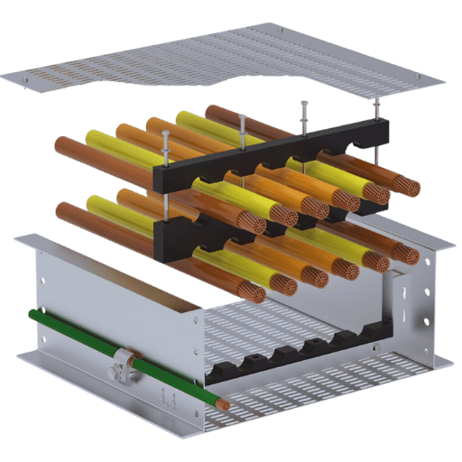
A cable bus system refers to an engineered power distribution system that enables the efficient transmission of electrical energy within short to medium distances. It comprises of power cables that are strategically arranged and mounted into a strong ventilated casing. This structure provides adequate shielding, reduces electrical leakage, and enhances cooling. Optimum power and voltage level parts are fabricated to precision, and the system as a whole is custom manufactured within the safety guidelines of the region. Due to their unmatched reliability, affordability, and effortless installation when aligned with traditional conduit systems, cable bus systems are predominant in industrial and commercial areas.
Understanding the Basics of Cable Bus
The four primary parts of a cable bus system are conductors, enclosures, supports, and terminations. Insulated current-carrying cables enclosed in a protective sheath are known as conductors. Enclosures shield overheating conductors from environmental hazards, provide protection, and ensure that no overheating occurs due to ventilation. Supports maintain alignment and minimize stress during operation. Terminations, which are the connection points of the cable bus system with electrical equipment, ensure the proper flow of current. All components work hand in hand to provide effective power distribution.
Key Components of Cable Bus Systems
Conductors
The screws in the bus system serves as the conductors enabling the flow of electricity throughout the cable bus system. These parts are usually made of highly conductive materials such as copper and aluminum because they have high current carrying capacity and low resistance. For example, copper conductors possess superior conductivity and work even better in high temperatures, unlike aluminum, which is more affordable and lighter but performs better on larger-scale tasks. Depending on the size of the system and its intended use, proper advanced conductor designs guarantee effective power delivery ranging from hundreds up to thousand amperes.
Insulation
Insulation aids in preventing short circuiting of wires, aids leakage currents, and ensures the electrical functioning of the system while maintaining safety measures. The more commonly used materials for conductor shields that provide high thermal stability along with moisture resistance and can withstand voltage ranges from 600 volts -76K volts (medium to high voltage applications) include crosslinked polyethylene (XLPE) and ethylene propylene rubber (EPR). The operating environment, current load, and the level of strength required determines the insulation material to use and its factors.
Enclosures
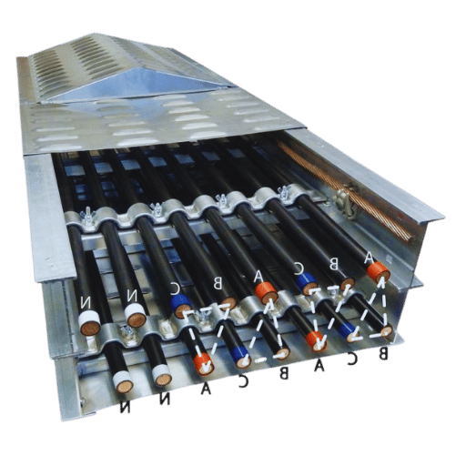
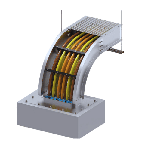
Internal components are sealed with a cable bus enclosure that keeps the internal parts safe from environmental damage such as water, dust, and physical impact. The enclosures are built out of strong plastics and metals, which further aid in thermal regulation with vents for air circulation. Most modern enclosures are known to incorporate particular standards set by a specific industry, such as Nema or IEC, which are built to withstand the follies of extreme weather and earthquakes while maintaining proper functionality.
Supports and spacers
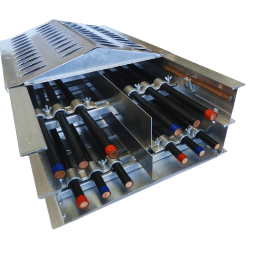
Supports and spacers carefully mount their conductors, which helps maintain certain distances to prevent short circuits and insulation damage that is caused by vibrations, moving stress, or heating. These elements are made from nonconductive and thermally resistant materials, which aid system reliability. The placement of supports at two to five-foot intervals is often mitigated to decrease sagging to better weight distribution in long cable runs.
Termination
As terminations define the interfacing boundary of a cable bus system with any electronic device, they serve as efficient and trouble-free connections to transformers, switchgear, and other devices. Termination kits that are never used above high voltage and current ratings will have to be produced, making use of advanced shielding that guarantees low impedance and heat dissipation. The proper installation of these parts will greatly increase the chances of maintaining an effective system for a long time.
Grounding System
Even though grounding refers to all parts of the electrical system together, in this case, grounding in capsule systems guarantees the safety of the equipment and the human using it. Grounding conductors, which are normally copper or aluminum in their raw form, are utilized to create a path with low resistance to the earth to ensure that electrical faults or surges do not do any harm. Guidelines for calculations rely on IEEE 80 so that they do not interfere with the fault of the overall system current projection and functionality.
The careful interconnection of these components at the same time in a coherent manner enables the cable bus systems to maintain durability, efficiency and add scale for power distribution in industrial commercial and utility applications. Each structure in a given project has to be planned accurately, putting in mind the major objectives of controlling performance, costs, compliance to safety regulations, and optimizations.
The Role of Insulated Conductors in Cable Buses
Insulated conductors comprise an essential part of cable bus systems that require proper power engineering for safe and reliable power transmission. Usually high quality copper or aluminum is used in the construction of these conductors alongside a heavy insulation which defends against electrical leakage, corrosion, and short circuiting. The insulation material utilized is specially formulated for operating conditions such as resistance to temperature, dielectric strength, and fire.
Modern industry standards such as IEEE, IEC, and ANSI are now incorporated in insulated conductors with an emphasis on safety and dependability under harsh conditions. For example, cross-linked polyethylene (XLPE) and ethylene-propylene rubber (EPR) insulating materials are popular due to their impressive thermal and electrical insulating properties. These materials can withstand high temperatures of 90°C and even higher for short bursts of overloads, making them useful in industrial and utility applications.
Research shows the importance of conductor sizing in reducing energy losses alongside efficient distribution of power. With this in mind, oversize conductors do improve system efficiency due to reduced resistance, however, the cost constraints alongside physical space in the cable bus make it impractical. Furthermore, the recent improvements in manufacturing techniques have led to enhanced flexible conductors, which greatly reduce the mechanical stress on components during installation.
Insulated conductors within cable buses contribute to system adaptability, strength, and operational safety by working alongside specific engineering and compliance standards. They are vital to the overall functionality of the power distribution system infrastructure.
How Does the Installation of a Cable Bus Differ from Other Systems?
Steps for Successful Cable Bus Installation
Assessment and Planning
Conduct a preliminary site analysis for assessing spatial requirements and determining available technologies that can be implemented. Construct a comprehensive installation strategy paying attention to system arrangement and other relevant considerations.
Setting up the Foundation
Ascertain the mounting location for the cable bus in question. Bases must be leveled and constrained for immobility to ensure balance under the system’s weight over protracted periods.
Structural Support
Set up relevant support structures like brackets or trays that will properly secure the cable bus. Cross-check that the supports have been verified from a structural engineering perspective concerning design alignment and bearing capacity.
Placement of the Cables
Position the conductors within the cable bus housing under the required standards. Electromagnetic interference, alongside other factors, renders spacing imperative alongside optimum freeness to maximize airflow.
Assembly of the Housing
Non-environmental factors like moisture and other forms of debris make proper sealing imperative which renders assembling the protective casing for the cable bus equally important.
Completing the Connections and Terminations
Perform all required connections alongside the terminations for both ends of the system. Relevant guidelines alongside standards provide the criteria upon which relevance to the connections will be determined.
Final Testing and Inspection
Put the installed system through checks like continuity alongside putting the insulation resistance and load test under scrutiny. Go over the entire installation to affirm its validity tracing back to the design that has been laid out alongside the safety measures that have been incorporated.
Last Modifications
Carry out any changes required from the testing to ensure the system runs as designed before project handover. Record how the setup was completed and how to maintain it later on.
Comparing Bus Duct and Cable Bus Installations
In my view, the difference between bus duct and cable bus installations is best evaluated in the context of a specific project scope. For instance, bus ducts are usually chosen for systems that have high current carrying requirements, are easy to expand, and have a compact design. They also perform well with decreasing vertical space and environments characterized by short, straight runs. Alternatively, cable bus systems are more economical for construction layouts with lower current requirements because they are easier to modify. Regardless, all options present unique advantages that must be analyzed against criteria like system capacity, system design, cost, and future growth potential.
Why Choose MP Husky Cable Bus Systems?
Benefits of Using MP Husky for Your Electrical System
MP Husky Cable Bus Systems offer various competitive benefits for electrical system applications. These systems are specially crafted for improved operational efficiency, containing low maintenance requirements and sustained reliability. Their modular construction makes installation and adaption fast and simple, which is ideal for new buildings and upgrades. Furthermore, MP Husky Cable Bus Systems are excellent at cost-effectiveness by minimizing material and labor costs while maximizing performance. Due to their durable design, industry standard compliance, and system safeguards, MP Husky Cable Systems are reliable even under harsh conditions.
Understanding CSA Standards in Cable Bus Systems
The Canadian Standards Association (CSA) has created standards for the safety, dependability, and efficiency of operating various electrical systems which include cable bus installations. With regards to cable bus systems, CSA Standard C22.2 No. 273 alongside other documents stipulates important prerequisites pertaining to design, testing, and installation within safey industry constraints and operational goals.
They additionally perform thermal rise tests to confirm that the cable and bus arrangements function properly under presumed load conditions. About CSA Standards, these boundaries guarantee that systems endure considerable electric currents without any risk of degrading insulation or developing electrical faults. CSA standards for cable bus systems hold these primary principles to be self-evident.
The CSA standards also emphasize prerequisites like durability for conductors and their protective armor. This would make certain that serviceable life spans are achieved even when placed in harsh conditions. Policy guides also outline requirements for maintenance free reliable service in enduring environmental situations.
Theses rules set by CSA have vertical and horizontal spacing limits and clearance values which eliminate arcing and short circuits. Furthermore, typical CSA policies demand that system designs fulfill correct phasing and grounding for effective tamper-proof shielding.
Compliance with CSA standards increases safety of the system while optimizing the operating procedures of local agencies, thus shortening the time to complete the project. It is also easier to safeguard people and equipment from possible dangers using industry-grade reliability. Therefore, companies installing CSA certified cable bus systems can be confident their installations are built to channel industry-grade reliability.
What Are the Voltage and Ampacity Considerations in Cable Buses?
Managing Voltage Drop in Cable Bus Systems
In designing and operating cable bus systems, voltage drop is one of the most important parts to consider from an engineering perspective. Too much voltage drop can lead to weak efficiency and performance. Voltage drop is caused by the ohmic resistance and impedance of the conductors, losing some voltage due to the passage of electric current. Tactical steps must be taken to ensure that voltage drop is minimal so that there is dependability in power delivery and there is compliance with electrical codes.
According to the National Electrical Code (NEC), a single run of feeders and branch circuits should not exceed 3%, and for the total of the entire circuit, there is an upper limit of 5%. The same principles apply to cable bus systems, but they also include the following variables: the material of the conductor, the area of the cross-section, the length of the conductor, and the amount of current that is loaded. The resistivity of copper is lower than that of aluminum, so copper is a common conductor material used especially for systems with high demand. For example, 400 amps through a copper conductor of 500 MCM for 500 feet causes a voltage drop of around 3%, which is much lower than that of aluminum.
To avoid the voltage drop problem in overhead power lines, conductors are oversized, or a parallel cable arrangement is used. It is often the case that an increase in the size of the conductor results in lower resistance. In the case of parallel cables, the distribution of current among the conductors is better, which reduces the overall resistance effect. Also, strong, non-corrosive, and low resistant connections at the termination points of the conductors have been shown to protect against localized resistive losses.
In addition to the considerations above, when developing a cable bus system, the operating voltage and phase configuration (single-phase or three-phase) are also important. Three-phase systems appear to have a lower voltage drop in comparison to single-phase due to better load balancing, which is an added advantage for long cable runs. Generally, engineers use software tools and modern models to calculate and optimize the cable size, the routing of the cable and ensure that the drop in voltage achieved is within acceptable limits without compromising system efficiency, system compliance, or regulatory standards.
With the approaches above, along with precise and accurate calculations of voltage drop, the bus systems will offer optimized power usability without any energy wastage while retaining peak performance throughout their lifespan.
Calculating Ampacity for Efficient Power Distribution Systems
Ampacity is defined as the safe maximum level of current that can be carried by a conductor without exceeding its set temperature limit. Three important factors need to be evaluated in the calculation of ampacity:
- Conductor Material: Usually, aluminum and copper are the dominant materials. Copper is more common because its conductivity is better than aluminum and, therefore, has a higher ampacity.
- Ambient Temperature: The surrounding temperature has a direct impact on how well a conductor can dissipate heat. Adjust the calculations from the defined ampacity range according to the installation geography.
- Cable Configuration: Parameters such as cable bundling, type of insulation, and installation technique affect the thermal dissipation as well as the ampacity.
In perhaps the most thorough code of electrical practice, the National Electrical Code (NEC), as well as other local regulations, include tables for ampacity, as these are necessary for safe operation and to simplify the calculations. For best practice and system stability, always follow these recommendations.
How Does System Design Affect the Performance of a Cable Bus?
Designing for System Balance and Efficiency
The balance and efficiency of a cable bus system design are very important constraints that influence its operational effectiveness, dependability, and safety. Balance optimization begins with a meticulous load analysis, or else current divisive imbalance leads to uneven currents among conductors. The cables in the system will not work efficiently as residual imbalance causes load overheating, thereby diminishing system health and efficiency. Advanced cable configuration tools and modeling software are necessary for simulation so that optimizations and thorough analyses of balance imbalance configurations can be performed.
Power loss, which is a measurement of efficiency for any system, is usually caused by system conductors’ resistive characteristics. With copper conductors, resistive losses can greatly improve using copper with better conductivity (ex. 101 IACS for annealed copper wires). Furthermore, studies show that switching over from conventional aluminum conductors to high-grade copper ones leads to a nearly 40% reduction of power loss depending on the set operational demands.
The thermal management performance of EMI is shaped by spacing and installation techniques. Adequate spacing of conductors, as researched directly, reduces operational temperatures, leading to an increase in heat dissipation efficiency while ensuring the integrity of the conductor. Other studies have shown that increasing conductor spacing in highly loaded systems leads to remarkable temperature drops of around 15-20% in improvement under intensive operational loads.
Lastly, balancing effectiveness and refining cable bus design requires sophisticated software, premium materials, and compliance with electrical codes. If engineers pay attention to these aspects, they can achieve reliable and enduring system performance.
The Impact of Ventilated Enclosures on Cable Bus Performance
Cable bus systems are highly affected by the use of ventilated enclosures as they directly impact the life and efficiency of the equipment due to heat and thermal performance factors. With the use of these enclosures, the airflow around the cables is improved, which in turn helps dissipate the heat produced by the current and the environment. Research indicates that the proper levels of ventilation in enclosures can reduce the operating temperatures of the cables by 10-15%, which reduces the chances of thermal damage occurring to the insulation materials and enhances the durability of the system as a whole.
Current industry surveys underscore that effective control of airflow in ventilated enclosures also aids in lowering resistive losses. Decreased operating temperatures lead to increased resistance within the conductors, therefore, lowering energy and expenses in the long run. In terms of large scale operations, this results in a significant reduction in power loss which is beneficial for business during peak load times.
To optimally harness the advantages of ventilated enclosures, modern designs include placed louvers, perforations, or mesh elements to enhance natural convection or forced airflow. Also, adherence to primary standards such as IEEE and NEC ensures that enclosures are built to overheating risks and structural environmental boundaries. As a result, these sophisticated design features provide a sustainable solution to the escalated energy requirements of industrial and commercial undertakings.
Incorporating Parallel Conductors in Your Cable Bus Design
Achieving the desired level of performance and reliability within the system when adding parallel conductors to cable bus design is fundamental. In the fore section, there should be a proper allocation in the mark off cut length of conductor from its material to its size so as to achieve a homogenous current distribution along the length of the conductor. Any disparities may expose the conductors to overheating or unbalanced loads. Moreover, adequate spacing and firm supports limit electromagnetic effects and reduce conductor stress.
Verification of compliance to pertinent requirements is very important, for example, with the National Electric Code (NEC). These set restrictions provide useful information concerning the ampacity limitations, spacing, and positioning of conductors about other elements of the system. Thermal modeling or even experienced engineers may greatly assist in improving guidelines on installations. A uniform and exact approach serves the purpose of safe and durable operational life of the cable bus system.
What Role Does Fitting Play in the Efficiency of a Cable Bus System?
Choosing the Right Fitting for Your Feeder System
Selecting the correct fitting for your feeder system is critical to making sure there is safety, performance, and reliability. Safety fittings prevent streams of fluids from escaping the system and ensure that components are properly connected and aligned. Dust, moisture, and temperature variations can pose a threat to the system, and fitting them can provide protection. The material of the fitting, the associated system voltage, and environmental factors where the fitting would be installed must be ensured. Using appropriate fittings can lower the chances of an outfitting failure due to sub-standard quality. Following specifications and manufacturer guidelines is crucial in attaining the desired outcome.
The Importance of Cable Support and Insulation
Correct cable support and insulation are critical to operational effectiveness and safety within an electrical system. Cable support systems such as trays, ladders, and conduits properly place cables within a structure. Also, these systems prevent mechanical strains or stresses that could pose damage over time. In the absence of sufficient support, cables are prone to sagging due to hydrodynamic forces, being subjected to external forces, and pressure, vibrations, or shocks, all of which can cause faults and premature failure of the system or parts.
The balance between risks of shocks and leakage is maintained by insulation, thus further strengthening the system and reducing the possibility of short circuits leading to the failure of critical components. Insulation is also subjected to other environmental forces such as moisture and heat, which, alongside chemicals, lower the quality and value of the system by its unplanned use while increasing the reliability of the entire setup. Both cable support and insulation work towards diminishing the risk of hazards or degradation, strengthening the installation’s safety and durability. Best practices and industry standards boost the reliability for cable management within the system and framework, enhancing the performance and aiding in reduced expenditure for maintenance in the future.
Frequently Asked Questions (FAQs)
Q: What do Superior Cable Bus Systems provide over a traditional conduit system?
A: With Superior Cable Bus Systems, there is an increase in free air circulation, which leads to better impedance and space utilization. Moreover, they provide more flexibility in installation and better handle short circuit conditions than traditional conduit systems.
Q: What distinguishes MDF Cable Bus Systems from other methods of power distribution?
A: Unlike other methods of distributing power, MDF Cable Bus Systems are specifically tailored for optimal power distribution. They offer improved ampacities and are preferred over bus duct systems or cable tray setups due to their safe and efficient design.
Q: What function does cable insulation have in the context of Superior Cable Bus Systems?
A: In the case of Superior Cable Bus Systems, cable insulation is vital to provide safety against short-circuiting but also to maintain the distribution of electricity. Moreover, it helps the system withstand high ampacities.
Q: Why is the concept of ‘free air’ significant to the design of cable bus systems?
A: Free air or “open air” provides cooling of the cables; therefore, the ampacity of the cables is rated higher, and the cable is less likely to overheat. This is one of the primary benefits of Superior Cable Bus Systems in comparison to cable in tray or conduit and wire systems.
Q: Is it true that Superiorbus Cable Bus Systems can be used for both indoor and outdoor installations?
A: Indeed, Superiorbus Cable Bus Systems are built to be flexible with both indoor and outdoor installations. They are designed to withstand different environmental conditions and still maintain proper power distribution.
Q: In what way does a Superior Bus System prevent cable movement during operation?
A: A Superior Bus System employs specific cable blocks and rungs that effectively mitigate cable oscillation. This ensures steady and dependable performance of the power distribution system.
Q: What makes the Superiorbus Cable Bus System the best choice on the market?
A: The Superiorbus Cable Bus System stands out from its competitors due to its unparalleled effectiveness, safety, and adaptability. It is carefully tailored for high ampacities, low space requirements, and exceptional short-circuit handling, making it the preferred choice for engineers and purchasers of MP Husky Cable.
Q: Does Superior provide any Cable Bus Systems installation manuals?
A: Yes, installation guides are offered for each separate model of Superior Cable Bus Systems. These manuals are intended for engineers who need to adequately operate the systems after successful installation.
Q: In what ways do Superior Cable Bus Systems help with lowering system impedance?
A: The use of insulated power cables and the arrangement of the cables within the bus housing lead to reduced system impedance, which enhances the overall performance and reliability of the system.
Q: Can any additional cables be connected to a pre-existing Superior Bus System?
A: Yes. Additional cables can be integrated into an existing system with ease. The design of the system permits upgrades without requiring major changes to the configuration of the system while still retaining the original power distribution network topology.
Reference Sources
1. Superconducting Bus-Bar with Nuclotron-Type Cable: A Study on Its Thermal Behavior
- Authors: Ł. Tomków et al.
- Published: April 3, 2023
- Journal: Archives of Electrical Engineering
Key Findings:
- The work evaluated the thermal behavior of a superconducting bus bar in the SIS100 particle accelerator using numerical methods.
- It also analyzes the heat produced due to the rapid changes in current within the Nuclotron-type superconducting cables.
- It was found that the hysteresis loss in the cable is low in comparison to the heat loss in the superconducting magnets which means that the current carrying capacity of the cable is large.
Methodology:
- The results were based on the nominal geometric dimensions of the bus system and the particular insulation used, with the environment’s heat transfer and hysteresis loss components being the focus of the computation (Tomków et al., 2023).
2. Distributed Time-Domain Reflectometry Techniques for Multiple Faults Detection and Location in Bus-Shaped Cable Networks
- Authors: Dhia Haddad et al.
- Journal: IEEE Sensors Letters
- Published: May 1, 2022
Key Findings:
- The authors presented a problem of detecting and locating multiple faults in cable networks, which is done using distributed time-domain reflectometry (TDR).
- The argu- ments stated in the paper cover the distinctiveness of TDR in fault detection which is important in cable network maintenance.
Methodology:
- The authors analyzed the response of cable networks to fault conditions using distributed TDR techniques, which provide a great approach to systematic structure fault detection (Haddad et al., 2022, pp. 1-4).
3. Recognition of Aircraft ARINC Bus Cable Faults Using SSTDR Techniques
- Author: Xudong Shi et al.
- Published: June 1, 2021
- Journal: IEEE Systems Journal
Key Findings:
- This paper proposes the methodology of inline fault detection on ARINC bus cables and SSTDR.
- This technique improves the reliability of fault detection by reducing the interference of the bus signal with the incident signal.
Methodology:
- The authors of this study developed an SSTDR-based online detection model through analysis of ARINC bus cable impedance and reflection characteristics(Shi et al., 2021, pp. 2482–2491).