The process of wiring a 3-way light switch can appear intimidating for someone who is not familiar with electrical systems. However, this is a skill that, once mastered, changes when it comes to controlling lights around the house, so much-wanted functionality and convenience. The guide will try to make it accessible by breaking it down step-by-step for beginners and will even be handy for experienced DIYers. By the end of this article, you will understand what tools and materials are needed, a basic wiring diagram, and the steps used to wire a 3-way switch are essential. Consider this your all-in-one resource for ensuring you do right on the first attempt while upgrading your lighting or working on a home project.
Understanding the Basics of a 3-Way Switch
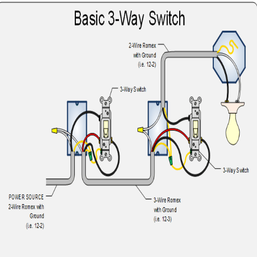
The lighting can be turned on and off from two locations through a 3-way switch. Ordinarily, a 3-way switch system finds itself in hallways, staircases, or large areas where it is convenient to have multiple control points. It gets connected to two switches using traveler wires through which the flow of electricity can be interrupted or completed from either switch. One has to understand the interaction of wires-hot, neutral, traveler, and ground-for proper installation.
What is a 3-Way Switch?
A three-way switch is a type of electrical switch that allows you to operate a single fixture from two different locations. This kind is used mostly for staircases, for long hallways, or large rooms. In the three-way arrangement, two three-way switches are used with traveler wires connecting them. Each switch interacts with the traveler wires to either open or close the circuit started by the other switch.
3-way switches have a very straightforward operation. Each switch has 3 terminals, with one terminal called a common terminal and two others known as traveler terminals. The common terminal connects either to the power supply or to the fixture, while the traveler terminals are connected with traveler wires. This way, the current passes down one wire or the other, depending on the positions of each switch.
When installed correctly, it informs that walking across a space to turn lights off or on is unnecessary-the enhanced convenience benefits are likewise energy efficiency. Hence, at all times, it is wise to have at least fundamental knowledge of wiring, to follow the electrical codes during installation, and to make sure power is shut off.
How 3-Way Switches Work
With a 3-way switch, two switches are used to operate one light fixture or option set of lights from two different points. This is achieved via wiring compatible with three terminals on each switch unusual consideration that most would liken to an “exotic” wiring configuration. One terminal is called “common,” with the other two-“traveler” terminals. The operation of the switch depended upon the conduction of electric flow through these terminals. Once one switch is operated, the electrical path changes, which switches the light either on or off.
The thing that makes the 3-way switch tick is its wiring. A 3-conductor cable, usually black, red, and white plus ground, runs between the two switches. One switch’s common terminal is attached to the power source, while the other’s is attached to the light fixture. The traveler terminals are wired to each other, thus running two parallel electrical paths with which a user can toggle the circuit (open or closed) by flipping either switch; it doesn’t matter what position the other switch is in.
Components of 3-Way Switch Wiring
The 3-way switch wiring system consists of a series of working parts that control one light from two locations. Below is a detailed overview of the critical components and their functions:
These switches are unique in that they offer three terminals. Two terminals, commonly called “traveler” terminals, carry current between the two switches; hence, this terminal is the common terminal connected to either the power source or the light fixture. Some newer types of switches have a separate terminal for ground.
These wires connect the two switches. Bear in mind, these wires are usually color-coded, probably red and black. They pass current between the switches so the circuit can be completed, no matter the position of either switch.
The earth wire is essentially a safety wire. It stops electrical hazards by diverting any excess current, in the event of a fault, into the earth.
The circuit starts from the power source that provides the potential difference required for the operation of the system. This is mostly a 120V or 240V AC power supply to the residential consumer, depending upon the local standards.
The light is the circuit’s terminal load and is connected to the system using load wires. Depending on the flow of electricity in the load wires, the light will either glow or remain off; this flow is controlled by the switches.
The neutral wire returns the current back from the load terminal to the source and completes the circuit. This wire ensures that the current is properly distributed through the wiring.
These are enclosures for the connections of different wires, preventing physical damage and also reducing the risk of fire due to loose connections. Usually installed at the switch locations and at the light fixture.
When one learns what each element does in the wiring system, they can go a long way toward understanding how a 3-way switch gets its job done. With the modern advances in circuit design, safety, and efficiency have been kept in mind, and these systems can be installed for both traditional and smart home applications.
Tools and Materials Needed to Wire a 3-Way Switch
Complete Materials List
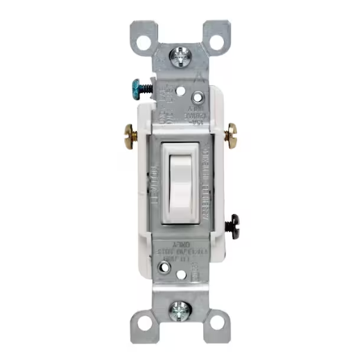
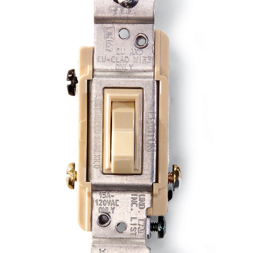
- 3-Way Switches: A pair of switches with two-way operation. It allows for switching one light or fixture from two separate locations.
- Electrical Wire: 14/3 or 12/3 gauge, depending on the specification of the circuit, with a ground wire.
- Wire Connectors: Twist-on connectors for making wire connections.
- Screwdriver: Both flathead and Phillips are required.
- Wire Strippers: For removing insulation.
- Voltage Tester: To ensure that the power is off before working.
- Electrical Tape: To provide extra insulation on the wire connectors.
- Wall Plate Covers: To put it all together and cover up the switches.
Important: Ensure that all tools and materials adhere to the electrical code and safety standards before beginning the installation process.
Essential Tools for Wiring
On any project, having the right tool means safety, efficiency, and accuracy combined. Here’s a complete listing of tools for wiring tasks:
| Tool | Purpose | Key Features |
|---|---|---|
| Screwdrivers (Flathead and Phillips) | Drive and unset screws | Insulated handles for protection, magnetic-tipped options prevent hardware from falling |
| Wire Stripper-Cutter | Strip insulation and cut wires | Multiple notches for different wire gauges, integrated cutting blades |
| Voltage Tester | Check for live electrical circuits | Non-contact testers are most popular for safety, no direct wire contact needed |
| Multimeter | Measure voltage, current, and resistance | Digital multimeters offer highest accuracy, continuity testing functions |
| Electrical Tape | Insulate exposed wires and connections | Heat-resistant, voltage-rated for specific applications |
| Pliers (Needle-Nose and Linesman) | Wire manipulation and cutting | Needle-nose for tight spaces, linesman for heavy-duty cutting and twisting |
| Cable Staples and Staple Gun | Secure wires to surfaces | Organized wire routing, secure mounting to walls or baseboards |
| Wall Plate Covers | Finish installation appearance | Match colors and materials to complement room aesthetics |
Ensuring each tool performs its particular function will help work efficiently and reliably. Buying top-grade tools that meet safety standards will not only reduce unnecessary risks but also increase the life and success of your electrical installations.
Safety Equipment to Consider
While working with any electrical system, safety must be prioritized. Here is the recommended safety equipment to keep in mind:
- Insulated Gloves: Protection from electrical shocks while working with bare wires or components.
- Safety Glasses: Protect your eyes against potential sparks or floating debris encountered during installation or inspections.
- Rubber-Soled Shoes: Prevent a path to electrical grounding and provide traction on slick surfaces.
- Non-Conductive Tools: Always use tools in which handles have been insulated against electrical contact.
- Circuit Breaker Lockout Devices: Preclude accidental energization of the circuits during work.
- First Aid Kit: This should be close at hand for emergencies, which may include burns or minor injuries.
Equipping yourself with these safeguards will protect your health and ensure you abide by the best practices in electrical safety. Always inspect your equipment before commencing any work.
Step-by-Step Guide to Wiring a 3-Way Light Switch

Complete Installation Process
Switch Off the Power
Before working on the installation setup, turn off the power to the circuit you’ll be working on at the main breaker panel. Check with the voltage tester to be absolutely sure the switches are de-energized.
Get the Wiring Components
Understand the key components that go into a 3-way light switch wiring. They will include two 3-way switches, traveler wires, a ground wire, and the light fixture.
Connect the First Switch
Find your first switch box and go ahead and connect the ground wire to the green screw on the switch. Connect the common wire (usually black) to the common terminal screw and the traveler wires (usually red and black) to the traveler terminals.
Wire the Light Fixture
Run the traveler wires and the common wire to the light fixture. Connect the ground wire to the grounding screw on the fixture and the common wire to the light’s terminal. Be sure all connections are secure.
Connect the Second Switch
At the second switch box, connect the traveler wires accordingly to the traveler terminals. Connect the common wire to the common terminal screw and the ground wire to the green screw.
Test Your Work
Test the installation after turning on the power. Check that the light works correctly when either switch is flipped.
By following these instructions, a 3-way light switch will be safely and properly installed. Always observe the code, and if in doubt, consult an expert.
Preparing Your Work Area
Turning off a power source is a precautionary measure to ensure safety and efficiency while working with electrical components. It should be followed by the use of a reliable voltage tester to verify the absence of current in the circuit. Another important factor is clearing and organizing the workspace. It should be well-lit and free of anything that might cause accidents or misplacement of tools.
Inside a house, keep the place dry since wetness is a serious electric hazard. Gather tools such as wire strippers, pliers, and screwdrivers in advance and ensure that they are insulated for electrical work. This amount of time is enough to meticulously install the device without routing any faults.
Be careful with old wiring or exposed materials. Sometimes, outdated systems include materials hazardous to health, such as lead or asbestos in the wrapping. Adhering to the updated local electrical code is obligatory in order to uphold safety standards and to avoid fines. Now that you are carefully prepared, your project is ready to start on a correct and safe footing.
Identifying Existing 3-Way Switch Wiring
The main goal here is to acknowledge and identify the wiring setup for a 3-way switch to ensure its installation and troubleshooting. Controlling a single light fixture from two different locations is common in staircases, large rooms, or hallways.
A 3-way switch wiring setup consists primarily of two switches and one light fixture interconnected by various wires. Usually, the wiring is as follows:
- Line/Hot Wire (black copper): This wire brings power from the panel to the switch.
- Traveler Wires (Black and Red): These wires connect the first switch to the second one, allowing control from both locations.
- Common Wire (Black): The common wire on one terminal of one switch is either power to the light fixture or power from the source; the common on the other switch is usually the traveler coming to or from the light fixture.
- Neutral Wire (White): Completes the circuit by providing the return path from the panel to the light fixture.
- Ground Wire (Green or Bare Copper): Used as a safety grounding to avoid electrical accidents.
In confirmation of the existing wires in your installation, check carefully the arrangement of wires inside the electrical boxes of both switches. Use the voltage tester to confirm which wires are hot, travelers, and neutrals. This should only be done after switching off the power from the breaker to avoid any accidents.
Note that wiring setups may vary with the house’s age and the electrical standards of the location; for example, an older installation may not have had a ground wire or a neutral wire, which modern safety codes require. So refer always to the most up-to-date diagram and guide relevant to your state’s electrical code to find something similar to yours.
Wiring the 3-Way Switch: Step-by-Step Instructions
Detailed Wiring Process
Turn Off Power
First, ensure that the power to the circuit is turned off at the breaker box. Use a voltage tester to make sure no electricity is flowing.
Understand the Terminology
A 3-way switch circuit simply means two switches control one light or set of lights. The key components of concern are traveler wires, a common (or hot) terminal, and a ground wire. Make sure you’re clear on this layout before beginning.
Connect the Ground Wires
Connect the bare or green ground wire to the green screw on each switch, and then attach the other end of the wire to the fixture. If the ground wires are not already coupled together inside the electrical box, use a wire nut to connect them with pigtails going to each switch.
Attach the Common Wires
Look for the “common” terminal on each switch; it is usually a darker colored screw, or it might be labeled as “common.” Connect the wire coming from the power source to the common terminal on one switch, and connect the wire that goes to the light fixture to the common terminal on the second switch.
Install the Traveler Wires
Traveler wires (generally red and black) carry current between both switches. Connect the traveler wires to the two lighter-colored screws (traveler terminals) on each switch. Make sure that what you connect on one side is also connected on the other side.
Wiring the Light Fixture
Connect the black wire of the light to the wire coming from the common terminal of switch 2. And connect the white wire of the light to the neutral wire coming from the power source. Use wire nuts to secure the connections.
Double-Checking the Connections
Look closely at all connections and see to it that they are tight and correspond to the wiring scheme. Loose or incorrect wiring can lead to faulty operation and safety problems.
Mount the Switches and Light Fixture
Fold in the wires into the electrical boxes and install the switches. Mount the light fixture to its housing per the manufacturer’s instructions.
Restore Power and Test
Energize the circuit back at the breaker panel. Test both switches to ascertain that each works independently in turning the fixture on or off.
By performing these tasks, a 3-way switch circuit can be wired safely and effectively. Should any unfamiliar instances arise, refer to local codes or hire an electrician.
Troubleshooting Common 3-Way Switch Wiring Issues
Common Problems and Solutions
If the problems persist even after you realize the problems and/or rectify them, then hire a professional electrician to take care of it for a safe resolution.
Identifying Wiring Errors
Tackling wiring errors in light switches must be done with accuracy, safety, and functionality. Improper connections, mismatched wire types, or simply aging electrical components form the most common wiring issues.
One primary item to check is the alignment of color wires-black meaning hot; white, neutral; whereas green or bare copper wire represents a ground wire. Badly swapped hot and neutral wires at terminals may cause circuit discontinuity and give rise to hazards. Another common instance is wire mislabeling during installations in an older house where non-standard color coding is in use.
Inspection tools, like a voltage tester or multimeter, will point clearly to the type of fault. For instance, measuring an abnormally high voltage between the neutral and grounding wires indicates a loose connection or a broken neutral wire somewhere along the circuit. Loose screws in switch or receptacle terminals can cause lighting problems with intermittent operation or flickering.
Junction boxes must be thoroughly inspected because a congested or poorly spliced wire can strain a given system. Furthermore, it must be confirmed that the wiring conforms to the latest code in the National Electrical Code (NEC). The NEC changes these requirements periodically to promote electrical safety, and operating in violation of the code increases the inherent hazards of the operation itself.
For DIY, knowing the layout of the circuit and creating a detailed wiring map is helpful to avoid any oversights. When in doubt or faced with confusion, it is better to consult a certified electrician to maintain system integrity. Proper diagnostics would avoid any issues down the line and provide peace of mind to homeowners.
Fixing Common Problems with 3-Way Switches
Certain usual problems with 3-way switches will require some knowledge of their functionality and common faults thereof. A 3-way switch operates a light fixture from two different locations, usually by means of two switches that share the control; errors might, however, occur from improper wiring, a loose connection, or a faulty component.
One of the common problems is improper wiring of the traveler wires-the wires that run from one switch to the other. This can lead to erratic behavior, such as lights that only turn on and off from one switch. Fixing this problem requires that the traveler wires be traced and verified. It helps to use a multimeter to test for continuity in order to discover which wires were mislabeled or incorrectly installed.
More commonly related to the loose lots would be loose wire connections at the terminals. There may be the loosening of screws, the wires becoming detached, and the wires having been fastened improperly due to vibrations, wear, or simply bad installation. Properly tightening the terminal screws and ensuring that all wires are properly connected solves this problem. Also, look for signs of corrosion or damage, especially in older systems. You can guarantee reliability and safety by repairing any damaged wires or switches with good-quality components.
Bad or failing switches might be another candidate, as internal wear or mechanical failure might prevent a switch from functioning correctly. The answer to this problem is to replace the faulty switches with those contemporary and dependable ones designed for 3-way operation. They should be present from a safety perspective; consequently, they would last longer and lessen any chance of an electric hazard.
If the lights flicker or buzz, you might be dealing with some resistance or a bad connection in the circuit. So you might want to consider replacing the old switches or checking the manufacturer’s wiring guide for reference. For durability, consider those switches rated for any amp in the particular circuit.
Understanding a 3-way switch circuit diagram can make inspection much easier, especially when cross-referencing the map during repairs. Wires should be labeled when installing or in the repair process to avoid recurring issues. Anyone who is not confident about dissecting the wiring layouts should consult an electrician so that diagnostics can be accurate and repairs will be safe.
When to Call a Professional Electrician
Professional Help is Needed When:
There are certain situations in which it is safest and most reliable just to call a professional electrician. For example, frequent tripping of circuit breakers or flickering lights could mean an overloaded or faulty electrical system of sorts.
- Major electrical upgrades: Replacing service panels or rewiring portions of the home
- Complex installations: Projects requiring permits or code compliance verification
- Safety concerns: Burning smells, buzzing sounds, or scorch marks on outlets
- Older home inspections: Worn-out wiring systems like knob-and-tube or aluminum wiring
- Overheating or short circuits: Signs that may quickly turn into life-threatening situations
The major electrical upgrades, such as replacing the service panel or rewiring a portion of the home, require the skills of a licensed electrician. These undertakings are not only complicated in terms of trade but must also adhere to the local electrical codes and safety standards. Even seemingly simple projects, such as installing a new receptacle or patching a damaged wire, can become quite dangerous if not done properly. Electric shock and fire hazards are the foremost concerns.
In terms of the older home, render inspections should be scheduled regularly. The worn-out wiring setup, such as knob-and-tube or aluminum wiring, of an older house may pose risks to cope with the heavy energy demand. Data reveal that the actual installation of new wiring and grounded outlets enables maximum energy efficiency, followed by safety.
A professional electrician is engaged so that homeowners can be assured of work being done with utmost safety and consideration, thus giving them security and saving money in the long run against repairs or installations done improperly. Whenever there arises a need for such work, give precedence to professionals to protect your property as well as its occupants.
Mastering Your 3-Way Switch Wiring Skills
Summary of Key Points
- Power Off and Test Wires: Always turn off the power at the main breaker before starting any electrical work. Use a meter to ensure that there is no voltage to maintain safety.
- Recognize Switch Terminals: Identify the common terminal, the traveler terminals, and the ground wire at the switches. This must be done without fault to properly wire a multi-way switch.
- Follow a Wiring Diagram: Refer to a wiring diagram that matches your configuration to ensure that you correctly connect terminals and wires, steering clear of common errors.
- Use the Right Tools: Use quality tools such as insulated screwdrivers and wire strippers that will ensure the convenience and safety of your work.
- Get Help When Needed: If uncertainly grips you or if the wiring is intricate, consider calling an electrician so the work can be done accurately and safely.
Mastering the 3-way switch can be difficult unless you have a grasp of the basics. These switches allow one light or set of lights to be controlled from two different locations-much useful for use in hallways, staircases, or very large rooms. Wires called traveler wires, the common terminal, and a ground wire will be one’s major considerations. Always start by determining these wire connections on your 3-way switches, and never work on any wires unless the circuit breaker has been switched off. Use a multimeter to check for any that might still be live, applying a wiring diagram methodically. If you follow these steps, the installation or repair will be safe and hassle-free and will undoubtedly boost your confidence in such undertakings in the future. When in doubt or when assistance is necessary, always consult a professional electrician.
Encouragement for DIY Projects
DIY projects are immensely satisfying and empowering to me. What I’ve discovered is that with careful planning, the right tools, and the right attitude to learn, even the more complicated ones can be done. When a challenge arises, it presents a wonderful opportunity for me to enhance my skills and develop better problem-solving abilities. I then remind myself to be patient and enjoy the journey since finishing a DIY project is a uniquely satisfying, proud moment.
Resources for Further Learning
Online resources abound for anyone looking to enrich their DIY skills and knowledge. Here is a summary of the top three sites and the nuggets of wisdom they impart:
DIY Network
From step-by-step instructions on a variety of projects, this site will hold your hand through the entire process, with tutorials in home improvement, crafts, and outdoor activities, offering video instructions, including lists of materials, to keep things simple for beginners as well as advanced DIYers.
The Family Handyman
A vast collection of tips, tricks, and ideas relating to home repairs and woodworking, featuring diagrams with extensive explanations to walk you through common mistakes and help you enhance your skills.
Bob Vila
Offering distinguished advice on home improvement, Bob Vila’s site is packed with guides that range from the basics of repairs to avant-garde design, instilling in you the confidence to take on projects of any caliber.
Those resources are priceless for anyone embarking on or deepening a DIY project!
Reference Sources
Frequently Asked Questions (FAQs)
How would you describe 3-way switch wiring?
3-way switch wiring consists of two switches that control a single light from two separate places. This comes in handy in larger spaces or hallways, where the light must be controlled remotely from more than one place.
How do you wire a 3-way light switch?
Basically, you connect the power source to the first switch and then run traveler wires to the second. Each switch has three terminals. One terminal is common and bears either the line or the load. The other two terminals are the traveler terminals. Turn back on the circuit power for setup testing.
What is the difference between a single-pole switch and a 3-way switch?
A single-pole switch controls a light from one single location, whereas a 3-way switch provides for the control of one light from two separate locations. This is done by means of a more complicated wiring schematic. Traveler wires run between the two switches.
How does the traveler wire connect in a 3-way switch wiring?
The traveler wires join the traveler terminals on each switch. It doesn’t matter which one traveler wires goes to which terminal because both serve the same purpose in transferring the electrical signal between the two switches.
Can I really change a switch with a normal switch and make it a 3-way?
Yes, you can change any switch with a new, 3-way switch; however, the wiring must be compatible for one to be 3-way. This will include having the correct traveler wires and ensuring that the switch is connected to the power source.
What do I do if the light doesn’t turn on after wiring my 3-way switch?
If, after wiring the 3-way switch, the light refuses to turn on, check to see if all the wires are tightly connected, then make sure the hot wire is connected to the common of the first switch and that the travelers are attached to the two traveler terminals on both switches. Lastly, ensure that the breaker is switched back on.
Why would I want to wire a light with a 3-way switch?
Installing a 3-way switch is convenient as it allows switching of lights from more than one place. This is mostly needed in larger rooms, staircases, or long hallways where just one switch is not reachable.
What tools do I need for this wiring?
To wire a 3-way switch, you usually need a voltage tester, wire strippers, a screwdriver, and some electrical tape. Upon setting up, it would be wise to have those safety materials, such as gloves and goggles, to protect yourself.
How can I ensure safety when installing a 3-way switch?
Always keep safety on top of the list when installing a 3-way switch by cutting off power from the circuit breaker before proceeding with any electrical work. Double-check with a voltage tester that the power is completely cut off and strictly follow your wiring diagram to avoid any instances of human error during the installation procedure.