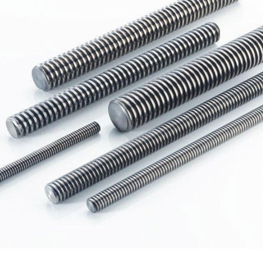
The first step in creating a grounding system that is both effective and reliable is the choice of ground rods, which play a decisive role in determining the safety and performance of the system. Out of all the different types of rods, the 1/2-inch and 5/8-inch rods are the two most common sizes, although they have different features and functions. If you are wondering how to evaluate which one is suitable for your particular grounding application, you should read this article that examines the technical aspects, performance factors, and compliance issues surrounding these two rod sizes to equip you with the knowledge to take a step forward. It does not matter if you are an electrician or just an interested homeowner; one of the very important factors in the overall effectiveness of the system is the understanding of the selection of the grounding rods.
Ground Rod Supply
Ground rods are normally supplied depending on factors like availability, grade of material, and requirements. Copper-bonded steel is the most commonly used material for ground rods since it lasts longer, has good conductivity, and is resistant to rust. The standard sizes are 5/8-inch and 3/4-inch in diameter, with lengths normally between 8 feet and 10 feet. These dimensions can effectively cover the grounding needs of both residential and commercial areas. Make sure that the rods you purchase conform to national and local electrical codes, for example, those by the NEC (National Electrical Code), to ensure that your grounding system is safe and compliant. Good suppliers and manufacturers sometimes give specified dimensions of rods to make matching your needs easy. Always check the certifications to be certain of the product’s quality and reliability.
Types of Ground Rods: 1/2 vs 5/8
The choice between 1/2-inch and 5/8-inch ground rods is not an easy one, since there are different factors to weigh: project specifications, compliance with the code, etc. The rods’ diameters are their main distinction and, thus, their performances and lifespans too.
Lightweight and generally cheaper 1/2-inch ground rods are utilized in applications with lower electrical load demands or where soil conditions permit easy driving of the rod. Still, these rods may lack the level of conductivity and durability necessary for larger or more intricate systems. Furthermore, many places only permit the use of 5/8-inch or larger rods to comply with grounding requirements.
Ground rods of 5/8-inch diameter are the ones for most residential as well as commercial settings. Their size comes with the advantage of more surface area for the current to flow through and of providing more strength, so they are guaranteed to be less sensitive to poor soil conditions. Moreover, 5/8-inch rods are mostly compliant and even exceed the requirements set by the NEC (National Electrical Code) for the grounding conductors’ minimum sizes, which are based on the effectiveness of conductivity.
In the end, it is a matter of finding the right size according to local rules, the type of electrical system, and the atmosphere. It is advisable to contact the local authorities and a qualified electrical engineer to make sure the selection and the installation are correct.
Materials Used in Ground Rods: Copper and Galvanized Options
Ground rods are usually made from copper or galvanized steel. Both materials have their unique benefits. Copper ground rods, especially copper-bonded steel rods, are the most common choice among all because of their excellent conductivity, long-lasting nature, and corrosion resistance. The copper layer makes the rod last longer in very unkind soil, thus helping the rod not to neck down as a result of the chemical reactions. These rods are most suitable for the electric performance and reliability installations, like in areas with high soil resistivity.
Galvanized steel ground rods, on the other hand, are a less expensive option, with a zinc coating that prevents the steel core from rusting. Their conductivity is somewhat lower, but they work ok in conditions where the soil is not very corrosive. They will, however, not last long under very acidic or alkaline conditions.
The selection between copper and galvanized ground rods is a matter of budget, soil composition, local environmental conditions, and regulatory standards. Copper rods are most times recommended for critical or high-performance applications, while galvanized rods are good for basic installations or where cost constraints are the major issue.
Importance of Ground Rod Clamps
Ground rod clamps are one of the most important parts of a grounding system that is reliable and efficient grounding system. Their main purpose is to tightly join the rod and the wire, which are made of conductive materials, so that the electrical contact will be constant and of very low resistance. The connection made this way will keep the faults from happening, and the voltage differences from being too large, and will also improve safety by allowing the unwanted current to flow into the earth.
These clamps are designed to cope with thermal cycling, corrosion, and mechanical wear that are common in the environment they are used. Clamps of very good quality, which are usually made from bronze, stainless steel, or copper alloys, have great conductivity and durability that are necessary for long-lasting performance. By using poor-quality clamps, the connections might be incorrect or loose, which in turn will lead to high resistance, unstable grounding, and possible system failures.
When choosing a ground rod clamp, it is important to consider the properties of the ground rod and the size of the conductor, as well as the regulations, such as the NEC (National Electrical Code), that need to be followed. Besides, proper installation and regular inspection are also very important to keep the clamp functional and to ensure that, over time, the electrical integrity is maintained.
Reviewing Ground Rod Performance
The performance of the ground rod is very much evaluated in terms of the ground conditions. Effective electrical grounding with low resistance to earth is the main target of ground rod performance. Various aspects affect the performance of the rod; among them are installation depth, soil resistivity, and rod material. Generally, a deeper installation yields lower resistance, especially in regions with high soil resistivity. Copper-bonded steel is usually the material of choice because of its excellent combination of being both conductive and non-corrosive. Regular testing (fall-of-potential test, for instance) is crucial to confirming the effectiveness of the grounding and dealing with any performance issues that might arise.
Effectiveness of Grounding Systems
The effectiveness of a grounding system greatly depends on soil resistivity, electrode configuration, and system maintenance, which are all critical factors. Of these, soil resistivity is the most powerful factor since it has a direct impact on the current fault dissipation. Different types of soil, such as clay or loam, have lower resistivity and hence help in better grounding compared to dry sand or rocky terrain. The layout of electrodes, on the other hand, is one more factor that significantly affects; good systems usually combine vertical rods, horizontal conductors, and grounding grids to ensure maximum contact with the soil surface.
Grounding systems installed and constructed with suitable materials are going to perform well in the long run. The use of copper or copper-bonded steel as materials is justified based on their excellent conductivity and resistance to corrosion. However, in addition to that, regular maintenance (which includes visual inspections and electrical testing, e.g., soil resistivity testing or fall-of-potential measurements) will ensure that the system remains functional and that degradation is timely addressed. Such processes and procedures will together make it possible for the grounding system to provide the best safety and electrical fault protection, along with conformity to the industry standards.
Installation Best Practices for Ground Rods
To maximize the efficiency and durability of ground rods, certain practices should be followed during their installation:
Selection of Proper Ground Rod Material and Size
The best ground rods will be made from excellent conducting materials such as copper-bonded steel or galvanized steel and will be of adequate size to resist corrosion in the specific area. The usual ground rod sizes are 5/8-inch in diameter and 8 feet long, but local regulations and specific needs might call for bigger or longer rods and/or different dimensions.
Correct Location and Spacing
Ground rods have to be put in less resistive soil. They should, therefore, be pushed down into soils that are moist, compact, and conductive to the full depth of the rods. If more than one rod is needed, there should be a gap between the rods that is at least 2 times the length of the rod (e.g., 16 feet for 8-foot rods). This will help in lessening interference and more grounding system efficiency.
Right Installation Depth
If the usual vertical installation is not possible due to the presence of rock or very hard ground, then the rod may be installed at an angle of up to 45 degrees or buried horizontally (depending on the installation codes). All the layers of high-resistivity soil should be completely penetrated.
Use of Ground Enhancement Material (GEM)
GEM, such as bentonite clay or conductive backfill, can be helpful in bringing up the electrical contact and lowering the overall grounding resistance significantly.
Testing and Verification
It is essential to conduct tests after the installation in order to confirm that the grounding system is really performing as planned. The use of methods such as fall-of-potential testing or clamp-on resistance measurements is common, and the resistance values are compared to those given in the safety standards, such as NEC or IEEE guidelines.
Implementing these recommendations not only boosts the grounding system’s effectiveness but also guarantees adherence to safety regulations and industry standards, thereby safeguarding operational reliability and personnel protection.
Comparative Analysis: Rebar vs Ground Rods
Rebar and ground rods are two types of grounding electrodes, which are used all the time, but they have different functions, and their respective uses on site depend on technical and design considerations as well.
| Aspect | Ground Rods | Rebar |
|---|---|---|
| Material Composition | Copper-bonded steel or stainless steel with excellent corrosion resistance | Carbon steel placed in concrete for protection |
| Durability | Excellent in wet or chemically aggressive soils | Affected by moisture or chemical exposure through concrete |
| Installation | Drive-through placement, minimal labor and equipment | Installed during building construction process |
| Cost | Generally cheaper and more versatile for new installations | Can reduce costs when already part of construction |
| Performance | Consistent and predictable with standardized dimensions | Greater surface area in concrete for better fault dissipation |
| Best Use Case | Retrofit installations or dedicated grounding systems | New construction projects with concrete foundations |
Material Composition and Durability
The primary material for ground rods is copper-bonded steel or stainless steel, both of which provide good resistance to corrosion and prolonged durability even for very wet or chemically aggressive soils. Rebar’s basic material is carbon steel, and it is mostly placed in concrete, which is an excellent protective layer against corrosion. Still, cement-reinforced steel’s longevity can be affected in places where the concrete is regularly and indirectly subjected to moisture or chemically aggressive elements.
Installation and Cost
Ground rods need no special tools or machines to be installed, as this only involves a drive-through placement into the ground, which requires minimal labor and equipment. In contrast, rebar is used in the placement foundation of structures, thus its installation time is the same as that of the building process. Nevertheless, while rebar is usually part of the construction already, using it for grounding can reduce costs, as there will be no need for the installation of a separate ground rod. But for new grounding installations, ground rods are generally cheaper and more versatile anyway.
Electrical Performance
Rebar provides a greater surface area when it is placed in concrete, which may help with the fault current dissipation rate as compared to that of a single ground rod. On the other hand, it is mandatory to check that the rebar electrodes comply with the characteristics like resistance and continuity set by the NEC standards. Ground rods present a technology that can be depended on and that gives consistent and predictable performance in a lot of grounding applications due to the standardized materials and dimensions of rods. In the case of high-resistivity soil, you may have to use several rods or add one more electrode to soil resistance needs.
Selection Criteria
The decision to use either rebar or ground rods is determined by a number of factors, including soil resistivity, environmental conditions, installation difficulty, and code requirements. Rebar is the choice when being part of a new construction project with concrete foundations, while ground rods are the best in terms of flexibility and reliability for retrofit installations or when site conditions necessitate a dedicated grounding system.
Knowing these particulars helps in choosing the right grounding electrode, which matches up with safety standards, legal compliance, and maximum system efficiency.
Ground Rod Supply Options
Electrodes are generally found in electrical supply distributors, home improvement stores, and special industrial suppliers. They come in different lengths, diameters, and material compositions that include copper-bonded steel, galvanized steel, and stainless steel to suit different applications. While picking a supplier, give preference to the trustworthy ones that meet the quality standards set by UL (Underwriters Laboratories) or IEEE, which will consequently guarantee the rod’s quality and performance. Never neglect checking whether the product specifications are in agreement with local electrical codes and project requirements before purchasing.
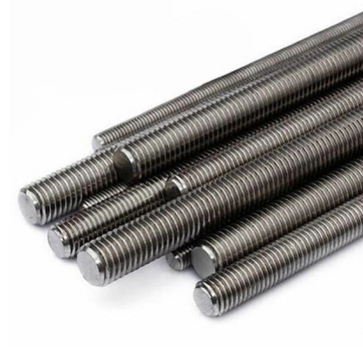
1/2 Ground Rod: Features and Benefits
A 1/2-inch ground rod is the backbone of a high-quality earthing system for electric wiring. These rods are equipped with particular features that make them versatile and perform well in different conditions. Most of the time, they are made of copper-bonded steel or stainless steel, which are not only durable but also resistant to corrosion and able to conduct electricity for a long time. Therefore, they can be used in both residential and commercial sectors. The 1/2-inch ground rod diameter is small enough to allow ease of installation even in places where the soil is packed tightly or the area is small.
Key Benefits:
- Less expensive compared to bigger counterparts
- Fulfills primary grounding requirements when installed properly
- Creates a low-resistance route for electrical faults or lightning strikes
- Easy and safe conveyance of electrical energy into the ground
- Prevents damage to equipment
- Lowers chances of electrical hazards
- Easy installation in tight or compact soil areas
To ensure that they are calling for compliance and giving the best performance, the rods have to be of UL class 467 and NEC (National Electrical Code) or even better than that. Correct installation and favorable soil conditions are key to the grounding rod being as effective as it can be.
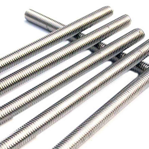
5/8 Ground Rod: Features and Benefits
The 5/8 ground rod can be viewed as a highly dependable element within the electrical grounding systems, meant to provide high-performance and long-lasting durability. Usually, these rods are made of copper-bonded steel, which gives them excellent corrosion resistance and a long service life even in very severe environmental conditions. The copper-bonding technique guarantees a low-resistance route for the safe dissipation of electric currents into the ground, thus avoiding electrical faults and reducing the chance of damage to the equipment.
One of the specific characteristics of the 5/8 ground rod is its conformance to the widely accepted industry standards like UL 467 and NEC regulations, which is a guarantee of safety and performance. The rod’s standard 5/8 inches diameter assures maximum conductivity, while the lengths of 8 to 10 feet give better soil contact for the greatest dissipation of electrical energy. Moist or conductive soil is the perfect soil compatibility that will further boost its efficiency.
Key Advantages:
- Good fault current dissipation
- Fewer electrical hazards
- Long life even in extreme environmental conditions
- Suitable for residential, commercial, and industrial applications
- Inexpensive grounding systems with assured durability
- Excellent corrosion resistance
- Maximum conductivity with 5/8 inches diameter
- Better soil contact with 8 to 10 feet lengths
These rods find their use in various places, like residential, commercial, and industrial; they are inexpensive grounding systems that assure the durability of grounding systems when properly installed.
Choosing Between Copper and Galvanized Options
| Feature | Copper Ground Rods | Galvanized Ground Rods |
|---|---|---|
| Conductivity | Excellent – superior electrical conductivity | Good – adequate for most applications |
| Corrosion Resistance | Excellent – highly resistant in corrosive soils | Moderate – zinc coating provides protection |
| Longevity | Long-lasting even in harsh environments | Shorter lifespan in acidic or saline soils |
| Cost | Higher initial investment | Lower cost, budget-friendly option |
| Best Applications | High-performance systems, corrosive soil environments | Less corrosive environments, cost-sensitive projects |
| Maintenance | Minimal maintenance required | May require more frequent inspection |
Both copper and galvanized grounding rods are employed widely, with the choice dependent on factors such as conductivity, longevity, cost, and the environment where they have to be installed. Copper grounding rods (either solid or copper-bonded), on the other hand, ensure better conductivity and resistance to corrosion; hence, they are employed for high-performance grounding systems or in highly corrosive soils. They are generally more costly than their galvanized counterparts.
Whereas a galvanized grounding rod is coated with zinc against corrosion and is lower in price, it gives sufficient performance for many applications, yet loses out when it comes to life in some soils, particularly in those that are highly acidic or saline, because the zinc coating gradually dissolves.
Deciding between the two requires an assessment of soil resistivity, environment, and cost. Copper rods are used when installations demand the highest durability and conductivity. Galvanized rods are favored for projects in less corrosive environments where cost is a factor.
Grounding Techniques and Best Practices

Effective grounding techniques provide essential safety to any electrical system. The following best practices are recommended for a good grounding procedure:
- Choose Appropriate Grounding Electrodes
Depending on soil and environmental conditions, grounding electrodes should be chosen; copper or galvanized rods are an option. Copper electrodes are best used where potential exists for high corrosion, whereas galvanized rods are cheaper in non-corrosive soils. - Provide for Proper Depth of Installation
Grounding electrodes should be driven to a proper depth, generally below the frost line, so as to maintain consistent conductivity and to avoid changes as per season. - Provide for Low Soil Resistivity
If required, make the soil moist, salty, or bentonitic for good conductivity. This is the best way to reduce resistance and safely dissipate fault currents. - Check Connections and Continuity
Secure all connections and look for signs of corrosion or damage. Ensure there is continuity throughout the grounding system by means of a suitable testing device. - Regular Inspection and Testing
Grounding systems shall periodically be tested for safety standards and performance. The usual methods include ground resistance testing, either by clamp meters or fall-of-potential procedures.
If adhered to, these best practices guarantee a strong and reliable grounding system that ensures electrical safety and system efficiency.
Importance of Proper Grounding in Electrical Systems
Proper grounding in electrical systems is of utmost importance for safety, system reliability, and equipment protection. The earth provides a path through which electrical energy can safely dissipate, especially during faults such as lightning, short circuits, or static discharge. Grounding, therefore, helps prevent electrical fires, damage to equipment, or personal injury by diverting any excess current from sensitive system components and users.
In reality, grounding functions stabilize the voltage levels within the system, lessening random behavior and potential scenarios of overvoltage incidents that weaken operational integrity. Touching upon protective devices such as circuit breakers, grounding permits these devices to perform their duties in swiftly isolating faults. Grounding, moreover, is required by codes and standards such as NEC and IEC, laying down design and performance criteria for safe electrical installations.
An efficient grounding system mitigates damage during electrical surges and faults, thus providing continuity of service and increasing equipment lifespan. Hence, the grounding system would require regular maintenance and testing to retain safety and operational efficiency. Non-conformance to grounding regulations can have disastrous consequences in terms of equipment failures, safety hazards, and penalties for non-compliance. Therefore, in any modern electrical installation, an adequate grounding provision is not just a technical requirement; it is a fundamental requirement.
Installation Tips for Ground Rods
Installing the ground rod is very important to ensure the effectiveness of an electrical ground system. Consider a few brief tips below, according to good practice and generally recommended methods:
- Location Selection
Choose a location far from obstructions and every kind of utility line, with the soil moisture level on the higher side to enhance conductivity. Avoid rocky and dry places where the efficiency of the ground rod could be compromised. - Rod Material and Size
Use rods of materials with the highest possible conductivity, like copper or copper-bonded steel. With regard to the size, the length should be at least 8 feet, and its thickness should be 5/8 inches, according to NEC Standards. - Driving of Rod
Driving into the ground must be done in a vertical position with a sledgehammer or a mechanical ground rod driver. Carefully ensure that the rod is fully in contact with the surrounding soil so that conductivity and stability are maximized. If it is not practical to install the rod in the vertical position, it may then be set at an angle not exceeding 45 degrees or buried horizontally. - Connection to the Ground Electrode Conductor
The grounding electrode conductor shall be securely fastened to the rod using approved clamps or connectors that must be durable and corrosion-resistant. - Testing and Verification
Ground resistance tests shall be carried out using an earth tester on the rod to check whether it is within the required resistance value of usually less than 25 ohms, as recommended by the accepted standards. When the resistance is beyond the required figure, it shall no longer be acceptable to apply additional ground rods at intervals not less than twice the length of that rod and interconnecting them.
Following these steps will ensure the grounding system performs optimally, complies with all codes, and is reliable throughout its lifetime.
Using Ground Rod Clamps Effectively
Ground rod clamps are the ones that create a secure and electrically efficient connection between the ground wire and the grounding rod. To use ground rod clamps properly, one must first select clamps that will offer high electrical conductivity and corrosion resistance, such as bronze or stainless steel, to guarantee such performance when exposed to certain conditions. They must then be properly installed by tightening to the torque value specified by the clamp manufacturer; likewise, this is to secure the connection firmly without applying undue pressure on the conductor.
The clamp must be compatible with the ground rod and conductor being used. Inspection and maintenance are then required to check for corrosion or wear and for loose connections that could destroy the integrity of the grounding system. Also, clamps should be installed according to the NEC standards, e.g., Article 250, to ensure safety and proper performance so as to maintain the effectiveness of rod clamps in electrical grounding systems.
Review of Ground Rod Products
Ground rods are necessary for achieving proper grounding, for which different types exist to suit different applications and environments. Copper-bonded steel rods are generally highly revered for their conductivity and corrosion resistance. Typically, an 8-foot rod with a 5/8-inch diameter works fine and complies with NEC standards for most residential and commercial installations. Rods must be UL-467 certified to guarantee reliability and safety. Another thing to consider is the resistivity of the soils at the installation site, as this can affect the rod’s performance. A good company will have charts that show variations in resistivity and installation instructions to aid product selection.
Comparative Analysis of 1/2 and 5/8 Ground Rods
The prominent differences between half-inch and 5/8-inch rods lie mainly in the factors of strength, conductivity, and standard requirements. A 5/8-inch ground rod is usually stronger because of its diameter and, thus, it offers some resistance to bending or damage during installation. It also offers less resistance against electrical current, so grounding ability is enhanced. Needless to say, the 5/8-inch rod meets the NEC standards for residential and commercial use, while in some areas, a 1/2-inch rod would not qualify. For almost all installations, the 5/8-inch ground rod is used because of better performance and better acceptance.
| Comparison Factor | 1/2-Inch Ground Rod | 5/8-Inch Ground Rod |
|---|---|---|
| Strength | Lighter, less resistant to bending | Stronger, better resistance to damage during installation |
| Conductivity | Adequate for basic applications | Lower electrical resistance, enhanced grounding ability |
| NEC Compliance | May not qualify in some areas | Meets NEC standards for residential and commercial use |
| Installation | Easier in tight spaces and compact soil | Requires more force but provides better stability |
| Cost | Generally cheaper | Slightly higher cost but better value |
| Performance | Suitable for lower electrical load demands | Better overall performance and acceptance |
| Recommended Use | Basic installations, small projects | Most installations, preferred choice |
Top Ground Rod Clamps in the Market
Selecting the proper ground rod clamp is imperative in guaranteeing a tight connection between the ground rod and the grounding conductors. See below for three highly recommended clamps drawn from an assessment of various industry sources:
1. Burndy GAR-B Series
Burndy GAR-B clamps are the first choice for heavy-duty applications and reliable performance. These clamps are made using a copper alloy of high conductivity, which gives the best corrosion resistance, along with superior mechanical holding properties. Because they are UL-listed, these clamping devices are available for use with a variety of rod sizes in the residential and commercial sectors.
2. ILSCO GRC Series
Made of bronze alloys, the ILSCO GRC series of clamps passed the test for great conductivity over long-term performance. Designed for quick installation, these clamps fit 1/2-inch to 1-inch rods and various conductor sizes. Their corrosion-resistant treatment protects immediate reliability in aboveground and underground service.
3. Erico LTE Copper-Bonded Clamps
Employing high-strength copper-bonded steel, Erico LTE females offer a good balance between affordability and high performance. They grab the rod tightly while allowing low resistance to electricity, very important for proper grounding. Since they are usable with various types of ground rods, they have gained popularity amongst the industries.
These options represent an industry standard and give good performance, thereby complying with legal requirements while offering long-term grounding efficiency.
User Reviews and Feedback on Ground Rods
I consider ground rods to be a reliable component for effective electrical grounding in any application. In particular, their strength and corrosion resistance provide long life even in extreme conditions. They are easy to install and connect with clamps such as the L. T. E., adding to their versatility. Overall, the experience was positive in that they have always met industry standards and project requirements.
Conclusion
Selecting the right ground rod is a critical decision that impacts the safety, performance, and compliance of your electrical grounding system. Whether you choose a 1/2-inch or 5/8-inch ground rod depends on various factors including your project specifications, local code requirements, soil conditions, and budget considerations.
The 5/8-inch ground rod stands out as the industry standard for most residential and commercial applications, offering superior strength, better conductivity, and full compliance with NEC standards. While the 1/2-inch rod may be suitable for specific applications with lower electrical demands, the 5/8-inch option provides better long-term value and performance.
Remember that proper installation, quality materials, appropriate clamps, and regular testing are just as important as selecting the right rod size. Always consult with local authorities and qualified electrical engineers to ensure your grounding system meets all safety standards and performs optimally for your specific application.
By following the best practices outlined in this guide and choosing quality materials from reputable suppliers, you can create a grounding system that provides reliable protection for years to come.
Reference Sources
Perancangan Sistem Pentanahan Gedung Pusat Komputer Universitas Negeri Manado
Frequently Asked Questions (FAQs)
What difference exists between 1/2 and 5/8 ground rods?
The primary difference between 1/2 and 5/8 ground rods is in their diameter and the rigidity they provide. Usually, the 5/8 ground rod offers a thicker conductor with more durability and is, therefore, suitable for more demanding applications.
Are 1/2 or 5/8 ground rods UL listed?
Yes, both 1/2 and 5/8 ground rods can be UL listed; this means they conform to underwriters’ standards for safety. Make sure to check the package or product specification to determine if the product is a UL-listed product.
How do I direct-bury a ground rod?
Direct burial is done by selecting an obstruction-free place and hammering the rod into the ground vertically. The rod should be buried at least 8 ft deep in accordance with the code for the best ground.
What supply is required for installing a ground rod?
Any supply needed for installing a ground rod usually consists of the ground rod itself, a hammer or driver, grounding clamps, and grounding wire. It might also be a good idea to carry a shovel for any digging that has to be done.
What is the inspector looking for in terms of ground rods?
An inspector wants to verify the proper installation of the ground rods, which includes checking for depth and making sure that the rods have been properly attached. They also check for corrosion or damage that may be evident to the eye. Passing inspection requires compliance with all local codes.
Can I use a 1/2 ground rod for my electrical works?
The use of a 1/2 ground rod is accepted with certain electrical systems. However, it is generally recommended to have a ground rod of 5/8 inches for better performance and security, mainly if the soils have high resistivity or whenever a reliable ground is necessary.
What is the recommended list for ground rod sizes?
Depending on ground rod sizes, 1/2 inch rods and 5/8-inch rods are generally on the recommended list, so other sizes are rarely or never used. Please note that 5/8-inch rods are considered more effective for grounding and are most commonly used for residential and commercial applications.