Wiring a 50-amp shore power plug demands pinpoint accuracy and safety. Whether you are upgrading your RV, connecting the boat, or developing a portable power system, it is essential to learn the correct wiring diagram for the best and safest performance. This article thoroughly explains the parts, connections, and the best method to wire a 50-amp shore power plug. By the time you finish reading this post, you will be well versed in wiring, safety issues to consider, and suggestions for the efficient and safe operation of your system.
Understanding 50 Amp Shore Power
A shore power system with a capacity of 50 amps is the traditional way to supply certain RVs, boats, or portable systems with electricity from an outside source. The system operates on a 4-wire configuration: two hot wires at 120 volts each, one neutral wire, and one ground wire, capable of delivering a total maximum power of 12,000 watts. This setup supports equipment requiring either 120 volts or 240 volts, hence supplying greater power than do 30-amp systems. Always make sure when plugging into shore power that the configuration matches that of the power pedestal and adhere to all safety instructions to avoid any electrical hazards.
What is Shore Power?
Shore power is electricity supplied by a land-based source to stationary vehicles, vessels, or equipment, keeping their operations going without depending on an onboard source such as an engine or generator. Shore power, essentially marine and RV-related, is of utmost importance for powering systems and appliances while docked or parked. Shore power usually involves connecting to a power pedestal or outlet with a standard plug arrangement. Among standard shore-power connections are the 30-amp and 50-amp systems, which serve any number of electrical needs to include lighting, heating, cooling, and other basic activities. The use of shore power helps in noise reduction and fuel consumption in an emission-generation system. Keeping shore power operational includes making sure the voltage and amperage required match what is supplied, thereby preventing unsafe operations and electrical faults.
Importance of 50 Amp Connection
Higher energy needs result in a 50-amp shore power connection that supports them, in particular for larger RVs, boats, or other systems that require an electric load. Two 120-volt lines at 50 amps each are shipped out when such a connection is established; one can achieve as much as 12,000 watts of power output, in this way creating a considerably heavier option than the 30-amp connection. Greater capacity assures appliances with heavy-energy usage, such as air-conditioning units, water heaters, refrigerators, and entertainment systems, from operating together without the possibility of being overloaded or having breakers tripping. Another advantage is the 50-amp power supply, said to be more reliable and efficient; it decreases voltage drops, ensuring equal functioning of all connected appliances. If safety and functionality are to be ensured, then utmost care, such as using legal adapters and recommended specifications, should be considered.
Components of a 50 Amp System
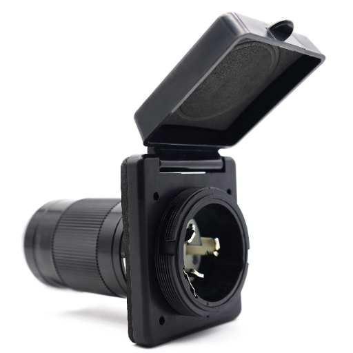
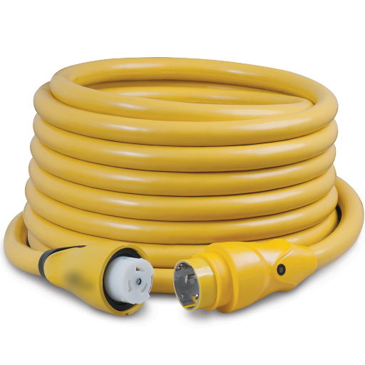
The vast majority of 50-amp electrical systems generally consist of a few key components, all aimed at effective and safe power distribution. The heavyweight power cord stands central in this system, as it transmits electricity from a power source to the production/slash distribution panel. The power cord has a corresponding plug and receptacle that features four prongs-two hot wires, each at 120 volts, one neutral, and one ground wire. This configuration allows the system to either provide 240 volts or two 120-volt circuits, so power is supplied equally.
Distribution panels ensure another crucial service, keeping circuit breakers between the supply and the circuits to protect from overloading or short-circuiting. Alongside these breakers, wiring rated for 50 amps is laid into the system, as it has to take on the current load without producing unusual heat.
Additional accessories, such as voltage surge protectors and certified adapters, bring an extra degree of protection and adaptability to the system. Surge protectors shield the devices from spikes in voltage, while an adapter makes two different types of plugs compatible. Correct installation, as well as regular maintenance of these components, should be applied to guarantee both long life and smooth operation of the whole system.
Wiring a 50 Amp Shore Power Plug
To wire a shore power plug of 50 amp safely and efficiently, procure the tools and materials, and follow the procedure.
Tools and Materials Needed
- A 50 Amp plug
- Compatible cable (usually a 6/3 and 8/1 wire combination)
- Screwdriver
- Wire strippers
- Multimeter for testing
Wiring Configuration for Understanding
Generally, the 50 Amp shore power plug has four wires:
- Black (hot) connects to one of the “X” terminals for 120V.
- Red (hot) connects to the other “Y” terminal for 120V.
- White (neutral) connects to “W”.
- Green (ground) connects to “G”.
Installation Steps
1Cable Preparation: Strip the outer insulation from the cable. Then strip about half an inch of insulation from all four internal wires.
2Connect the Wires: Use a screwdriver to securely fasten each wire to its proper terminal inside the plug, matching the color of the wire (black, red, white, green) to the respective terminal label. Make sure the connections are tight enough so as not to let the device go, but do not over-tighten and risk damage to the device.
3Inspect and Test Connections: Make sure each wire is in its proper terminal, with no offending strand sticking out here or there. Use a multimeter to also test for continuity and suitable connections.
4Fasten the Plug Body: After connecting and testing all wires, replace the plug cover while making sure that all screws are well-tightened and that the cable is clamped well to avoid any strain on the wiring.
Important Note: Always observe local codes and wiring standards. When uncertain about it, or with the beads, consult a licensed electrician to guarantee safety and compliance.
Tools Required for Wiring
Some essential tools for efficient and safe wiring jobs consist of the following:
- Wire Strippers: To remove the insulation from electric wires cleanly and without damaging the conductor.
- Screwdrivers: A set of insulated screwdrivers, including flat and Phillips tips, used to tighten connections and terminal screws.
- Multimeter: Measures voltage, continuity, resistance, and detects electrical faults.
- A Voltage Tester: Confirms that circuits are de-energized before any wires are handled to prevent electric shock.
- Pliers: Needle-nose and combination pliers are used for gripping, bending, and shaping wires, or for the assembly of small components.
- Cutters: Cut large wires or cords cleanly without crushing the conductor.
- Electrical Tape: Used for insulating wires and securing loose connections.
- Wire Nuts and Connectors: To safely join two or more wires while maintaining electrical integrity.
- Fish Tape: It helps pull wires through conduits or walls during installation over a long distance.
- Utility Knife: Handy while delicately separating cable sheathing during the preparation stages.
Note: These tools basically lay the foundation of safe and effective wiring practices. Check to make sure that your tools are in a good working condition and are rated accordingly to the electrical application intended.
Step-by-Step Wiring Diagram
Step 1: Plan the Wiring Layout
Identify the electrical needs and design the wiring paths in a corresponding manner. Factor in the outlets, switches, and fixtures that will be required while also making sure that the local electrical codes are followed. Draw a rough sketch so that the connections can be visualized.
Step 2: Shut Off Power
Deactivate the power at the circuit breaker panel so that electrical accidents do not happen during the installation process. After that, take a voltage tester and check that the wires are not live before you start working.
Step 3: Set Up Electrical Boxes
Mount the electrical boxes firmly at the places selected for outlets, switches, and fixtures. Make sure that the boxes are even with the wall surface and are the right size for the number of wires and connections inside them.
Step 4: Cables to Run
Run the power cables through the walls, conduits, or studs that are open according to the layout. In case it’s hard to pull the cable, use a fish tape and make sure to hold the cable properly with staples or clamps that are spaced according to code. Always leave some extra cable for each connection point.
Step 5: Connections to Make
Remove the cable sheathing, and cut the individual wires to the desired length. If you need to strip the insulation off without damaging the wires inside, use a wire stripper. Connect matching wires (hot, neutral, and ground) using wire nuts, making sure that the connections are strong and secure.
Step 6: Install Fixtures and Devices
Light fixtures, outlets, and switches will be attached to their electrical boxes. Installation according to the manufacturer’s instructions will be followed, and the wires will be connected to their respective terminals. Connection will be done with the right torque so that no loose connections occur.
Step 7: Test the Circuit
Reset the circuit by turning the power supply back on at the breaker. A multimeter can be used to measure continuity and proper voltage levels at all fixtures and outlets. The working of the whole circuit should be verified, and look out for any faults.
Step 8: Finalize and Secure
The remaining cables will be neatly arranged inside the boxes, faceplates will be secured, and all the connections will be checked again. The circuit will be labeled accordingly at the breaker panel for future reference.
Key Takeaway: By following these steps one after another, you will be able to implement a wiring installation that is safe, operational, and up to code requirements.
Common Mistakes to Avoid
Overloading Circuits
One of the most typical mistakes is to overload one circuit by connecting numerous fixtures or outlets, which may result in frequent tripping of circuit breakers or, in extreme cases, overheating and fire risks. Always do the load capacity calculation and then place it in accordance with the electrical code requirements.
Using Incorrect Wire Sizes
Wrong wire sizes corresponding to the current load are a common problem. The insulation breakdown could lead to the wire’s overheating and, subsequently, an electrical fire. Check the wire gauge charts for proper sizing according to amperage and circuit length.
Improper Grounding
Improper grounding of a circuit or total omission of it weakens the electric system’s safety. Ground all lamps, sockets, and panels in the right way to minimize the risk of electric shocks or damage during faults.
Loose or Poorly Connected Wires
Loose connections could result in sparks, arcing, or temporary power issues. Make sure that all wire connections are done right and use the recommended connectors to have tight and secure contacts.
Ignoring Electrical Codes
Ignoring electrical codes, both local and national, could lead to dangerous electrical systems and legal problems. Always follow the most up-to-date standards, such as the NEC (National Electrical Code) and others, for compliance assurance.
Failing to Turn Off Power
Working on a live circuit without first turning off the power at the breaker panel is very dangerous, as it increases the risk of electric shock. Always check with a dependable voltage tester that the circuit is not live before you start working.
Remember: Steering clear of these mistakes will reinforce the safety, dependability, and life expectancy of your electrical installations.
Installing a 50 Amp Plug in RVs
Gather Necessary Equipment
Make sure that you have the following items: a 50-amp RV outlet, a suitable electric box, a 50-amp breaker, suitably sized wires (usually 6-gauge), a screwdriver, a wire stripper, and a voltage tester.
Turn Off Power
Switch off the power at the main circuit panel to reduce the possibility of electric shock. A voltage tester should be used to check that the circuit is not live.
Install the Electrical Box
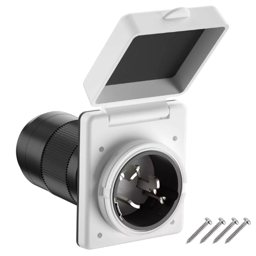
Fix the electrical box in the location you want to install it, and if it is going to be outside, make sure it is weatherproof.
Connect the Wires
The wires should be taken from the breaker panel to the outlet. The wires should be connected to the outlet terminals as listed below:
- Black and red wires to the hot terminals.
- The white wire is connected to the neutral terminal.
- The green or bare copper wire to the ground terminal.
Install the Breaker
Place a 50-amp breaker in the main breaker panel. Connect the wires from the outlet to the breaker (hot wires), to the neutral bus bar (white wire), and to the ground bus bar (green/bare wire).
Test the Outlet
Restore the power and use a voltage tester or multimeter to check the correct connections and voltage at the outlet point.
Important: Carrying out these procedures, the 50 amp plug for RVs is assured to be safe and working. If there is any uncertainty about a certain step, seek advice from a licensed electrician.
Choosing the Right Receptacle
All things considered, taking into account the factors mentioned above, the most appropriate receptacle for a 50-amp RV plug would be NEMA 14-50. In general, a 50-amp RV plug is compatible with a NEMA 14-50 receptacle. This receptacle has four prongs (two hot, one neutral, and one ground) and is rated for RVs, providing 240 volts and up to 50 amps.
If the receptacle is going to be located outside, make sure it is rated for outdoor use. Also, use a weatherproof cover to protect it from environmental damage. As a matter of fact, the receptacle should be a mirror image of your RV’s power cord for smooth and hassle-free connectivity. Moreover, it is always recommended to buy UL-listed products as a guarantee that they comply with the safety standards of the country. The appropriate selection and installation of the receptacle are vital for the safety and efficiency of your RV’s electrical system.
Connecting the 50 Amp Plug
In connecting a 50-amp plug, first make sure the power source is properly and completely de-energized to avoid any risk of electrical accidents. Then, position the plug’s blades to match the slots in the receptacle. The 50-amp plug has a design that consists of four prongs, which include two “hot” prongs, one neutral prong, and one prong for ground. Then plug the receptacle in completely and securely, making sure there is a good connection without forcing it. Check that the wiring in the receptacle is standard for 50-amp RV power configurations, which provide 120/240 volts. When you are done connecting, turn the power back on and use a multimeter to test the connection to make sure the voltage is correct and stable. During use, always look for indications of damage or overheating and take care of the problems immediately to ensure safe operations.
Testing the Installation
For the purpose of making sure that the installation is working correctly and is safe, do the following steps one after another with care:
Check Voltage Output
With the help of a multimeter, check the voltage at the socket. If it is a 50-amp RV outlet, the multimeter reading should be about 120 volts between each hot terminal and neutral, and 240 volts when the two hot terminals are measured. Any readings that are out of range indicate either faulty power connections or wrong wiring done on the circuit.
Check Grounding
Ensure the socket is grounded correctly by checking continuity from the ground terminal to an earth point. Grounding that is done right will avoid the occurrence of electrical hazards that may range from shocks to surges in power.
Test Load Capacity
Connect a large load like an RV or a heavy-duty testing device if required. While the RV is operating, monitor the power connection for even delivery. Check for overheating in the area of the power connection, which can be indicated by melted insulation and strange odors, and also ensure that no circuit breakers are tripped under normal operating conditions.
Perform Polarity Checks
A circuit tester should be used to verify that the polarity is right. The hot and neutral terminals must not be interchanged because reversed polarity creates a danger to both users and equipment.
Last Visual Inspection
Inspect all the connections and the receptacle housing for any signs of wear, loose parts, or corrosion. Take immediate action with regard to any shortcomings to ensure that the system remains intact.
Key Point: By completing these steps in an orderly manner and rectifying any errors discovered during testing, the reliability and safety of the installation for continuous use can be assured.
Understanding the 50 Amp Wiring Diagram
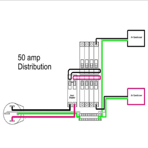
A 50-amp wiring diagram presents the necessary links for the safe supply of 240 volts with a total power of 50 amps to a particular outlet or device. This diagram usually comprises four distinct wires: two “hot” wires (each of which is 120 volts), one neutral wire, and one ground wire. The hot wires are attached to the two terminals of a double-pole breaker to get the 240 volts, while the neutral wire makes the circuit complete, and the ground wire provides safety by grounding the system. This type of configuration is common for high-power appliances like RVs, electric ranges, or big tools, letting the power get through and safety be increased at the same time.
Reading the Wiring Diagram
It is very important to learn how to read a wiring diagram, as it will help you to safely install and operate electrical systems. Usually, the wiring diagram will start with making the symbols for the switches, outlets, breakers, and connections, etc., which are the main components of the circuit. Usually, 240-volt wiring diagrams show two hot wires, a neutral wire, and a ground wire, with paths clearly pointing out how the circuit is connected.
Tracing back to the power source, which goes into the panel, and then following the flow of electricity through the circuit should help you to read the diagram properly. Make sure you notice the junction points where wires may be split or joined together so that the diagram may be compared with the actual wiring layout. Also, check if the colors of the wires are indicated correctly- black and red are usually the hot wires, white and neutral, and green or bare wire is for grounding.
On top of that, if you want to be sure that the device is compatible with your setup, check its voltage and amperage requirements. In most cases, the wiring diagrams will contain explanations or a legend for proper understanding. The strict compliance with the National Electrical Code (NEC) as well as the manufacturers’ instructions is a must for safety and legality. By breaking down the diagram, you will be able to have your electrical setup functioning and being reliable at the same time.
Color Codes and Their Meanings
Knowing color codes in electrical wiring is very important to keep a system safe and working properly. The standardization of wire colors is usually determined by regulations like the National Electrical Code (NEC) in the U. S. Below is a brief description of the most common wire colors and what they symbolize:
| Wire Color | Function | Description |
|---|---|---|
| Black Wires | Hot/Live | They are used for transferring live or “hot” currents. They are the main electricity carriers in circuits and should always be treated with care. |
| Red Wires | Secondary Hot | These usually act as the secondary live wires in 220V setups or as switching lines, which means they connect switches to loads. |
| White or Gray Wires | Neutral | Usually perform the role of neutral wires. They complete the circuit by sending the current back to the source. |
| Green Wires or Bare Copper | Ground | Only for grounding and making the path for electricity to go safely, which lessens the risk in case of faults. |
| Blue and Yellow Wires | Special Circuits | These are sometimes used as “hot” wires in special circuits like travelers in three-way switch setups. |
Important: The right reading of these color codes is very important when it comes to maintenance or the installation of electrical systems. Additionally, it is a good practice to check with the local codes and the standards because wiring practices could be different.
Safety Considerations
When dealing with electrical wiring, safety is and will always be the first priority, and several practices should be followed that would help prevent accidents or system failures. Even if it is just one circuit, always confirm that power is switched off at the breaker before doing any work on it. Make use of a voltage tester to check that there is absolutely no current flowing in the wires before you start working on them. Also, wear insulated gloves, and for your tools, non-conductive handle ones are recommended to lower the risk of an electric shock. Besides, limit the circuits by following the ampacity and securing all the connections to avoid arcing or heating up.
It is very important to follow local electrical codes and standards, as these regulations are meant to protect against hazards. Wires are less prone to mistakes if the proper labeling and organization are done during the installation. If you are dealing with complicated or unfamiliar systems, do not hesitate to seek the help of certified professionals who can guarantee safety and compliance with the standards. Moreover, to keep the risks to a minimum, regular inspections and maintenance can be done, thereby ensuring that the electrical system is always safe and functional over time.
50 Amp vs 30 Amp Shore Power
The major difference between 50-amp and 30-amp shore power is the usage of electrical power. The maximum that a 30 amp system can provide is 3,600 watts (30 amps x 120 volts), while the 50 amp system can provide up to 12,000 watts (50 amps x 240 volts), making it triple the power. That is why 50 service is for larger boats or RVs where several units like A/C, fridges, and entertainment systems are running at the same time, requiring more power to keep them running. In contrast, the 30 amp system can be used for the small campers with few power requirements as it’s often enough. Always check that the power supply of your boat’s electric system matches the shore power connection so you do not overload or damage it.
Differences in Power Supply
The main distinction between the 30-amp and 50-amp power supplies is their power capacity and wiring configuration. A 30-amp system uses one hot wire, one neutral wire, and a ground wire; thus, it can provide a maximum power of 3,600 watts (30 amps x 120 volts). This arrangement is normally adequate for small RVs or boats where not many electrical devices or appliances are used.
On the contrary, a 50-amp system consists of two hot wires, one neutral wire, and a ground wire, which practically increases the power available by two times. Each hot wire provides 120 volts, and thus the total power is 12,000 watts (50 amps x 240 volts). Hence, a 50-amp system is suited for big, demanding, high-power setups like those having several air conditioners, large kitchen appliances, and sophisticated sound systems.
It is very important to identify the electrical system of your RV or boat with the power supply when determining compatibility. An adapter can facilitate the connection of 30-amp and 50-amp systems, but it is important to be careful not to overload the system or destroy the equipment.
When to Use 30 Amp vs 50 Amp
Knowing when to apply 30-amp or 50-amp systems relies on the power requirements of your entire setup. I switch on the 30-amp system for my minimal energy needs, like powering small gadgets, lighting, and one air conditioner. But when using heavy appliances, like simultaneous operation of three air conditioners or a big fridge with other energy-consuming devices, I go for a 50-amp system. The 50 amp setup enables me to have a big power supply, which is perfect for always saying goodbye to circuit overloads when managing high-demand setups.
Adapters and Compatibility
When dealing with RV electrical systems, one of the most important things to do is to understand adapters and ensure that they are compatible to avoid the risk of damage or lost efficiency. Adapters are used to connect circuits of various amp ratings (for instance, connecting a 30-amp RV to a 50-amp power outlet or the other way around). The 30-to-50 amp adapter increases the connection, supplying 30 amps maximum to your RV even though it is plugged into a 50 amp outlet. On the other hand, the 50-to-30 amp adapter lowers the power being drawn in order to fit a 30 amp outlet.
You should be aware of the fact that the adapters do not increase the power that your RV’s wiring can carry; at the same time, they offer you the flexibility to use different power sources. If you use an adapter improperly or if you overload the circuits, the devices may get damaged or overheated. It is advisable to check that the amp limit of your configuration is not exceeded by your appliances and systems. Also, the prongs and voltage rating of your adapter should match the power source specifications and your RV connection in order to avoid any electrical faults or hazards.
Comparison Summary: 30 Amp vs 50 Amp Shore Power
| Feature | 30 Amp System | 50 Amp System |
|---|---|---|
| Maximum Power | 3,600 watts (30A x 120V) | 12,000 watts (50A x 240V) |
| Wire Configuration | 3-wire (1 hot, 1 neutral, 1 ground) | 4-wire (2 hot, 1 neutral, 1 ground) |
| Voltage | 120 volts | 120/240 volts |
| Best For | Small RVs, boats with minimal appliances | Large RVs, boats with multiple high-power appliances |
| Typical Use | Lighting, small appliances, single A/C | Multiple A/C units, water heaters, full kitchen appliances |
Summary: Key Takeaways for 50 Amp Shore Power Wiring
Wiring a 50 amp shore power plug is a critical task that requires precision, proper tools, and adherence to safety standards. Throughout this comprehensive guide, we have covered all essential aspects of 50 amp shore power systems, from understanding the basic components to completing a safe and functional installation.
Understanding the System: A 50 amp shore power system operates on a 4-wire configuration delivering up to 12,000 watts of power, making it ideal for larger RVs, boats, and portable power systems with high electrical demands. This configuration consists of two hot wires at 120 volts each, one neutral wire, and one ground wire, providing both 120-volt and 240-volt capabilities.
Critical Components: The system includes a heavy-duty power cord with a corresponding plug and receptacle featuring four prongs, distribution panels with circuit breakers, properly rated wiring, and additional accessories such as surge protectors and certified adapters for enhanced protection and versatility.
Wiring Process: Successful installation requires careful cable preparation, proper wire connection following color codes (black and red for hot, white for neutral, green for ground), thorough inspection and testing, and secure fastening of all components. Each step must be performed methodically to ensure both safety and functionality.
Safety First: Always turn off power at the breaker before beginning work, use appropriate testing equipment to verify circuits are de-energized, wear proper protective gear, follow local electrical codes and NEC standards, and consult licensed electricians when uncertain about any aspect of the installation.
Common Pitfalls to Avoid: Be mindful of circuit overloading, using incorrect wire sizes, improper grounding, loose connections, ignoring electrical codes, and working on live circuits. These mistakes can lead to serious safety hazards, equipment damage, and system failures.
Testing and Verification: After installation, comprehensive testing is essential. Check voltage output (120V between each hot and neutral, 240V between the two hot wires), verify proper grounding, test load capacity under actual operating conditions, perform polarity checks, and conduct thorough visual inspections for any signs of wear or damage.
30 Amp vs 50 Amp: Understanding the difference between these systems is crucial for selecting the right setup. While 30 amp systems (3,600 watts) are suitable for smaller RVs with basic needs, 50 amp systems (12,000 watts) are necessary for larger vehicles with multiple high-power appliances running simultaneously.
By following the detailed instructions, safety guidelines, and best practices outlined in this guide, you can successfully wire a 50 amp shore power plug that will provide reliable, efficient, and safe power delivery for years to come. Remember that electrical work can be dangerous if not performed correctly, so always prioritize safety and don’t hesitate to seek professional assistance when needed.
Final Safety Reminders
- Always De-Energize: Never work on live circuits. Always turn off power at the breaker and verify with a voltage tester.
- Use Proper Tools: Invest in quality, properly rated tools including insulated screwdrivers, wire strippers, and reliable testing equipment.
- Follow Color Codes: Strictly adhere to wiring color standards – black and red for hot wires, white for neutral, green or bare copper for ground.
- Verify Connections: Double-check all connections for tightness and proper terminal placement before energizing the system.
- Test Thoroughly: Use a multimeter to verify voltage levels, continuity, and proper grounding before putting the system into service.
- Match Ratings: Ensure all components (wire gauge, breakers, receptacles) are properly rated for 50 amp service.
- Weatherproof Outdoor Installations: Use weatherproof boxes and covers for any outdoor receptacles to prevent environmental damage.
- Label Everything: Clearly label circuits at the breaker panel for easy identification and future maintenance.
- Regular Inspections: Periodically inspect connections, receptacles, and plugs for signs of wear, overheating, or corrosion.
- Know Your Limits: If you’re unsure about any aspect of the installation, consult a licensed electrician. Safety is always worth the investment.
- Keep Documentation: Maintain records of your installation, including wiring diagrams, component specifications, and test results.
- Stay Code Compliant: Always follow local electrical codes and National Electrical Code (NEC) requirements for your area.
Conclusion: Powering Your Adventures Safely
Successfully wiring a 50 amp shore power plug represents an important milestone in creating a reliable and safe electrical system for your RV, boat, or portable power application. The comprehensive knowledge you’ve gained through this guide—from understanding basic components and wiring configurations to mastering installation techniques and safety protocols—empowers you to approach this task with confidence and competence.
The 50 amp shore power system’s ability to deliver up to 12,000 watts of power opens up possibilities for comfortable, convenient living and recreation, enabling you to run multiple high-power appliances simultaneously without worry. However, this convenience comes with the responsibility of ensuring that every connection is made correctly, every component is properly rated, and every safety precaution is observed.
Remember that electrical work is both a science and an art. The science lies in understanding voltage, amperage, wiring configurations, and safety standards. The art comes in executing the installation with precision, attention to detail, and an unwavering commitment to quality. By combining both elements and following the step-by-step guidance provided in this article, you can create an electrical system that serves you reliably for years to come.
Whether you’re a seasoned DIY enthusiast or tackling electrical work for the first time, always prioritize safety above all else. The few extra minutes spent verifying connections, testing circuits, and double-checking your work can prevent serious accidents and costly repairs. And when in doubt, never hesitate to consult with licensed professionals who can provide expert guidance and ensure your installation meets all applicable codes and standards.
With your 50 amp shore power system properly installed and maintained, you’re ready to enjoy the full benefits of reliable, high-capacity electrical power wherever your adventures take you. Safe travels and happy camping!
Reference Sources
Frequently Asked Questions (FAQs)
What does a 50 Amp Shore Power Plug Wiring Diagram depict?
A 50-amp shore power plug wiring diagram depicts how to connect a 50-amp power source to an RV or a boat through visual representation. It illustrates the recommended wiring pattern consisting of hot wire pairs, neutral, and ground wire, plus their arrangement, so there is no risk of incorrect use or accidents for the users hooked up to shore power.
What is the procedure for wiring a 50 Amp RV Plug?
Wiring a 50-amp RV plug means putting together three wires: two hot wires for 240 volts, a neutral wire, and a ground wire. Using a 50-amp 3-prong plug, you will connect the hot wires to the brass terminals, the neutral wire to the silver terminal, and the ground wire to the ground terminal. It is very important to use the wiring diagram to make correct connections.
What tools do I need for a 50 Amp Shore Power Inlet installation?
You will need a wire stripper, a screwdriver, and a multimeter for proper connections as your basic tools for the installation of a 50-amp line inlet. Furthermore, the 50-amp shore power cord and the appropriate wiring, which is usually 6 AWG, are indispensable for conducting the connections in a safe manner.
What are the color codes for wires in a 50 Amp Shore Power Plug?
The normal wire colors used for a 50-amp shore power plug consist of black and red for the two hot conductors, white for the neutral one, and green or bare for the ground wire. Recognizing these wires correctly is imperative for a safe installation and functioning of the system.
Are two 30 Amp cords allowed in the place of a 50 Amp cord?
Even though using two 30-amp cords to create a total of 60 amps is possible, it is not advisable due to the possible safety issues. A 50-amp shore power connection system is suited for the specific amperage, and using two cords may lead to an unsatisfactory power supply while at the same time risking circuit overloads.
What are the main differences between a 50 Amp and a 30 Amp Shore Power Plug?
The most significant factor distinguishing a 50-amp from a 30-amp shore power plug is their power delivery capability. The first could manage up to 240 volts and offer larger RVs or boats much higher wattage, whereas the second is limited to 120 volts. This power difference also pertains to the number of electrical devices that can be in use at the same time.
Where exactly in the diagram should I connect the ground wire?
The ground wire in the wiring scheme of a 50-amp shore power plug is to be connected to the ground terminal that is marked. This grounding is vital for the safety of the users because it reduces the risk of electric shock and ensures that there is proper grounding of the system.
What are the typical errors committed during wiring a 50 Amp Shore Power Plug?
Typical wiring errors for a 50-amp shore power plug are connecting the hot wires the wrong way, loose terminal connections, and not providing the proper ground. Moreover, ignoring the need to follow the wiring diagram can also result in a hazardous situation.