Selecting the appropriate wire size stands as one of the critical elements not to be neglected in designing reliable and efficient 12-volt electrical systems. Adequate wire size guarantees optimal performance, averts overheating, and reduces possible voltage drops—all fundamental for the lifespan and security of your circuits. Whether it’s a DIY automotive project, an RV electrical system, or marine wiring, one must appreciate the fundamental principles of wire gauge charts and their application to 12-volt systems. This guide is intended to prepare you to tackle matters of wire sizing by breaking gauge charts and tailoring electrical specifications to your needs. Ready yourself to simplify the complex details to do with the system in such a way that inform edgy precision for your next hands-on encounter with the system.
How Do I Determine the Correct Wire Size for 12-Volt Systems?

To select the appropriate wire gauge for 12-volt systems, you must address the following three aspects:
- Current (Amperage): Determine the maximum value of the current the wire will carry in amps. This greatly impacts the wire size selection as it has to withstand heat and current without damage.
- Distance (Length of Wire Run): Determine the total round trip distance from the power source to the load and back again. Increased distance raises the level of resistance which may cause a drop in voltage, also known as a ‘voltage drop’.
- Voltage Drop: The drop in voltage for the specific electrical system should not exceed 3% of the working voltage. Lowered voltage can cause decreased efficiency of the system which has an effect on the overall performance of the system.
Consult the wire gauge chart for 12-volt systems and select the wire that fits the amperage and distance requirements at the specified voltage drop. Ensuring the precise calculations within these bounds allows optimal performance for the electrical system. Your performance standards can also be guaranteed within the safe-calculated boundaries of the system.
Understanding Wire Gauge and Its Importance
The thickness of the wire, known as the wire gauge, is critical in electrical systems. The wire thickness determines both the current-carrying capacity without overheating and the efficiency of voltage drop mitigation. Selecting the correct wire gauge ensures safe operation as well as performance. For most applications, a reliable wire gauge chart indicates the amperage and distance requirements while meeting recommended values. Safety and efficiency should always be placed at the forefront when determining the wire size in an electrical setup.
Factors Influencing Wire Size Selection
Completing the project on time and within budget can be challenging. The following are Strategic Planning Factors:
Current carrying capacity (ampacity).
Ampacity denotes the amount of electric current a wire can safely carry without overheating. For example, a 12 AWG copper wire typically handles up to 20 amps in an average situation. In the case of the National Electric Code, its ampacity must not be violated within the limits of maximum overheating or fire.
Wire material.
Which filament should to use? Copper or aluminum? The main distinguishing feature between them is conductivity with ampacity. Copper wire, for example, is more conductive and less subject to damage than aluminum. Concerning this matter wires made from aluminum are for specific short-range purposes. Otherwise, they carry too high a voltage drop.
Drop in voltage level.
This is an issue of performance about the range. For a circuit covering very long distances, selecting a larger wire gauge minimizes losses. Chapter 8 contains ample information on Hammering and jeepers the H203.Length of the Circuit
The distance from the power source to the load determines the wire size. A greater distance increases resistance and voltage drop, requiring a thicker wire gauge. For instance, 20 amps on a 100-foot circuit will likely need a change from 12 AWG to 10 AWG wire to reduce voltage drop.
The environmental conditions affect wire capacity, and the temperature, in particular, is crucial. A wire’s ampacity is reduced with higher temperatures. Elevated operating temperatures will require adjustments that can be made with de-rating factors found in standard tables.
Type of insulation
The components of a wire thermally insulate it, and so does the material used for its electrical insulation. Wires with thermoplastic high-heat-resistant nylon-coated (THHN) insulation, for example, are usable up to 90°C, while other polymers may have lower temperature limits.
Application-specific codes and standards
These regional or local codes must be followed. These standards often provide mandated calculations, especially about necessary dimensions, for critical or heavy-duty installations like industrial systems or residential main panels.
A wire that makes an electrical system function correctly, safely, and within regulations can be selected by taking all the factors mentioned into consideration along with precise reference charts and codes coupled with these factors.
Using Wire Size Charts for Accurate Selection
Charts containing wire sizes help find the appropriate electrical wire for a given circuit. The charts give ampacity data of the wire’s capacity to carry current as it relates to the prevailing temperature, type of insulation used, and length of the circuit.
As an example, a 14 AWG copper wire is generally rated for 15 amps of current under residential conditions. A 12 AWG copper wire can handle 20 amps. These ratings also depend on the ambient conditions, such as the air temperature surrounding the wires and the bundling of cables.
The bundling of cables can increase the load due to overall heat, so these ratings need to be adjusted. The reduction capacity due to increased heat needs to be calculated.
Voltage drop is another key consideration. Machines and devices connected to the circuit may not function well if the voltage diminishes a lot as the distance increases due to the circuit’s length. Thus, to mitigate this, the percentage of the allowable voltage drop must be specified and calculated; it is typically set at 3% for critical circuits. The wires must also be calculated accordingly. For illustration purposes, assume a circuit of 120 volts with a total load of 15 amps in 50 feet; a 10 AWG wire can be used when the limit for voltage drop is met.
Currently, modern wire size charts include details on materials such as copper and aluminum, since aluminum wires usually need to be a larger size than their copper counterparts because of lower conductivity. Other additional standards, like those of the American Wire Gauge (AWG) system, provide particular grading subdivisions which aid in uniformity classification.
By analyzing wire size charts under their specific conditions, electricians and designers are able to ensure that their systems function as intended without any safety protocol violations.
What Are the Effects of Voltage Drop in 12-Volt Wiring?

Causes of Voltage Drop in Automotive Systems
In automotive systems, voltage drop happens when electrical energy diminishes while flowing through wiring and components due to factors such as resistance, wire length, and insufficient wire gauge. The type and gauge of wire used has considerable impact on resistance which in turn affects current flow. For instance, headlight and starter motor connections encounter significant voltage decreases due to overly resistant wiring and undersized gaps before consumption.
Wire length is an equally important contributor. Voltage drop also increases over distance due to increased wire resistance. Per industry standards, copper wires lose about a quarter of a volt for every 10 feet at 10 amps, depending on the diameter. Poorly designed circuits that do not consider length can severely impact the performance of components relying on 12-volts due to a very limited range of permissible voltage drop.
Maintained terminals and connectors help mitigate the chances of substantial voltage drop, but when poorly maintained, increase heat caused by excessive resistance. The automotive industry is concerned about severe exposure to moisture and road salts, as they contribute to corrosion that degrades connectors. Regularly scheduled maintenance and inspections counteract this problem.
To minimize voltage drop, automotive systems designers recommend keeping voltage drop for critical systems under 3% and for non-critical systems under 5%. In essential subsystems, this translates to a maximum drop of 0.36 volts in a 12-volt circuit. Achieving reliable performance in automotive wiring designs entails accurately determining the proper wire gauge and using design tools, such as the AWG chart, for the circuit’s current load and length.
Calculating Voltage Drop at 12 Volts
In a 12-volt system, the voltage drop may be affected by several factors, including the conductor’s length, the current, and the resistance of the wire material. In such systems, the voltage drop can be computed using the following formula:
\text{Voltage Drop (V)} = \frac{2 \times Length \times Current \times Resistance per Unit Length}{Cross Sectional Area}
Where:
- Length is the one-way distance of the conductor measured in feet or meters (it is multiplied by two for a round-trip calculation).
- Current refers to the amount of amperage in the circuit.
- Resistance per Unit Length pertains to the wire’s resistivity, usually given in ohms per foot or meter of a certain gauge and material like copper.
- Sectional Area indicates the size of the wire and is measured in AWG or mm².
Example Calculation:
- Let’s assume we have a 12 volt DC circuit driving a load of 18 A. It employs a copper wire of 20ft one-way length. Also, the resistivity of 12 AWG copper wire is about 1.588 mΩ /ft.
- The total wire length for the circuit will be:
- Total Length = 20ft * 2 = 40ft.
Using the equation:
- Drop Voltage-to-Ohm Loss Conversion = 2 * L * I𝞹R
- Voltage Drop (V) = (2 × 20 ft × 18 amps × 1.588 mΩ/ft) ÷ 1 = 1.143 volts.
- In this scenario, the voltage drop is determined as 1.143 volts. In order to reduce voltage drop to acceptable limits would require a lower resistance wire (e.g. under 3% for critical systems is deemed acceptable). A 10 AWG wire may be needed to reduce the drop further (reistnance 0.999 milliohms/foot).
Lookup Tables for Wire Sizing:
To optimize estimation, engineers have created specific wire gauge tables that state the maximum permitted circuit length for the set current to stay within a standardised set voltage drop. For example:
For 15 amps at 3% voltage drop 0.36 Volts, the 12 AWG is fit until around 25 feet (one way).
In case of greater amperages or longer distances these wires would need to be upgraded to larger gauge (10 AWG, 8 AWG) to reduce the voltage drop.
Following those would allow the system to run smoothly and mitigate problems of power waste (increased overheating or degrading performance) within the running equipment due to insufficient supplied power.
Minimizing Voltage Drop for Efficient Performance
Ways To Reduce Voltage Drop Strategies
Implementing the following methods will aid in achieving optimal performance levels while reducing voltage drop.
Select the Right Conductors Geometrically
Conductors must be selected properly because they directly affect voltage drop increase or decrease. Larger wires with gauges of 8 or 10 would indeed be efficient for longer distances with higher loads of current. To illustrate, a 20-amp circuit over 50ft would have a lesser drop in voltage using an 8 AWG wire versus a 12 AWG wire due to having a lower resistance per unit length.
Reduce Conductor Physical Distance
The reduction in the length of the conductor would directly reduce the voltage drop experienced. Reasonable circuit designs can place the power source right next to the load in order to minimize the distance and, therefore the overall voltage drop. The central location of power distribution units in industrial setups is advantageous. It helps save time and distance while routing the equipment.
Lower Current Demand
It is possible to achieve lower voltage drop by reducing the load’s current. This can be done by load shifting across multiple circuits to better balance the current they carry, or by implementing energy efficient equipment. For example, improved incandescent bulbs can pull much fewer resources than their traditional counterparts which in turn increases efficiency.
Consider Voltage Levels
Operating with a higher system voltage, for example, using 240 volts instead of 120, reduces the percentage of voltage drop for a given power output. Higher voltage systems have lower current, which reduces resistive losses in the conductors. This is especially advantageous for power transmission over long distances.
Use High-Quality Materials
Copper conductors are favored because they have a much lower resistivity than aluminum. For essential systems, the use of high-grade copper wiring mitigates the oxidizing and corrosion resistive losses accruing from poor quality wire used, improving the efficiency.
Voltage Drop Data Reference
For a system with 120 volts, the following table shows acceptable ranges of conductor sizes for various distances and current loads with a 3% voltage drop cap:
|
Conductor Size (AWG) |
Current Load (Amps) |
Maximum Distance (Feet, One-Way) |
|---|---|---|
|
12 AWG |
15 |
25 |
|
10 AWG |
20 |
50 |
|
8 AWG |
30 |
85 |
|
6 AWG |
40 |
135 |
Using this table as a guide, engineers and electricians can select appropriate conductor sizing during system design to ensure optimal performance and safety.
By adhering to these strategies and leveraging high-quality materials, voltage drop can be effectively minimized, ensuring both the safety and efficiency of electrical systems.
How to Use a Wire Gauge Chart for 12 Volt Applications?

Reading and Interpreting a Wire Gauge Chart
While dealing with any 12-volt electrical systems, it is crucial to use the appropriate wire gauge as it affects system performance and safety. A wire gauge chart assists in selecting the correct wire size based on the amperage and distance the wire has to be transported. The two primary considerations when using a wire gauge chart are voltage drop and current-carrying capability.
Voltage Drop
For 12-volt systems, maximizing the voltage drop is set at 3 percent to ensure efficiency. Losing voltage during transmission is a part of any electrical system. In systems that require 12 volts, losing 0.36 volts during the transmission of power is ideal. Selecting the right wire gauge can increase efficiency on a specified wire length.
Current Carrying Capacity
The wire gauge also determines the maximum current the wire can carry without overheating. According to calculations, an 8 AWG wire can only support 30 amps over mid-range distances. But an increase in wire length means that the performance will be impacted, and safety standards will require thicker wires.
Use Case of Selecting Wire Gauge
Considering a 12-volt system that powers a device requiring 20 amps of current across a 20-foot circuit (10-foot distance from the device and 10-foot return journey), the following analysis can be made:
The wire gauge recommendation is approximately a 10 AWG wire that can adequately service the current without too much of a voltage drop and is within the acceptable limits.
In case the load has to be moved to 40 foot distance, then probably 6 AWG wire will need to be utilized in order to improve the voltage and minimize the loss of power.
When applied with real world considerations like type of load, temperature of the environment, as well as the type of insulation used, one becomes eligible for optimal performance without sacrificing safety, and efficiency standards using the wire gauge chart. Always bear in mind to use the most current set of standards and regulations before finalizing the application of wires for any purpose.
Comparing AWG Sizes for Different Amperage and Lengths
Selecting the appropriate American Wire Gauge (AWG) involves balancing the current-carrying capacity (amperage) with the length of the wire run to ensure efficiency and safety. Below is a reference table that demonstrates common AWG sizes for varying amperage levels and distances while accounting for a typical voltage drop recommendation of 3% or less at standard voltage ratings (120V or 240V).
|
Wire Gauge (AWG) |
Maximum Amperage |
Maximum Length (Feet) at 120V |
Maximum Length (Feet) at 240V |
|---|---|---|---|
|
14 AWG |
15 Amps |
50 Feet |
100 Feet |
|
12 AWG |
20 Amps |
50 Feet |
100 Feet |
|
10 AWG |
30 Amps |
85 Feet |
170 Feet |
|
8 AWG |
40 Amps |
70 Feet |
140 Feet |
|
6 AWG |
55 Amps |
85 Feet |
170 Feet |
|
4 AWG |
70 Amps |
115 Feet |
230 Feet |
You must pay attention to the following critical components:
1. Determining wire length relative to the region where the installation will take place can help prevent unnecessary resistance increase which tend to cause voltage drop or loss in… Figure 1.
2. Choosing to include wires with higher temperature ratings, in turn, ensures that other components, such as insulation material, will not be subjected to overheating, leading to malfunction or degradation in quality over time.
3. In their recommendation, NEC emphasizes that some loads which are deemed continuous tend to require 125 percent of the rated value for current/amperes to be factored into the calculation.
Safety Standards: Always check with the NEC standards which are the most up to date. They provide complete documents with verified tables and necessary data for listed queries.
The above mentioned steps, provide methods for determining proper selection of gauge of wire needed for different types of electrical installation taking into consideration length of the wire needed and the load it can carry without stressing the wire.
12-Volt
|
Wire Gauge (AWG) |
Maximum Amperage (at 12V) |
Recommended Length (Feet) |
|---|---|---|
|
20 AWG |
11 amps |
Up to 5 ft |
|
18 AWG |
16 amps |
Up to 7 ft |
|
16 AWG |
22 amps |
Up to 10 ft |
|
14 AWG |
32 amps |
Up to 15 ft |
|
12 AWG |
41 amps |
Up to 20 ft |
|
10 AWG |
55 amps |
Up to 25 ft |
|
8 AWG |
73 amps |
Up to 30 ft |
|
6 AWG |
101 amps |
Up to 35 ft |
Notes:
- Be sure to verify the amperage requirements of the specific application and account for heat dissipation.
- For runs exceeding the recommended lengths, consider a thicker wire gauge to reduce voltage drop.
- This chart is for general guidance; always consult manufacturer specifications and adhere to safety guidelines.
What is the Role of Copper Wire in 12-Volt Systems?

Advantages of Using Copper Wire in Automotive Applications
Superior Conductivity
Among metals, copper possesses one of the highest electrical conductivities, making it an ideal choice for 12-volt systems. This ensures that the energy loss and heat generated will be far less than if other materials such as aluminum were employed.
Durable and Flexible
Copper wire withstands high levels of abuse and is highly durable, which is paramount in automotive applications with vibrations and movement. Its flexibility facilitates routing through tight spaces while offering no structural integrity issues.
Corrosion Resistant
In automotive applications, and in order to prevent electrical failure, the measurement of the time during which the system is exposed to moisture, temperature changes and road salts has to be taken into account, being naturally resistant to corrosion wired using copper extends its life span.
Capable of Carrying Higher Currents
In the case with 12-volt systems that are component dense, a 6 AWG copper wire capable of carrying 101 amps for runs extending up to 35 ft, making copper an optimal choice. Furthermore, each material bears a cross section of lesser value compared to other bearers of energy.
Dissipate Heat Efficiently
In automotive applications, the overhead risk when high-load circuits require withstanding is reduced, significantly improving safety and trust when using copper in wires.
Ease to Connect
Copper wires are mechanically strong which makes soldering and crimping easier to perform. This dependability strengthens connection reliability and reduces the chances of loose or faulty connections in the future.
Economic Durability
Despite aluminum being cheaper than copper, the latter having a higher upfront cost is easier to maintain, more efficient, and durable in the long run. This lower long term expenditure makes copper a more appealing option for automotive uses.
Taking into account all of the above factors, copper wire is still commonly used in designing and building efficient and dependable twelve-volt automotive systems.
Comparing Copper Wire vs. Other Conductors
In comparison to aluminum, when assessing copper wire, several factors must be considered, including electrical conductivity, strength, weight, and cost-effectiveness.
Electrical Conductivity
Copper is well-known for its high electrical conductivity (the global leader). It has a conductivity of approximately 59.6 x 10⁶ siemens per meter (S/m) at 20°C, which is about 60% more than that of aluminum. This makes copper preferable for uses where energy loss is a concern.
Strength and Durability
Copper offers excellent tensile strength, approximately 200-250 MPa for annealed copper. Aluminum, on the other hand, usually has a much lower tensile strength, around 40-50% of copper’s value, which can lead to failure due to mechanical stress. This ensures the copper wire’s resilience in environments exposed to mechanical wear and vibrations, such as automotive and industrial settings.
Weight and size considerations
Although aluminum is significantly lighter, about 30-40% of copper’s weight, this benefit is offset by aluminum’s much lower conductivity. Aluminum conductors must often have a larger cross-sectional area than copper wires to increase conductivity, restricting design flexibility in space-sensitive systems.
Thermal and Corrosion Resistance
With a melting point of 1085°C, copper has better thermal resistance than aluminum, which has a melting point of 660°C. Also, copper is not susceptible to forming oxide layers, which can lead to the corrosion of electrical contacts, unlike aluminum which freely forms oxide layers over time.
Cost Implications
Per pound, aluminum is cheaper by 50-60%, however, due to its lower durability and increased thickness requirements to achieve comparable conductivity, the long-term maintenance and replacement expenses tend to increase. On the other hand, copper has a higher upfront cost, but due to its performance and lower maintenance, becomes more cost-effective over the lifetime of the application.
Summary of Comparison
|
Property |
Copper |
Aluminum |
|---|---|---|
|
Electrical Conductivity |
~59.6 x 10⁶ S/m |
~38 x 10⁶ S/m |
|
Tensile Strength |
200-250 MPa |
70-100 MPa |
|
Weight |
Heavier than aluminum |
~30-40% the weight of copper |
|
Corrosion Resistance |
Excellent |
Requires treatment to prevent oxidation |
|
Thermal Resistance |
Higher melting point (1,085°C) |
Lower melting point (660°C) |
|
Cost |
Higher upfront, lower maintenance |
Lower upfront, higher maintenance |
Overall, copper wire continues to stand out as a preferred conductor material in automotive, industrial, and high-performance applications due to its unmatched combination of electrical efficiency, durability, and cost-effectiveness over time.
Maintaining Optimal Current Draw with Copper Wire
When maintaining proper current draw on copper wire electrical systems, there are several critical issues that must be observed in conjunction: the wire gauge, the temperature of operation, as well as the load requirements of the system. The American Wire Gauge (AWG) standard offers a guideline for the selection of the wire thickness based on the needed amperage. For example, a 12 AWG copper wire is rated for 20 amps under normal conditions, while a thicker 10 AWG wire supports 30 amps.
Current capacity is greatly impacted by the operating temperature. While copper wires have low resistance to heat, higher temperatures will aggravate resistance a great deal, as well as increase energy losses. This highlights the need for proper ventilation or insulation to avoid overheating in high-demand systems. Industry sources show that for copper wires, the expected lifespan of copper wire insulation diminishes 50% for every 10°C temperature increase, illustrating the importance of temperature management for overall system durability.
Moreover, in the context of wiring over long distances, a voltage drop is a major factor. The voltage drop happens as electricity is sent through a wire, like by the heat generated due to a wire’s resistance. Even with the low resistivity of 1.678 °Ccm for copper, it still has less voltage drop when compared to aluminum. In thicker wires and shorter lengths, an electrical system works more efficiently, which, unlike power loss, enables minimal power loss. Taking 12 AWG copper wire, which carries a 20 A load at 120 V as an example, over a 100 ft run, it would roughly drop 3% voltage; in the case of NECs, it’s within acceptable margins.
To maintain the optimal level of current draw as well as worry for the level of safety requires high grade copper wires tailored to system requirements and set safety protocols. Regular checkups coupled with bodily maintenance reinforces the wires function, preventing overheating and under functioning throughout the duration of the electrical use.
How Does Wire Length Affect Voltage and Amperage?
Impact of Length of Wire on Voltage Drop
The length of a wire is central to the extent of voltage drop in an electrical circuit. The voltage drop is caused by electrical resistance, which causes a reduction in voltage as current flows through the wire. Increased length of wire increases the resistance and therefore increases the amount of voltage drop too. This is primarily the case in circuits with a lot of current or when the wire is made from materials that do not conduct electricity well.
Voltage Drop V = (2 x Length x Current x Resistance per Unit Length)
In standard electrical engineering, the above formula is used for calculating voltage drop.
In this case, Length is the distance from the starting point to the end of the wire (usually doubled for the return circuit),
Current refers to the amount of electric current flowing through the circuit,
Resistance per unit length is the measurement of the wire.
As an example, a 12-gauge copper wire (widely used due to copper’s low resistivity and high conductivity) at a distance of 100 feet carrying a current of 15 amps may suffer up to a 3% voltage drop. The voltage drop cannot exceed the recommended range of 3-5% for most systems, otherwise, there would be equipment performance degradation, safety risks, or reduced efficiency.
To improve the voltage drop issue for long wire runs, use any of these common techniques:
Use thicker wire: The thicker the wire, the lower the resistance, which in turn decreases the voltage drop. For example, replacing a 14-gauge wire with a 10-gauge wire greatly diminishes losses over distance.
Shorten the run length: Designing the circuit so that the physical wire length is shorter helps with maintaining ideal voltage levels.
Use more conductive materials: Switching the less efficient material with more conductive materials, such as copper or, in extreme cases, aluminum, improves efficiency, removing more powerful, ineffective materials.
In industrial applications, long-distance power transmission systems add considerations such as step-up transformers for effective voltage control. Following these practices enables system functionality and dependability within the electrical parameters of NEC standards. To maintain compliance, advanced planning and sophisticated circuit calculations minimize voltage drop, which increases the overall efficiency and safety of the application.
Calculating Maximum Amperage for Various Wire Lengths
The upper limit of amperage a wire can carry depends on multiple factors such as the gauge of the wire, the type of material it’s made of (copper or aluminum), the type of insulation, and the total length of the circuit. The resistance of a circuit increases with high length values which causes voltage drop as well. For any electrical framework aimed at meeting the electrical codes to operate safely, a detailed step-by-step calculation is mandatory in the determination of wire size and maximum current.
Factors Affecting Current Capacity
- Wire’s American Wire Gauge (AWG): The lower the value of the wire gauge, the thicker the wire, thus enabling it to carry large currents with low heating.
- Material Constructivity: Wires made of copper have higher current carrying capacity compared to aluminum wires of the same diameter because copper wires have better conductivity.
- Ambient Temperature: When the temperature of the surrounding increases above certain limits, the amount of current a wire can transport safely can reduce which means extreme conditions need derating.
Voltage Drop: A voltage loss over a distance greater than three percent is undesirable for many applications, which means some changes either in the wire size or load need to be made.
Example Calculation Table
Below is a simplified table demonstrating the relationship between wire gauge, length, and maximum amperage for copper wires at 120V with a 3% voltage drop allowance:
|
Wire Gauge (AWG) |
Maximum Length (ft) |
Maximum Amperage (A) |
|---|---|---|
|
14 |
50 |
15 |
|
12 |
70 |
20 |
|
10 |
120 |
30 |
|
8 |
150 |
40 |
|
6 |
200 |
55 |
For circuits that exceed these distances, larger wire gauges or step-up transformer configurations may be required to accommodate the load safely.
Advanced Calculations
For precision, voltage drop (\( V_d \)) can be calculated using the following formula:
\[ V_d = 2 \times I \times R \times L \]
Where:
- \( I \) is the current in amperes,
- \( R \) is the resistance per unit length (ohms/ft),
- \( L \) is the one-way wire length (feet).
By substituting known values into the formula, wire sizing and amperage can be tailored to the specific application. For large-scale systems, consulting professional engineering tools and guidelines such as those from the NEC or IEEE standards is recommended.
Guidelines for Selecting the Correct Wire Based on Length
Calculating the Total Length of the Circuit
Calculate the one-way distance, in feet, of the wire extending from the power source to the load, measuring from the power source. Multiply this distance by two for a complete trip of the current.
Check Current Usage
Note the current (in amperes) being utilized by the load. This is usually reflected in the load’s specifications.
Take into consideration the Voltage Drop
Check that the drop in voltage does not go beyond 3% of the supplied voltage for optimum performance of the system. Apply appropriate voltage drop calculations or use reference tables to determine reasonable wire sizes.
Choosing the Right Wire Gauge
Determine the circuit length, total current, and acceptable voltage drop, then review NEC standards and ampacity charts to select the proper wire gauge.
Check Set Standards
Ensure the selected wire fulfills all relevant electrical safety installations codes and NEC, or local standards so as to maximize the efficiency and safety of the installation.
What are the Guidelines for 12-Volt Wiring Size and Safety?
Adhering to National Electrical Code Standards
The National Electrical Code (NEC) gives very specific directions that must be followed during the installation of electrical systems to promote safety and efficiency. In the case of 12-volt systems, it is very important to select the correct wire gauge to prevent overheating of the conductor due to excessive voltage drop as well as overheating, since either of these could lead to system failure as well as fires.
In NEC, it is stressed that the wire size needs to comply with the current load (Amperes), circuit length, and allowable limits for the voltage drop. To illustrate, for low voltage applications like 12 volts, during a 20 foot splice, the current level does not exceed 15 A, a 10 AWG (American Wire Gauge) is usually considered satisfactory if such a voltage drop constraint is to be availed (in this case most recommend a 3%-5% typically).
NEC also states that wires must have an insulation rating of not less than THHN or THWN….specially in places where there is a chance of contact with moisture, a heat source, or even the outdoors. Furthermore, in such installations, wires must be routed through conduits where the Code refers to protect the cables from environmental influences for added safeguard.
Overcurrent Protection Devices (OCPDs) such as circuit breakers or fuses are an example of another essential aspect discussed in the NEC. They are placed in-line and protect against overloads or potential short circuits. To ensure safety, the breaker rating should not exceed the ampacity of the wire.
Hazardous situations can be avoided, and the 12-volt systems’ reliability and durability can be guaranteed by following NEC standards along with the electrical load requirements of the system.
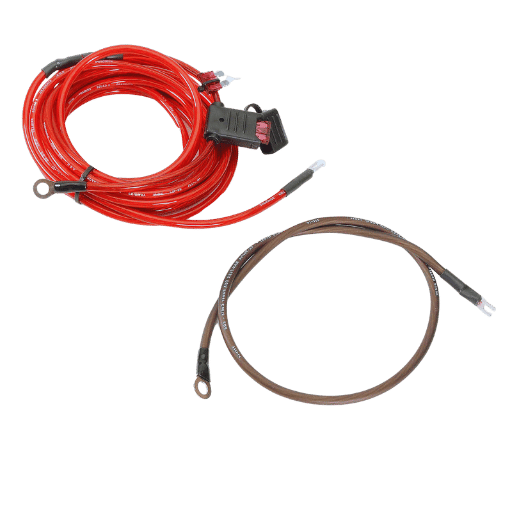
Ensuring Safe 12-Volt Wiring in Automotive Systems
Subpar design or installation practices for 12-volt automotive wiring systems can compromise their safety and efficiency. One key aspect of attention is choosing the correct wire size, which must correspond with the current draw and the acceptable limits of system voltage drop. For example, in automotive circuits, it is customary to keep the voltage drop under 3% to prevent system errors and reduced performance of the components involved. Determining the correct American Wire Gauge (AWG) based on current load and wire length is made easier with the use of wire gauge charts.
Equally important is the type of insulation used for the wires. GXL and TXL automotive grade wires, containing cross-linked polyethylene (XLPE) insulation, are specifically manufactured to cope with extreme challenges such as heat, oil, vibrating forces, and cutting abrasions. Compared to standard non-automotive PVC-insulated materials, these wires possess much more enhanced sturdiness.
It is just as important to ensure reliable grounding connections to eliminate the risk of intermittent performance of the circuits and electrical noise problems. The best practices for achieving optimal results include proper crimping as well as the use of good quality terminals and grounding points where metal-to-metal contact is essential for the grounds. Protecting the terminals from corrosion, moisture, and other harsh environments can be accomplished by using adhesive-lined heat-shrinking tubing.
Ultimately, routing and securing the wiring harnesses appropriately reduces the possibility of suffering mechanical damage. Examples of this include avoiding sharp edges, heat, or motion; additionally, using protective materials such as conduit or loom tubing. Following these principles will protect the wiring system and enhance the safety and reliability of the vehicle’s electrical systems.
Checklist for Safe and Efficient Electrical System Installation
Conduct a System Load Analysis
Evaluate the electrical load requirements of the system before installation. Estimate the power consumption of the system and check if the alternator and battery can suply them. For modern vehicles, remember to factor in the extra loads from the advanced electronics and safety features.
Choose the Correct Wire Size
Select wires that have the proper gauge rating based on the current load demand. For instance, a wire supporting a load of 20 amps should be no smaller than 12 AWG. Wires that are too small will overheat and can result in insulation melting and electrical fires.
Properly Ground the System
Secure all connections to the ground to ensure that voltage drops and noise problems do not arise. All points of contact for grounding wires must be free from dirt and corrosion and must be tightly bound. Multi-point grounding systems require careful design to avoid ground loops.
Choose Connectors and Terminals of the Highest Quality
Use connectors rated for the intended voltage and current level and preferably weatherproof. Preferable, connectors should be crimped as this ensures greater connection integrity than soldered fittings which can loosen due to vibration.
Protect Your Circuits with Fuses and Relays
Place the fuses as close to the power source as possible. Use relays to control high-current loads as they protect switches and lower the heat produced. Fuses should be selected according to the wire and load they are intended to carry.
Select Proper Insulation Materials
Use wires with exceptional heat and abrasion protective insulation in high movement and hot zones. For these applications, cross-linked polyethylene (XLPE) may be suitable.
Plan for Environmental Protection
The system design should ward off moisture, dust, and temperature changes. Use sealed connectors and grommets, and apply dielectric grease to terminal gaskets to prevent corrosive damage.
Follow Proper Routing Practices
Avoid high-heat zones, sharp surfaces, and moving parts when routing wires. Use grommets, clips, and cable ties to secure the wiring at measured intervals, taking care to avoid excess slack that could lead to wear.
Test After the System is Installed
Conduct multimeter continuity, voltage, and resistance checks on all the circuits. Estimate the voltage for the load to guarantee the system works as intended without any errors. Fix any issues detected right away.
Maintain the Industry Standards
Comply with ISO 6722 automotive wiring standards as well as the specific guidelines prescribed by the manufacturer. With proper traceability, the documented system can be easily diagnosed and troubleshot in the future through wiring diagrams and mapped components.
Frequently Asked Questions (FAQs)
Q: Why is choosing the correct 12-volt wiring size vital?
A: In the case of overheating, Choosing the correct 12 volt wiring size is important because it addresses containing the current load as well as fire hazards. Additionally, It reduces voltage drop which helps improve power delivery to your devices.
Q: How does the American Wire Gauge (AWG) system work when it comes to selecting the wire sizes?
A: American Wire Gauge is a system for arbitrary wire gage which assigns numbers to the diameter and cross-sectional area of electrical conductors. Gauges with smaller numbers have larger diameters which increases the amount of current (amps) that can be carried at 12 volts with minimal voltage drop.
Q: What are the criteria of a 12-volt system that require the size of the wire to increase?
A: Factors influencing the size of the wire needed for a 12-volt system include the distance the wire has to cover, the power supply with the amps rating of the equipment, and the allowable range of voltage drop. Higher length accompanied by higher amps requires larger wire size to ensure functionality and safety.
Q: What role does ampacity play in 12-volt wiring?
A: The meaning of ampacity is the load current a wire can safely carry. In a 12-volt system, understanding ampacity safeguards the wire’s ability to carry the current without overheating, protecting the wire, and the devices connected to it.
Q: What is the best method to compute the proper wire gauge for my 12-volt wiring project?
A: Using the calculator or chart specifically designed for 12v projects will simplify the computation for gauge size. In the case of 12-volt systems, a wire size calculator can be utilized, providing an efficient solution. It takes into account total amps, length of the cable, and permissible voltage drop.
Q: What is the recommended wire size for a 100-amp, 12-volt application?
A: When considering a 100 Amp load and a 12V supply, the wire gauge should not be thinner than 2 AWG or 1/0 AWG, based on the run length. Always consult a reliable 12 volt wiring size chart to ensure proper load and voltage drop considerations.
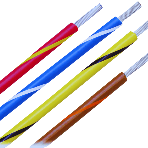
Q: How does stranded wire differ from solid wire in 12-volt wiring?
A: Stranded wire is made up of multiple smaller wires twisted with each other, after which it is insulated with a sheath. This complexity can provide an astonishing amount of flexibility and resistance to vibration, which is needed for automotive and marine applications. Solid wire, while stiffer, is often used in fixed installations. Both types have similar ampacity but differ in their handling.
Q: What is the impact of using an undersized wire in a low voltage system?
A: Many issues can arise while using undersized wire for a low voltage system. Increased resistance can lead to overheating in the wiring as well as the connected equipment, which would speed the equipment’s degradation and endanger lives. A system-wide loss of efficiency would occur. Always make sure wires are loaded liberally with size, in proportion, one might say, to the distance and run length.
- Q: In what way does the length of a wire run impact the size of the 12-volt wiring?
A: The length of the wire run impacts the voltage drop due to the wire’s inherent resistance. A longer wire run tends to increase the overall resistance which requires using a larger gauge wire to maintain safe voltage levels and system efficiency.
Reference Sources
1. Research and Design for the Power Hierarchy of a 160-Element Linear Towable Ocean Acoustic Coherent Hydrophone Array
- Authors: Max K Radermacher et al.
- Published: 2022
- Key Findings: This paper analyzes the design of a power supply system for a hydrophone array and includes the design considerations of wire gauge and power transmission for large distances. The research highlights the need for appropriate wire specifications to reduce the voltage drop across the wires.
- Methodology: The authors completed the research and design steps of the underwater power system along with detailed constituent component selection and schematic design, striving for reliability and cost-effectiveness (Radermacher et al., 2022, pp. 1–7).
2. A new device (FAQ.FIX®) for orthodontic bracket placement in straight wire technique
- Authors: Francesco Mazzeo et al.
- Published: 2013
- Key Findings: While not indirectly concerning wire diameter, this article analyses accuracy of placement which may have bearing where wire gauges are applied in orthodontics.
- Methodology: The research includes the construction of a prototype device that enhances the accuracy of bracket placement, an important step in orthodontic procedures (Mazzeo et al., 2013a, 2013b).
3. Application of Six Sigma Methodologies in Manufacturing of Automotive Wiring Harnesses
- Authors: Kamal Kamal and others
- Released: 2018
- Keywords: This paper investigates the application of Six Sigma methodologies in automotive wiring harness manufacturing, possibly concerning wire gauge calibration, measurements, and overall quality assurance.
- Research Approach: The authors applied principles of Six Sigma to streamline processes aimed at achieving lower defect rates and improved product quality within manufacturing activities(Kamal et al., 2018).
4. Voltage drop