Designing a solar power system encompasses various elements, and cable sizing deserves as much attention as the other elements. Adequate cable sizing is critical to the system’s safety, efficiency, and durability. Using a lower gauge will cause cable overheating, voltage drops, or a total failure of the solar setup while using a higher gauge would be an unnecessary expense. This guide aims to ensure that one’s system boasts of the appropriate cable size by possessing the correct set of tools and knowledge. This particular article, whether one is an installer or a DIYer, will suffice all the factors, formulas, and reasonable practices to ensure that our solar power system operates efficiently.
What Factors Affect Solar Cable Size?
Several elements will determine how one goes about charging the sizing of the solar cable. Among the most important ones are:
- Current (Amperage): The cable must be rated to withstand the highest possible current flow rate without overheating or incurring a drop in voltages.
- Voltage: High-voltage systems require cables fitted with more substantial insulation materials to prevent damage or safety concerns.
- Cable Length: Over longer cable runs, there is always more excellent resistance already present, meaning there is always an inevitable voltage drop. Using a larger cable size can help compensate for these losses.
- Temperature Ratings: The cable needs to handle the temperature of the surroundings without sacrificing performance and or safety.
- Regulatory Requirements: The Cable must comply with local electrical codes and standards to guarantee its safety and proper use for solar purposes.
Taking these into consideration will allow you to choose a specific cable size that will work to ensure desired efficiency while also meeting safety and compliance standards.
Understanding Solar Power and Its Requirements
Solar energy is obtained by converting solar radiation to electricity through photovoltaic (PV) panels or solar thermal systems. The invocation of solar energy systems necessitates the assessment of the appropriate site for adequate sunlight capture, along with the requirement for conversion inverter mechanisms, suitable panels with the desired energy conversion efficiency, and an appropriately designed system to maximize performance. Moreover, off-grid configurations or those requiring power storage for future use may require battery storage systems. Compliance with safety regulations and international standards is essential for maximum efficiency and system lifetime. Ensuring an effective maintenance strategy has long-lasting consequences on the efficiency and durability of the system.
The Role of Wire Gauge in Solar Installations
The selection of wire gauges is integral to the safety and functionality of solar systems. More wire gauge means more resistant wires; hence, less current would be carried. The system works more efficiently and minimizes energy loss and overheating, which can be caused by using wires from the wrong gauge. If cables were too big, costs would be unreasonably high, and on the contrary, if wires were limited in size, safety, and efficiency, it would pose a significant danger. For typical domestic setups, the amount of wire gauge would be determined by the expected current draw, distance of wire run, and working voltages. It is also possible to have more certainty in wire gauge complying with the National Electric Code (NEC) by consulting specialists for further assurance of proper system performance.
How Voltage Drop Influences Cable Selection
The voltage drop should be carefully analyzed when selecting a cable since it significantly influences the electric system’s functionality. When any specific current passes through a wire, a voltage reduction, known as voltage drop, occurs, which is induced whenever there is resistance in the conductor. Excessive voltage drop can cause equipment to fail to work correctly, resulting in energy loss and a safety risk. While selecting a cable, other factors like the cable length, current load, and the size of the conductor should also be taken into account to reduce the voltage drop as much as possible. Resisting the flow of electricity can be minimized by using a larger gauge cable, which can maintain the voltage at appropriate levels. Compliance with specific guidelines like the US national electrical codes aids in ensuring the efficiency and safety of the system.
How to Use a Solar Wire Size Calculator Effectively
Steps for Accurate Wire Size Calculation
- Ascertain the System’s Voltage: It is essential to identify and input the operating voltage of your solar power system, as this will assist in calculating the wire size.
- Determine Electrical Result: Find the current in amperes by dividing the total power output of your system in Watts by the voltage.
- Measure the Distance: Estimates should not be taken to calibrate for voltage drop; instead, the distance between solar panels and a charge controller or inverter should be measured accurately.
- Check Voltage Drop Guidelines: For reference, high tolerance rules for voltage drops, which are standard and range from 2 percent to 3 percent, are used.
- Use Calculators Specifically Designed For Estimating Wire Size: Input relevant data such as system voltage, current, and wire length into a credible wire size estimating calculator that meets the standards outlined by the NEC.
- Choose an Appropriate Wire Size: Based on the specifications determined by the calculator, reduce the resistance and get a wire gauge that complements your specifications.
- Check Compliance With Standards: The final step is ensuring that the installation adheres to the safety regulations set by the safety companies.
Common Mistakes in Wire Size Calculator Usage
- Input Data Errors: One of the endemic blunders is entering values like voltage, current, or wire length incorrectly or partially. Doing this may result in unsuitable wire size recommendations.
- Disregarding Voltage Drop: Inadequately considering voltage drop over extremely long wire lengths can lead to wire under-sizing, which can cause overheating and performance problems.
- Failure to Abide By NEC Norms: Failure to observe national electrical code norms may lead to the installation of devices that are not safe and compliant with the enacted legislation.
- Calculator Irrespective of Prestige: Non-standard calculators or non-ergonomic units can be inaccurate, so never trust them. Always ensure that the tool you are using applies accurate algorithms.
- Safety Margins Exclusion: For instance, ignoring future load increases and adjusting for environmental conditions may weaken and render the wiring system inoperative.
Tools and Apps for Solar Wire Size Calculation
The correct choice of solar wire size is crucial for safety and performance. Below are tested tools and apps to help in this undertaking:
- PV Watts Calculator (NREL): This tool is as excellent as the one developed by the National Renewable Energy Laboratory, as it offers excellent system modeling and wiring guidance suited for solar installations at no charge.
- SolarDesignTool Wire Size Calculator: A web-based tool that focuses on the precision of wire size calculations, factors in a voltage drop, and system parameters.
- Electrical Wiring Calculators ( Southwire ): These make wire sizing easy as they provide a blank form where the user gives vital information, followed by results.
- SolarEdge Designer: This is a professional tool with solar systems and includes wire sizing features as part of its solar system design features.
The tools above are used very often and are pretty simple to use, intuitive, and accurate in returning results based on user input. Proper use of tools while considering local codes will yield accurate calculations.
What is the Importance of Solar Panel Wiring?
Connecting the Solar Panels to the Inverter
One of the decisive steps in installing a photovoltaic (PV) system is the connection of solar panels to the inverter. The solar energy harnessed is turned into electricity through direct current (DC). It must be plugged into the inverter, which will then convert it into alternating current (AC) for household use or grid connection. For this reason, one needs to ensure that the positive and negative terminals are appropriately connected. Doing so requires caution to maintain proper wiring schematics and safety laws when connecting to a solar system.
The most common wiring configurations are series and parallel connections. A series connection permits an increase in voltage, such as that provided at the input of an inverter, while a parallel connection boosts the current. For example, suppose we have solar panels rated at 40 volts and ten amps. If we connect three panels in series, we should expect a voltage of 120V at 10A and 40V at 30A if the connection is parallel. Which of the two options you settle for depends on the entire system’s design or the inverter’s ratings.
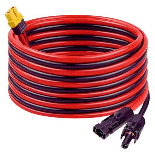
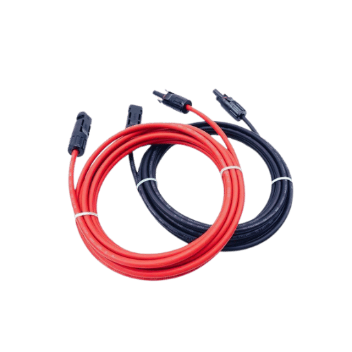
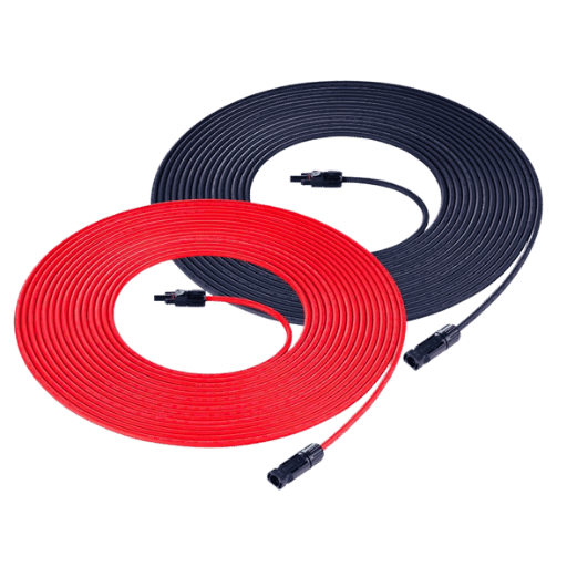
Similarly, It must also be remembered that the compilation of the solar panels with the inverter must be suitably grounded to protect it from electrical faults and surges. Robust and weather-resistant joints are best secured with solar cables and connectors like MC4 connectors, which are widely used. A fuse or circuit breaker must be installed to lessen the likelihood of overcurrent risks in the system.
Solar panel installation should follow safe practices and use the recommended tools. Local regulations must also be consulted to guarantee practicality and compliance with safety laws.
Types of Cable Used in Solar Panel Systems
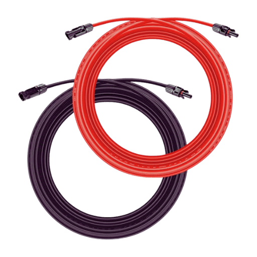
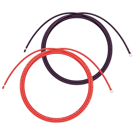
Solar panel systems depend primarily on two types of cables: PV cables and standard electrical cables. The former are custom-designed to meet the needs of solar operations, providing maximum protection against ultraviolet light, high levels of humidity, and temperature extremes. They are employed alongside standard electrical cables, such as AC cables cutting across the inverter and connecting it to the home or the grid, allowing solar panels to withstand outside exposure. If these cables are not appropriately selected, the system may be efficient, safe, and meet the necessary standards. However, it would undoubtedly result in noncompliance with the regulatory framework.
Ensuring Proper Voltage Drop Management
Managing the voltage drop is crucial in optimizing the performance of any electrical system, including solar systems. The sizing of cables should be done in such a way as to reduce the amount of voltage drop based on the total current and the length of the wires. Also, prominent conductors with lower resistance should be used for increased distances to minimize energy losses. Also, ensuring proper and good connections at all terminal points helps improve the system’s general efficiency—regular checks on cables and connections aid in sustaining reliable performance and adherence to safety regulations.
How to Determine the Right Wire Gauge for Your PV System
Calculating Amperage and Voltage Requirements
First, you must define the entire load your photovoltaic system must bear. This includes all the devices tethered to it and their respective wattage ratings. Then, using the following formula, you can calculate the amperage required by dividing the system’s watt value by its voltage.
Amperage (A) = Power (W) ÷ Voltage (V)
As an illustration, let us suppose the total power requirement is 1200 watts and the voltage of the system is 24, then the amperage required would be:
1,200 W ÷ 24 V = 50 A
This is important as it allows an engineer to estimate the amount of load and build appropriate equipment, such as cables and inverters, to manage the load safely. After that, manufacturer specifications and local electrical codes must always be verified to determine whether they meet the set requirements or are helpful to the system for compatibility.
Choosing Between Different AWG Sizes
When determining the appropriate American Wire Gauge (AWG) size for an electric system, the current rating, voltage drop, and wire length must be considered. AWG sizes are inversely proportional to the wire diameter and current capacity; for instance, a lower AWG number indicates a thicker wire with greater current capacity.
Ampacity is the term often used to describe the current capacity of a wire; this capacity largely depends on the metal used (usually copper or aluminum), the type of insulation used, and the surrounding temperature. For example, a 10 AWG copper wire can average 30 amps’ worth of ampacity under ordinary conditions, while a 12 AWG copper wire can reach 20 amps maximum. The longer the length of the wire, the greater the AWG size required, as a greater length will lead to increased resistance and voltage drop. Generally speaking, a voltage drop exceeding 3% should be avoided in most scenarios, as it may impact the performance.
For practical uses, consider the following example when deciding on the size of the AWG wires: however, for the same current over 100 feet, a 4 AWG wire may have to be used. If a system needs 50 amps over a distance of 50 feet, a 6 AWG copper wire will do to reduce voltage drop and for safety.
Always ensure you comply with the requirements of the local electrical codes and wire ampacity charts to avoid confusion and loss of confidence. Wire professionals properly realize these processes and steps while selecting the correct AWG size for the electric application to prevent overheating and energy loss.
Impact of Insulation on Wire Performance
Wire insulation is essential for performance by preventing electricity leakage, short circuit risks, and external threats like moisture, heat, or chemicals. The type and quality of the insulation used significantly affect the wire’s durability and safety in operation. PVC or XLPE are common insulating materials based on voltage, temperature, and environmental conditions. If done correctly, insulation increases efficiency, adheres to safety standards, and extends the life of the entire electrical system.
How Does Solar Energy Influence Cable Size Requirements?
The Impact of Solar Array Size on Cable Selection
First, the multifaceted elements of the solar array, including its size and load, are considered when selecting the appropriate cable size for the solar system. Higher capacities would require multistranded copper wires for efficient and safe energy transfer. The wire’s current-carrying capacity can account for a greater length, reducing voltage transmission loss. By assessing such elements, I guarantee that a balance between safety and light output is achieved while enhancing the solar system’s performance.
Adjusting Cable Size for Off-Grid Solar Systems
In the case of off-grid assemblies, I evaluate the energy requirements of the equipment to be connected and the distance between the components, as these factors strongly affect the cable sizing and interconnection. Since off-grid systems usually need longer cables to interconnect batteries, charge controllers, and solar panels, I use wires and cables with higher currents to decrease the voltage drop across them and increase the system’s efficiency. Moreover, I also consider the off-grid configurations that usually tend to have high current loads. To ensure that the cables are approved for safety and reliability, adequate current ratings are allocated. In doing so, I take care of this maxim, and requirements for one functioning do not only exist but are satisfied in the context of Off Grid installations.
Evaluating Maximum Current in Solar Installations
To determine the parameters for the maximum current of the solar installations, I evaluate the total operating current of all the components in their peak operating mode. This includes measuring the system’s rated maximum power and dividing it by operational voltage while factoring in efficiency figures and temperature. I also assess manufacturer guidelines associated with the elements to avoid the risk of overcurrent. In a sequence of related calculations and parameter checks described above, I have determined the maximum current and have appropriately picked cables, fuses, and other protective apparatus necessary for safely operating the system.
Frequently Asked Questions (FAQs)
Q: What should I consider when determining the size of the solar DC cables?
A: Some of the things that should be considered are the current capacity, the loss of voltage, the length of the cable utilized, the range of temperature, and lastly, the configuration of the solar power system. These factors significantly transmit electric current via cables and reduce energy waste throughout the solar project.
Q: How does the distance from solar panels to the charge controller influence the wire diameter required?
A: The distance from the solar panels to the charge controller is crucial for the cable layout. To reduce voltage drop, larger wire diameters are needed for longer distances. Depending on the length of the solar DC cables, the voltage drop calculator can be used to gauge the thickness of the wire.
Q: Why is proper wire sizing critical in a solar power system?
A: Proper wire sizing is essential to enhancing the system’s performance. It aids in power transfer, energy loss, and overheating. If the cables are more miniature than necessary, there is a reasonable expectation of a voltage drop, which will cause poor performance. In comparison, larger cables than necessary will raise expenses for no reason.
Q: What methods can I use to figure out the amp capacity of my solar cables?
A: Start by analyzing both the maximum current output and the input of the solar charge controller for your solar panels. Now, for the sake of safety, add an extra 25% to the amp capacity. This will ensure that you have enough cable capacity to handle any load comfortably in the future.
Q: If I compare DC-sizing solar cables to AC-sizing, what are the main distinctions between the two?
A: The main difference in sizing solar cables for DC and AC is the voltage and current characteristics. For example, DC cables usually carry a large amount of current at a low voltage, meaning larger wire diameters are necessary to connect effectively to a solar battery bank. AC cables within solar systems usually carry less current but at a higher voltage. The solar array’s output generally measures DC cables, whereas the power of the Inverter measures AC cables.
Q: What cable length are solar panels’ circuits, and how does temperature affect these cables?
A: Temperature has a very crucial impact on the sizing of solar cables. Specifically, high ambient temperature diminishes a cable’s current-carrying capacity; therefore, larger wire diameters would be required for your solar project. For solar cable size, consider the hottest temperature you expect in your region and include appropriate derating modifications to carry the electrical current under all conditions.
Q: What wires are suitable for connecting the solar panels to the charge controller?
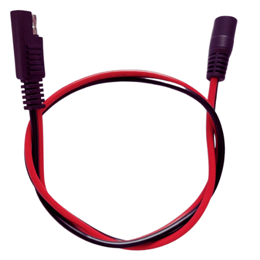
A: Copper cables manufactured for solar PV systems must connect the solar panels to the charge controller. Such wires should have a UV-resistant SDPE outer jacket and be prepared for outdoor use. Standard wire types commonly found in solar systems are PV Wire, USE-2, and THWN-2. The cable type varies depending on the area’s electrical codes and the design of the off-grid solar power system deployed in the region.
Q: How can I determine the correct wire size using American Wire Gauge (AWG)?
A: First, determine the number of amps needed and the maximum voltage drop for the solar system to calculate the correct wire size using American Wire Gauge (AWG). After this, refer to the AWG chart, which indicates the amount of current each wire gauge can carry and the resistance of one foot for each wire gauge. Generally, select the largest wire that meets your requirements, but remember that the lower the AWG number, the larger the wire’s diameter.
Reference Sources
1. (Mosheer, 2016) “Optimal Solar Cable Selection For Grid-Connected Photovoltaic Systems”
- Published in 2016
- The article discusses determining the optimal capacity of solar cables for grid-connected solar PV plants. The method optimizes the investment cost of solar cables and the cost of losses over their technical life.
- The key findings illustrate that solar cable sizing is critical to minimizing PV systems’ losses and creating long-term savings. In the economic assessment of PV systems, the temporal resolution of solar radiation data is also critical for selecting the optimal solar cable size.
2. (Desai et al., 2020, pp. 2397–2402) “Stimuli impact relating to temperature on the drop in the DC cable voltage in solar grids which are utility based.”
- Published in 2020
- This study investigates the relationship between temperature increase and decrease in voltage for a 250 kW solar PV system for DC cables used in solar systems. Empirical modeled approaches were developed to determine the criteria complication arising from the voltage drop due to temperature.
- The key findings reveal that when the DC cable is installed outside in an environment with temperatures over 30 to 35 degrees Celsius, there is a 12 to 18 percent increase compared to the formal test conditions with temperatures above 40 degrees Celsius. Choosing the proper cable size can save 2400 kWh to 5400 kWh annually, reduce CO2 emissions by 1200 kg to 3000 kg, and reduce coal consumption by 300 kg to 700 kg annually.
3. (Høyer-Hansen et al., 2022) “Optimisation of power cable ampacity in offshore wind farm applications”
- Published in 2022
- It has been noted in this paper that FEM is applied to ascertain the ampacity of a three-core HV cable which is mounted in a J-tube of an offshore wind farm. This paper also adds that when the direction of solar influx is considered, the maximum temperature is higher than the permissible temperature of the cable core, which is not the case when considering steady state only.
- When the heat transfer coefficient is modified to reflect higher wind velocities at the 20m/sec envelope during peak power production, the highest core cable temperature is lower by 18 degrees Celsius. These calculations can be easily translated into practice by raising the allowable current through the cable and then decreasing it by 17% or reducing the cable’s cross-sectional area.
4. Get Your Solar Cable Needs Covered with JOCA – Your Trusted Supplier