A critical yet minimizable consideration while planning a solar power system is choosing the appropriate cable size, which significantly impacts efficiency, safety, and performance. Considerations regarding wire gauges become even more important when connecting a 100W solar panel due to the probability of severe power loss or becoming detrimental to user safety. This document is meant to assist you in every possible way in understanding the intricacies of wire sizing for a hundred-watt solar panel. What is allowed and not allowed and why will be elaborated by breaking up ampacity, voltage drop, distance, and load requirements. Whether it is your first time coming into contact with solar energy or improving an existing setup, this document will surely ease the complexity.
Why is choosing the right cable size important for a 100W solar panel?
Selecting the right cable cross-section for a 100W solar panel serves the important purpose of ensuring the efficiency, safety, and longevity of the system. The correct cable sizing greatly reduces energy losses resulting from resistance and concerns with steady voltages and avoids overheating, which can cause damage or present safety issues. Using smaller cables may incur extensive power losses and damage the system, whereas larger ones will only serve to raise the expenses without any justification. Cables for the currents supplied by the panel for the gauge conduits connecting the charge controller or battery should be selected, and this will also provide the greatest reliability.
How does wire size affect solar panel efficiency?
The size of a wire can affect the efficiency of a solar panel as it determines the circuit’s resistance. An oversized wire increases resistance, which leads to a higher loss of heat energy and thus reduces the total power delivered to the system. On the other hand, the choice and correct sizing of the wire reduces the resistances, ensuring that it is efficient enough to transfer energy from the solar panels to compatible devices such as the charge controller, battery, or inverter. When the wires are properly sized, there are no unnecessary losses in energy while maintaining system reliability and performance.
What are the risks of using undersized cables?
There are several critical implications of using cables that are too undersized, for example:
- Overheats – Such cables have a higher electrical resistance, which translates to generating heat, and an extended time in heat standing threatens to damage the cable’s insulation, which becomes a potential fire hazard.
- Voltage Drops – Too small a cable diameter introduces considerable voltage loss, which affects mobile and PST solar panel systems, for example.
- System Failures – Too high heat and worse off voltage in solar panel wire can cause parts to have a shorter lifespan, to say the least, and that decreases the reliability of the entire system.
- Safety Hazards – Because of damaged cables or overly hot wires, the risk of electric shock and fire increases, and that is, needless to say, not good for the property and safety.
These risks can be avoided by ensuring the correct diameter cable is used so that efficient and safe operations can be conducted whilst maintaining guarantees on wires for instance.
Can oversized cables impact solar panel performance?
Oversized cables in a solar panel system have some advantages as well as some disadvantages, depending upon the circumstances. Furthermore, oversized cables transfer lower electric resistance, which reduces the voltage drop incurred over longer lengths of cables. This is beneficial in some applications, particularly in those where the cable runs are long and the aim is to enhance the efficiency of power transfer from a solar panel to an inverter or a charge controller. Cable threads are reduced to less than 2%, at which point they can be considered reasonable, but larger cables reduce this even further and improve the performance of the cable.
On the other hand, there are some drawbacks to these oversized cables. First, larger cable sizes are heavier, making them more difficult to work with during installation, and most importantly, they cost more due to added materials. All these factors seem to affect the small solar system performance but do not affect them directly, so for smaller residential solar systems employing standard cable sizes, these factors seem irrelevant. As outlined in technical guidelines such as those provided by the National Electric Code (NEC), observers for the best performance and cost-effective measures should check if the cable sizing is appropriate for the current carrying capacity and the length of the run.
In conclusion, I would like to say that oversized cables do not negatively impact solar panel power output; however, their application needs to be evaluated so that unnecessary complications and costs are not incurred to attain higher efficiency. Systems are designed to provide optimal cable sizes for the particular current, voltage, and distances.
How to determine the correct wire size for a 100W solar panel?
What factors influence cable size selection?
I consider several important aspects to determine the correct cable size for a 100W solar panel. First, I analyze the current output of the panel since a larger current necessitates thicker cables to reduce resistance, which helps prevent the controller from overheating the battery connection. Secondly, the distance from the panel to the charge controller or battery is considered – long distances also need bigger cables to decrease the voltage drop. Lastly, I ensure the selected cable suits the system voltage level and meets operational safety norms and regulations. These considerations help me choose the most efficient and safe option.
How do you calculate the amperage of a 100W solar panel?
To calculate the amperage of a 100W solar panel, I divide the panel’s wattage by the system’s voltage. For instance, if the panel operates at 12V, I use the formula Amps = Watts / Volts. This means 100W divided by 12V equals approximately 8.33A. This calculation helps determine the current output of the panel under optimal conditions.
What role does voltage drop play in wire sizing?
The appropriate wire size ensures that the voltage drop is kept to a minimum, thus preventing degradation of the performance level. Excessive drops could cause wires to overheat, damaging the equipment. Therefore, performance decline is taken into account when choosing wire size, propelled by the significance of the connected equipment. Performing the necessary calculations and understanding the importance of the wire length and voltage drop help preserve the electrical systems’ efficiency and safety.
What is the recommended cable gauge for a 100W solar panel?
Is 10 AWG wire suitable for a 100W solar panel?
Yes, the wire gauge can be adjusted accordingly, but it can be said that a standardization-blessed 10 AWG wire is adequate to carry the current from a 100 W solar panel. However, this is subject to certain conditions, such as the specific wire length, voltage, and current. A normal 100 W solar panel can be expected to output an optimal current of approximately 5.5 amps and scale over an operating voltage of around minus 18 volts.
As defined in the AWG standards, a wire gauge of ten can be expected to output or support a maximum current exceeding 30 amps, which will be more than enough to support power generation from a 100-watt panel supplying around 5.5 Amps of continuous load. It is a known fact that for low voltage systems such as solar systems, having maximum efficiency with lower voltage drop becomes paramount. With the appropriate wire type and size, such as 10 AWG wire, there is an improvement in the impedance and overall wire resistance, which gives us an improved voltage drop over the distance covered. For instance, if the wires were extended over a distance of 20 feet, a change of 2 % in voltage drop could be observed which would ensure that the panel maintains optimal operating conditions.
For wire lengths exceeding 20-25 feet, let me rephrase it, the more the wire stretches the more thickness it loses, so calculations should be made accordingly this can ensure that the voltage drop remains 3% or below. On the other hand, if the wire is particularly long, then it is advisable to run an 8AWG or 6AWG wire in order to lower resistance levels and improve efficiency. When it comes to selecting the appropriate wire gauge, it is always important to bear in mind the requirements of solar panel systems, such as maximum current and total wire stretch length.
When should you consider using 12 AWG wire?
Because of its excellent current carrying capacity and flexibility, 12 AWG solar wire is widely utilized in solar installations and other electrical equipment. This gauge is satisfactory for circuits carrying up to 20 amps under most situations; therefore, it can be employed for low or moderate electrical loads. Furthermore, 12 AWG wire can support approximately 50-60 feet while sustaining a voltage drop of less than 3%, depending on the system voltage, such as 12V, 24V, or even 48V DC.
In the case of solar panel systems, it is reasonable to use 12 AWG wires if the current for the complete system will not be above this limit as long as the length of the wire stays within the suitable range for conserving energy. Most suitable for tiny off-grid solar systems such as RVs, boats, or residential applications that tend to have low power requirements.
We are centered towards not destroying the electronics, for which the equipment is not to be used in extreme conditions – Say from 60 Celsius to plus 120 Degrees Celsius while following the recommendation that the National Electric Code (NEC) provides when using the 12 AWG wire by recommending the consideration of insulation rating (e.g., THHN, PV wire, etc.), ambient temperature corrections, and conduit fill limits. For instance, in lower temperatures, a 12 AWG wire with 90°C insulation should only work under 25 amps for normal circumstances, and if the wire is deployed in continuous usage, further NEC guidelines are advised for –derating based on temperature and other factors- So Always consult an electrical engineer or stick to the local code requirements to find the right gage for your application.
How does cable length affect the choice of wire gauge?
The length of the wire also determines the appropriate wire gauge to use in an electrical circuit because of voltage drop. Whenever the electrical current flowing in a wire is opposed to the load the wire supplies, there is a drop in voltage. This is often referred to as the longer the run of cable in a DIY solar system, the higher the resistance, and as a result, the voltage drop increases. Also, the DIY solar system setup gets easier to do. In most cases, a voltage drop of less than 3% is a widely accepted value for optimal and dependable load performance.
When determining the wire gauge to use, the length of the wire, amperes load, and volume of the system are considered. For instance, a 12 AWG wire might be adequate for a 120 volts 20 amps load applied across 50 feet. If a 20 amp load is moved further back by an additional 100 feet to 150 feet, one may need to use rods with a higher thickness rating or 10 AWG to limit voltage drop to an acceptable number.
Calculating the voltage drop can be combined with other methods to simplify the assessment of the dependence between the length of a wire and its gauge. As an example, the voltage drop is given by the equation:
Voltage Drop = (2 × Length × Current × Resistance) / 1000
Values for the current resistance for several wire types are found on electrical reference tables. Moreover, it is important to confirm these values and determine a wire length that will allow the gauge selected to practically satisfy the energy needs of the load without incurring large costs in energy loss. As mentioned before, equipment that does not consider cable length may produce and consume a lot of energy or even cause the wire to overheat and become a fire risk. Also, note that the calculations must match NEC regulations or standards from the local region to ensure safety.
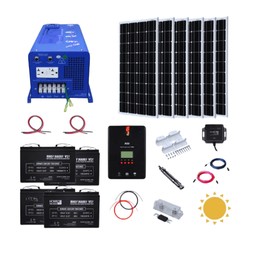
How does the solar charge controller impact wire size selection?
Do MPPT and PWM controllers require different wire sizes?
The type of solar charge controller, either MPPT or PWM, affects the wire size selection. These two types of controllers operate distinctly differently and influence the amount of electrical current in a system and, consequently, the amount of wire needed for the system.
Powerpoint trackers increase the power output of solar panels by directly changing the input voltage to the maximum power point. This improvement in efficiency results in greater operating voltages and lower operating currents than is common with PWM controllers for the same power output. The wire used must carry maximum current; therefore, systems with MPPT controllers can be designed with lighter gauge wires. However, other considerations like voltage drops and international standards must be considered while selecting wire sizes. For instance, if an MPPT system operates at 48 volts but lowers current to around ten amps, it can be compared with a similar PWM system designed to work on 12 volts at a 40 amp range – both systems, therefore, have quite distinct current flows.
In other words, PWM controllers found in some solar systems transfer the power from the solar panels by adjusting the panel voltage to the battery voltage. For this reason, a high current load may be required, especially in low-voltage systems. Such higher currents typically require larger gauge AWG solar wires in order to reduce the voltage drop that will otherwise be very unsafe. For example, a PWM-controlled system may require a 6 AWG wire, considering realistic distances and configuration, although a 10 AWG wire would suffice on the same system with an MPPT controller and different distances and loads.
Determining wire size is a complex process in which the system voltage, current, and cable length are evaluated to determine the correct wire size within allowable limits and the appropriate codes, generally the NEC. An MPPT controller would accommodate higher system voltages than an MPPT controller, so it can often provide design flexibility in lower wire sizes. The treatment is uniform and revolves around assumptions and estimates that cover most of the system configuration simultaneously.
What size wire should you use from the controller to the battery?
Ensuring the correct wire size for the connection that joins the charge controller to the battery bank is imperative in maintaining safety, effectiveness, and adherence to electrical regulations. Since multiple factors influence the amount of total current, permissible voltage drop, and cable length, the correct wire size depends on them.
Systems are said to perform quite well with a 3% maximum recommended voltage drop, which also, in some instances, is said to improve system effectiveness by being reduced to 2% or lower. For example, it can be noted that a 3% voltage drop in a 12V system would give a negative 0.36V and that wiring should be suited to ensure the drop doesn’t exceed this value over the given cable length.
As a point of comparison, the American Wire Gauge (AWG) chart offers wire sizing standards for certain current ratings and distances. For example, When a system takes 30 amps and has a total round-trip distance of 10 feet, 10 AWG wires might provide satisfactory results.
- For a 20-foot round trip, an 8 AWG wire would be the best option.
- As for a 15-foot round trip using 50 amps, a 6 AWG wire would give steady results.
Because wires might generate heat, using wires that are not too small is vital. Too small wires can lead to overheating, lower efficiency, and an increased risk of fires. When determining the wire size, it is also important to follow the NEC regulations, which state that factors like temperature and being bundled with other cables may require some electrical power reduction.
In other circumstances, even though using a larger wire can be expensive, it will increase a system’s reliability in the long run and minimize voltage loss. Voltage loss can be determined using many online voltage loss calculators and NEC tables, which provide more than enough information and assistance when sizing electrical wires for a specified system. Always comply with the local electrical code and contact a licensed electrician if uncertain.
Are there different wire size requirements for 12V vs. 24V solar panel systems?
How does system voltage affect wire gauge selection?
System voltage is critical in selecting the appropriate wire gauge for any given solar system. For example, when comparing different wiring systems, high-voltage solar systems such as 24V or 48V have a finer wire gauge than their 12V low-voltage systems about distance and amperage. This is because a higher voltage induces a lower current (Power = Voltage × Current), a lower current implies smaller energy losses caused by the wiring, and lower energy losses caused by the wiring, in turn, eliminate excessive voltage drop, which in turn has a greater impact on large solar systems.
Going back to the pole example, if we plant our poles and string a wire for a vertical distance of 50 feet using a 12V wire and pump a 10Amps current, we will find that our cable has a voltage drop of 3% between the poles when using a ten a 12 AWG wire. However, if we find ourselves outside the 50-foot vertical space and so were able to pump out a 24V with 10 Amps, the current would only have been 5 A. This sets positions where we may then be able to increase the radius on the otherwise 12 AWG wire. In short, the previous example captures the effectiveness and economic benefit of higher voltage systems.
However, it is critical to determine the wire size based on factors such as load current, system voltage, weight conductor materials (Copper or aluminum), and distance. Remember to use appropriate instructions such as NEC Ampacity Tables and Voltage Drop calculators for the purpose at hand. Also, always be sure that your design meets the relevant electrical codes and standards.
Can you use the same wire size for 12V and 24V panels?
No, the reason for this is because a 12V panel draws more current as compared to a 24V panel, thus the panels will have to use different wire sizes. With larger voltage panels, less heat is produced as the current is lower, thus ultimately a 12V panel would work properly with a wire larger in size than used by a 24V panel if the undersized wire gets too hot. To ensure safe and efficient operation, you must select a wire size that matches the specific voltage and current requirements of your system. Referring to NEC ampacity tables and performing accurate voltage drop calculations are imperative for selecting the right wire size for different voltage configurations.
What are the best practices for wiring a 100W solar panel system?
How do you minimize power loss in your solar wiring?
For efficient working, which does not incur losses, it is necessary to have high-quality copper wires as they reduce voltage drop, selecting seals to ensure lowered resistance. It’s important to follow this guideline as it ensures Essel always has efficient solar panel wiring that prevents overheating and short-circuiting. As mentioned before, powering down solar panels at a longer distance can limit wire runs, creating resistance. This unnecessary resistance forms energy leaks and causes corrosion, which can be easily avoided by insulation combined with good-quality connections and seals. All of these practices can be incorporated by isolating and blending simultaneously using seals and wires. To ensure a more reliable feel and quality, ensuring all connections and wires serves an important purpose: increasing efficiency.
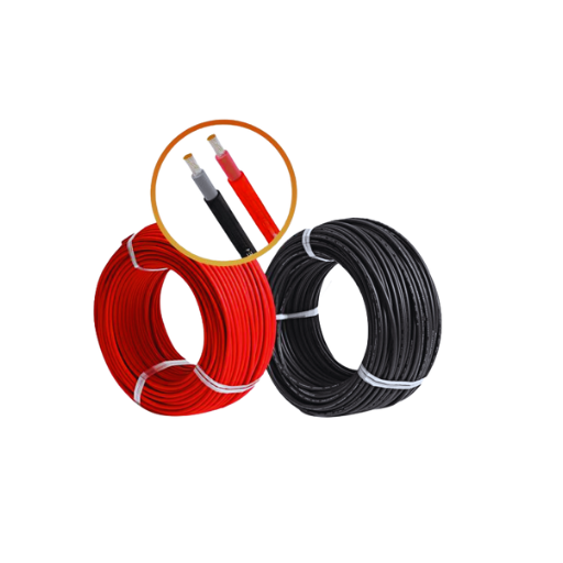
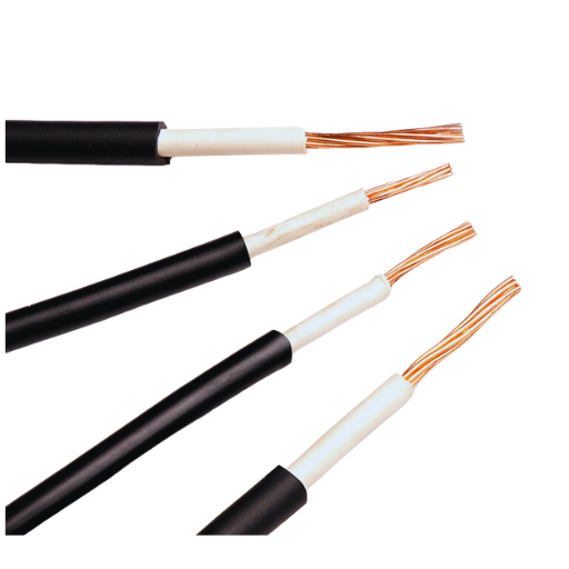
What type of cable is best for solar panel installations?
In order for solar panels to fully perform and emit the best output, they should be connected to wires or cables that are UV resistant, copper insulated, and designed for outdoor usage, like USE-2 wires or PV wires. Wires of this type are designed to uphold harsh climatic conditions and provide proper conduction for extended periods. For installation of systems that rely on grounding, the PV wires are deemed sufficient as they have extra insulation wrapped around them to withstand higher voltage and increased durability. Always ensure the wire you use is safe because it complies with electrical codes and standards in your local area and is compatible with your solar system.
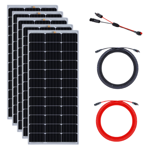
How can multiple 100W panels be adequately connected in series or parallel?
When connecting multiple 100W solar panels, both series and parallel configurations have advantages, depending on your system’s application and electrical requirements.
Series Connection
In a series connection, the positive terminal of any panel is linked with the negative terminal of the subsequent panel. This configuration raises the total voltage of the system while keeping the current equal to one panel of the same type. For instance, connecting three 100W solar panels with the voltage and current ratings of 18V and 5.56A, respectively, would result in a total system voltage of 54V [18*3] while the current remains at 5.56A. Systems that operate at higher voltage levels are more effective in reducing voltage drops when deployed over considerable cable lengths, and larger cables are necessary. Such high voltage levels systems are suited for specific controllers and inverters. For instance, MPPT controllers depend on higher input voltage levels to determine output efficiency.
Parallel Connection
In a parallel connection, the positive terminals of the panels are joined together as one common positive terminal, and all negative terminals are joined together as one similar negative terminal. This arrangement does not affect the system’s voltage in contrast with control in the present amount. For example, suppose three 100W panels in parallel are connected. In that case, the total current is 16.68A or 5.56A x 3 of current to 18V, so the required voltage to the battery, container, and controller is 6. 6. In the case of the connection in question, a parallel connection is preferable for systems with devices or charge controllers which operate at low voltage but require a higher current to work.
Considerations for Series and Parallel
Cable SizingFor series configurations, thinner cables can be used since the current remains unchanged, reducing costs and losses in different solar systems. For parallel configurations, thicker cables may be required to handle the increased current safely.
System Safety: Properly rated fuses or circuit breakers must be installed during such connections to avoid damages caused by exceeding the rated current amperage.
Shading Effects: A solar panel’s efficiency is hindered if a single panel of the series arrangement gets shaded. The Center has a program, and bypass diodes are needed as well. The Alled solar shading systems are not directly affected, but installing blocking diodes to prevent reverse currents is also essential. Parallel systems are less affected because blocking diodes’ use is advocated.
Compatibility: Attention is required to ascertain that the self-inverter or charge controller to be used is compatible with the current drawn by the configuration.
Designing or configuring the array is sufficient to achieve optimum performance and high reliability while meeting applicable electrical codes, ensuring long-term reliability. In the end, choosing a series configuration, a parallel one, or a hybrid configuration that incorporates the two will depend on your system’s voltage amperage and environment settings.
Frequently Asked Questions (FAQs)
Q: What size cable should I use for a 100W solar panel?
A: A rule of thumb when using a 100W solar panel is to use a 10AWG cable because it would blemish most uses. But things like wire run lengths, system voltages, and currents can change that. For small distances on a 12V system, for example, a 10AWG wire will do just fine. On the other hand, if you need the wire to run long distances or even plan to hook up another panel, then it could be wise to go for an 8AWG cable instead.
Q: How does a wire gauge affect a solar panel’s performance?
A: The performance of solar panels in a solar power device is also greatly dependent on the use of wires. Currently, most solar panels operate best with heavier wires (smaller gauge) in place. Lowering the circuit resistance reduces the voltage drop, and power loss is minimized, especially at longer distances. Using the right gauge wire is essential for the solar power system to operate efficiently. This ensures maximum energy transfer from the solar panels to a 12V battery or an MPPT controller.
Q: May I use the same gauge of wire when connecting different solar panels in a series circuit?
A: When wires are used to connect panels in series, Gursky contends that they must only be of the same gauge as required for a single solar panel wire because the current remains static, and only the voltage increases. However, ensure the wire voltage rating is suitable for a series connection. Always consult the specifications for your solar setup for additional information, such as a multiplier or number of panels and total system voltage rated, to select the most appropriate wire gauge.
Q: Which parameters affect the cable size in a solar panel installation?
A: There are several factors to consider when deciding the cable size for solar panels: 1. Current (amps) supplied by the panel 2. Physical distance from the panel to the connection point, 3. The system’s voltage (12 volts, 24 volts, etc.) 4. The surrounding temperature can have extreme negative effects on the solar panel wire. 5. plans for expanding the system 6. Laws and regulations on electrical activities that govern the area These variables should be considered to meet the desired size cable for the type of solar power system planned.
Q: Is there a difference between a solar cable and a regular electrical wire?
A: There is a difference, indeed. Solar cables are intended solely for photovoltaic installations. Hence, they offer benefits such as: 1. Insulation resistant to ultraviolet rays for outdoor applications 2. Elevated temperature tolerance 3. Improved flexibility for enhanced fastening 4. Tinned copper conductors for improved resistance to corrosion. Regular electric wires may be appropriate for some indoor parts. However, they should be avoided when connecting solar panels, charge controllers, and batteries in the solar arrangement.
Q: What is the method for determining the ideal wire size for a solar panel with a 100W power output?
A: The ideal wire gauge for a 100-watt solar panel can be determined as follows: 1. Determine the current capacity of the panel by amps ( for instance, 6-8 amps is what most 100W panels can output). 2. Measure the distance between the solar panel and the charge controller. 3. Select an appropriate voltage drop between 2-3 percent. 4. Look for an online cable size estimator or refer to wire ampacity charts. 5. The maximum cable size for a 100W system operating on 12v is around 10 AWG and is fit for short runs or small systems. Still, if the system is to be expanded, it would be better to have 8 AWG or thicker cables for larger systems or longer cables.
Q: For a standard 100W solar panel, how suitable is a 6mm cable?
A: Normally, one would expect a 100W solar panel to operate between 6-8 amps. And with these numbers, we can say that using a 6mm cable or around 10 AWG is a viable option. However, thicker options such as 8 AWG (8mm) can be a smart pick for those with a considerably longer cable run or who want to scale their system in the future.
Reference Sources
1. Headings: A Development of an Efficient Analog PWM Solar Charge Controller for Stand Alone Solar Photovoltaic Systems: Freestyle Current Mode
- Authors: : M. Islam
- Year Published: 2021-10-01
- Highlights: This research is useful for the design of a solar home system comprising a solar panel, a lead acid battery, and a PWM solar charge controller. It recommends the correct sizing of system components, such as cables, to serve the purpose of energy transfer under the solar system. The research provides a technique for analog PWM solar charging, which has never been done before. In contrast, some critical limiting factors, such as cable length resistance and internal resistance of a battery, which are the main codes for cable size for a solar panel system, were considered (Islam, 2021).
2. Title: A Studio’s Off-Grid Solar Energy System: Designing Requirements
- Authors: Waqas Ali et al
- Publication Date: November 1, 2018
- Summary: The study gives insights regarding off-grid solar energy system design requirements, including sizing PV panels, charge controllers, and cables. It inspects the technical details required for the evaluation of load energy requirements. It explains the relevant components in the analysis and design of the system, such as cable sizing to decrease energy losses and improve the system’s efficiency (Ali et al., 2018, pp. 1-6).
3. Title: Prototype for Solar PV-Battery Hybrid System
- Authors: A. W. Xu et al.
- Publication Date: 2020-09-28
- Summary: This study prototype targets the issues in designing and constructing a solar PV-battery hybrid plant. It points out the occurrence of LIMITATION cables in solar panel electric production, functioning as a determining element in energy sizing to assure system efficiency(Hendriana et al., 2020).
Research methodologies and summaries
- Companies need to focus on elements such as cable imperatives because, as all articles under review insist, cable sizing is also of utmost importance for solar panel systems. Cable dimensioning aims to eliminate resistive losses, minimize energy transfer inefficiencies, and ensure system reliability in all operational modes.
- The papers assist in all manner of design by calculating cable length and resistance and explaining how these parameters influence the system’s performance parameters. All the works offer methodologies for estimating cable size for specific characteristics of a solar panel and the load.
- It helps improve the power models that some studies have done quite accurately and correlate estimates of cable sizing with actual cables on real panels in actual situations.
Get Your Solar Cable Needs Covered with JOCA – Your Trusted Supplier