The nature of the required electric work calls for selecting the appropriate cable size to maintain safety, efficiency, and regulation compliance whenever necessary. “Is it possible for a six mm² cable to operate under a 40-amp load?” This was the most popular question among the company’s Independent Electrical Contractors and handypersons. This is not a simple query and requires a thorough analysis as other elements such as cable insulation type, installation method, ambient temperature, and even the circuit’s length all bear material considerations in assessing the ampacity of a wire. Throughout this article, we will be going through the necessary standards that help answer this query with specificity, including, but not limited to, damp devisakaan volt drop, which should be observed in the process. In particular, wire size and cable load capacity for your unique application will be discussed so that you can make an informed decision.
What is the Current Carrying Capacity of a 6mm Twin and Earth Cable?
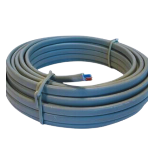
Depending on the installation method and conditions, a 6mm twin and earth cable can vary in operating current. For example, when clipped directly and assuming an ambient temperature of 30 degrees, the cable’s operational current is approximately 47 amps. However, this value can decrease due to insulation type, multiple cable grouping, higher ambient temperature, etc. Always check with the local standards or wiring regulations to be within the installation requirements.
Factors Affecting the Current Carrying Capacity.
- Ambient Temperature: Increased temperature diminishes the cables’ ability to cool, decreasing the amount of current the wires can carry.
- Cable Insulation Material: Insulating materials with lower thermal resistance will not allow for higher currents to be carried.
- Cable Grouping: Retaining cables together reduces the redistribution of heat and thus requires derating to avoid overheating.
- Installation Method: Heat loss in the case of ducts and walls is different than in the case of open-air cable installations, which changes the capacity.
- Conductor Material: When held at the same size, copper cables are observed to hold more current than disadvantageous aluminum regarding conductivity.
These factors must be carefully evaluated against applicable electrical standards to ensure safe and efficient cable operation.
Comparing 6mm vs. 10mm Cable for 40 Amp Loads
When the load to be connected is 40 Amps (guideline recommends), a 10mm cable can be considered safer than a 6 mm. That said, while a 6 mm cable can supply 40 Amps under certain conditions, it implies being rather close to its rated limit and with increased resistance, either due to poor wiring or environmental reasons, it would readily overheat. In contrast, a 10 mm cable provides ample safety margins from overheating and has lower voltage drops and higher efficiencies, more so at longer distances. Always seek professional advice to ensure compliance with electrical standards by reviewing the local regulations and the like.
How Voltage Drop Impacts Capacity
Voltage drop is an important aspect that influences the electrical system’s capabilities and effectiveness. It is caused by the flow of electric current through a conductor, which results in the difference in voltage between the source of power and the point of usage. The material of the conductor also determines this phenomenon: the current carrying cross-sectional area of the conductor, the length of the conductor, and the current being transmitted.
High voltage drops could cause failure or even some physical damage to the equipment due to high energy consumption or decreased energy efficiency. For example, the NEC (National Electrical Code) dictates that the drop in voltage in branch circuits should not be more than 3% and that the total circuit, including feeders, should not be more than 5%. To compensate for the voltage drop, the use of a 10mm cable for installation at high currents or long distances is advised as the resistance is lower and, therefore, energy loss is also reduced.
To illustrate, for a conductor of 6mm², a voltage drop of 2.9 volts to 3.2 volts may be expected given a temperature and installation type of 20 amperes and 50 meters. It is worth mentioning that using 10mm conduits conduits would drive the drop-down to the region of 1.73 volts. This change in value greatly increases the reliability and efficiency of the wires and the system—consequently, Johnson. In so doing, however, warmth during operational conditions is maintained as voltage drop is not encountered, and proper cables are selected for use during the project’s compliance with legislative requirements to increase the system’s effectiveness.
Is a 6mm Twin Core Cable Suitable for an 8.5 kW Shower?
Calculating Load Current for Electric Shower
The formula shown below may be used to compute the load current for an electric shower:
Load Current (I) = Power (P) ÷ Voltage (V)
If the input power of the shower is 8.5kW and the standard voltage for electric showers is 230V, we calculate:
I = 8500 W ÷ 230 V
I = 36.96 A
The previously calculated ampere rating for the electric shower shows that it will run at approximately 37 amps. Now, this means that the shower should not overheat the insulated cable selected to function. Per IET Wiring Regulations noted as BS 7671, the cable size has to be chosen based on multiple parameters, including but not limited to ambient temperature, method of installation, and cable length.
Under normal use and conditions, twin core and earth six mm² cable clipped direct current carrying capacity reference method C will be able to carry up to 47 amps. This may be true for an 8.5 KW shower. The cable length also has a role to play, for instance. For operating over longer distances, a bigger cable size might be required to reduce voltage drop, say ten mm².
Concerning the cable installation, the cable selection for high-power appliances must follow the safety and carrying regulations that the electrical guidelines suggest for regulation compliance. One example of such regulation is BS7671.
Understanding Insulation and Conduit Impact
The electrical system safety and efficiency are reliant on insulation and conduits. Getting the right insulation helps maintain the conductors from factors like moisture, heat, or harsh fittings, which minimizes the chances of any electrical faults or hazards. Conduits prop up cables by securing them to boxes and shielding them. During the selection of insulation and conduits, it is equally important to consider the rated temperature, material quality, range of use, and how it abides with regulations to ensure the insulation and conduits work optimally. Use appropriate materials and installation methods according to the local electrical authorities’ codes.
Installation Guidelines According to BS7671
Cable Selection
When selecting cables, their current carrying capacity, the environmental aspects, and the voltage drop must be considered. Use cables compliant with BS EN 50525 standards, which facilitates legislation.
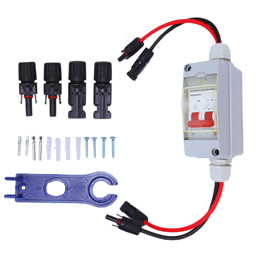
Protective Devices
Appropriately rated fuses or circuit breakers should be installed to protect the circuits against overload capacities. This ensures reasonable protection over current situations.
Routing and Support
Cables shall be routed through ducts, trunking or other enclosures that will protect the cables from being subject to mechanical damage. The cables shall be supported adequately to prevent undue tension and excessive bending.
Earthing
Ensure that all circuits are earthed, including the bonding, in accordance with BS7671 Section 54. This is paramount to safety and fault protection.
Inspection and Testing
After each installation stage, comprehensive inspection and testing stated in BS7671 Part 6, should be carried out. Examples include continuity tests, tests for insulation resistance, and tests for the functionality of protective devices.
Documentation
Traceability must comply with BS7671 for records such as circuit diagrams, test results, and certificates to be maintained.
In addition to the above, but in accordance with the standards, you are also assured of a safe, reliable, and efficient electrical installation system.
How to Ensure Safe Use of 6mm Cables with a 40A MCB?
Choosing the Right Breaker for a 6mm Cable
To use a 6mm cable with a 40A MCB safely, the following information should be adhered to:
Current Handling Capacity
A 6mm cable can handle a maximum current capacity of 47A, but only under the right conditions. Other factors, such as installation method, ambient temperature, and cable grouping, may cause this change. When applicable, always reference BS7671 Appendix 4 to assure data validity.
Breaker Rating Compatibility
A load expected to be higher than the load on the 6mm cable will require utilizing a 40A MCB-rated breaker. The breaker, through additional windings, protects against overloads or short circuits by catering to all areas of overcurrent pertinent to this circuit.
Voltage Tolerance of the Rod
Part of the consideration should include the acceptable voltage loss along the cable’s entire length, as highlighted in BS7671 standards.
Cable Thermal Overload Protection Low Voltage
Always consider derating factors, such as high ambient temperature, and putting the electrical wire in poorly insulated areas, which may impair the cable current capacity. In such cases, alter the 32a ratings or the cable size.
When such data is professionally analyzed, the installation’s reliability and safety while adhering to BS7671 regulations is guaranteed.
Importance of Cable Length and Voltage Drop
The size of the cable is of great importance in the functioning and safety of the electrical system because the length of the actual cable causes a phenomenon called voltage drop which is simply the loss in voltage due to the passage of an electrical current. This voltage drop occurs because of cables; cables cannot be fabricated without resistance, and resistance increases with length, resulting in excessive length. Excessive voltage drop may result in poor efficiency of electrical devices, excessive heating, or destruction of connected devices.
To address voltage drops, policies like BS7671 recommend that for low-voltage installations, the drop should not exceed 3% for lighting circuits and 5% for power circuits. Voltage drop is generally expressed according to the following formula:
Voltage Drop (V) = I x R x L
As an example, a copper 2.5mm² cable running 20A over 30 meters may incur a voltage drop of around 4.2V of resistance. In order to meet the various requirements standards, engineers might have to increase the cable cross-sectional area, lessen the length of the circuits, or even remodel the layouts of the electrical systems.
Also, the cable length has to be compensated for, especially in the case of installations such as data centers or industrial drivetrains that require high power or have critical operations, to reduce the volt drop. If these aspects are neglected, it can hurt operational safety and efficiency. If a thorough analysis is undertaken, the proper design calculations are made, taking into account the volt drop, the proper size of the cables is chosen, and the installation meets the standards and is effective in energy utilization.
Steps for Correct Installation and EICR Compliance
Identify Requirements Within The Installation
I start by determining the electrical requirements of the installation as well as the ambient conditions. This consists of assessing the load, routing of cables, and safety concerns.
Choose Suitable Components
In my evaluation, I address EICR standards regarding cable, conduits, and other components while allowing for the planning of volt drop and efficiency requirements.
Install It Design
In this regard, a well-crafted plan for the butt design would be developed with applicable codes such as UL and other occupancy requirements such as access to the site for inspections and maintenance work.
Place the Order
The input is properly ordered without deviating from the stipulated requirements: design plans according to the installation guide.
Carry out EICR Testing
Armstrong and Sanchia (2012) suggest conducting thorough EICR testing of the installation for any failure or risk alongside the legal and other regulatory requirements.
With every single one of the EICR standards met, I endorse the use of foolproof measures to ensure efficient and safe installations.
What are the Alternatives to Using 6mm Cables for High Load Applications?
When to Opt for 10mm or 16mm Cables
When deciding whether to use 10mm or 16mm cables, I first evaluate the load requirements monolithically with the surroundings of the application forty. I would choose the 10mm cables if the current demand exceeds what the 6mm cables can handle since these are more suited for greater loads like sizeable electrical devices or tiny multiphase circuits. If the application is commercial and more demanding or high-powered, I will use the 16mm cables instead, as they can support even more current loads while decreasing voltage drop and overheating risks. All of these decisions are made after being both precisely calculated & practiced under electrical codes.
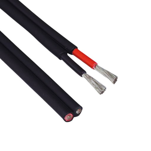
Benefits of Using Twin and Earth vs Twin Core
The choice between T&D and twin core cables relies more on the protective and installation requirements of the specific application. Due to their semi-conductive protective conductors, T&D cables are applicable in building wiring systems, both for residential and commercial purposes. This earth combination enhances safety measures in that ground connection is readily available in case of faults causing considerable risk of electrical shock and damage to equipment. Additionally, T&D cables are appropriate for fixed armored lighting circuits, socket outlets, and ring mains’ installations, considering the strong attachment of foreign PVC materials.
Conversely, Twin Core Some cables lack the earth conductor, which enables them to be used with double-insulated devices or ones that do not require an earth connection, according to the ref method. This reduces the weight of Twin Core cables, making them more flexible and easier to use on portable devices or in only temporary situations. Notably, T&E cables are the most frequently recommended for use in systems with strict electrical parameter compliance, especially where an earth wire is needed, for instance, in the UK. For example, T&E meets BS 7671 regulations for installing wiring in a residential premise powered by 230V.
The voltage and current requirements of the system usually pose a critical chance to determine. T&E is made into a wide range of sizes that give greater load-bearing capacity without risking any damage, whereas the load running on Twin Core should only be minimal for efficient working of low-power devices. In the end, deciding between the two options is critical to factor in the usual rules on the amount of space available for installation and the need for the equipment to function for years to come.
Considerations for Cooker and Shower Installations
The selection of cables for showers and cookers needs special consideration because the appliances require high power that can reach 32 amps. Cookers, for example, run on dedicated circuits with cables between 6-10mm in size, again depending on the power requirements and distance. As a rule of thumb, electric cookers with ratings of 15kW for lesser distances work fine with 6mm cables. Still, when the cooker’s distance or power rating gets higher, it makes sense to switch to 10mm cables to prevent the voltage and heat dissipating increase.
Much like the cookers, electric showers are rated closer to 7kW-10.5kW, meaning they also require a high current, which is higher than the average power between 30A and 45A. It’s best to deduce between 6-10mm cables for these ranges, but other variables such as temperature and installation also impact the decision-making here. For instance, if the cables are installed in tight areas or through insulators, derating factors are an element that needs to be taken care of, making the requirement of cables larger than usual reasonable.
Following BS 7671 regulations, relevant protective instruments such as MCBs and RCDs must also be installed on shower and cooker fittings. Using RCDs rated at 30mA is essential for showers as they come into contact with water and restrict the risk of electrocution. Furthermore, installing these appliances requires appropriate removal switches, such as 45A double-pole switches that must be similar to the load level that joins to ensure safer disconnection during maintenance.
First, let’s talk about installation requirements. For building structures, for instance, shower facilities with high levels of humidity could lead to accelerated deterioration of the exposed sheath to cable elements. Hence, the use of PVC and XLPE cables in the facilities with humidification is encouraged. Moreover, taking care of cable routing during installation if it involves processes that may involve direct contact with hot parts and sharp bends would make sure that the life expectancy and compliance of the system are met.
Why is Choosing the Correct Cable Size Important for Electrical Safety?
Understanding the Risks of Undersized Cables
Using smaller cables is a cause of concern in electrical systems as they’re a safety hazard and performance issue all in one. Cables have a maximum amount of current that they can demand. If they go beyond said demand, these cables tend to overheat. The more heat produced, the more an increase in the electrical resistance, meaning more heat is generated, which can damage the cable’s insulation and thus heighten the chances of short circuits and fires.
Sufficient cable sizes are critical when applying BS7671 coined regulations due to their ability of eliminating voltage drops. Any form of voltage drop would lead to systems becoming inefficient as well as consuming higher energy, a prime example would be if the voltage drop goes over than 3-5% for motors, lighting and other systems, then the devices themselves would stop working or wear out early on. Newer trends have claimed that cables with a smaller size have a lower life expectancy primarily due to how they withstand overload conditions over a prolonged amount of time, for instance operating at 40% more than their intended limits.
It is important to note that using smaller cables impairs the ability to radiate heat, thus increasing the likelihood of thermal damage in high-demand situations. This is especially important in cases where environmental effects, for example, the temperature of the surrounding environment or the bundling of cables, aggravate the heating effect. The current carrying capacity of a cable must be chosen, considering derating factors like the ambient temperature and the way the cable is to be installed, and in such a case, electrical systems can function normally without causing long-term safety issues.
In this regard, it is clear that the requirement to correctly size cables is not only the pressure of the regulations but also aims at making electrical installations dependable, efficient, and safe.
Impact of Load Current and Voltage Drop on Safety
The interplay of load current and voltage drop constitutes an important aspect of the design and functioning of electrical systems. In short, voltage drop refers to an energy loss incurred where electrical current flows through a conductor to generate heat. In case of a high voltage drop at the load side, there will be a decrease in the supply voltage, causing equipment connected to the load to operate inefficiently and, in the worst-case scenario, to malfunction or fail.
On a safety note, there is too much heat generated to the point of melting and damaging components whenever there is excessive load current flowing, which brightens the voltage drop, usually towards the longer lengths of the cable in the case of circuits. For example when voltage drop for branch circuitry is greater than 3% as encouraged by NEC, operational execution becomes inefficient in actuality, combined with a greater than 5% with feeder circuits, along with being a detrimental contributor towards overheating components causing a combustion disintegration of materials insulations failure.
Conductor temperature data suggests that conductors with a voltage drop exceeding the preferred limit can incur up to a 20% uptick in thermal energy loss. This not only increases the risk associated with working around the system, but also significantly reduces its efficiency. The engineers must resolve the problems specified by estimating load currents, the length of the conductors, and the maximum voltage drop acceptable so as to take into consideration the cable sizing.
Increasing the size of the conductors, changing the metal from aluminum to copper, which has a higher conductivity or restricting circuit lengths are some of the solutions that can help minimize voltage drops. Moreover, loose connections, which should be checked periodically, are essential for system maintenance and serve to meet safety and electrical compliance standards.
Electrical systems are capable of functioning in an optimal mode and maintain reliability for a long period without risking safety by taking into consideration the correlation between load current and voltage drop in the initial stages of the design.
Guidelines for Safe Cable Run and Installation
Comply with Acceptable Voltage Drop Scope Limits
As a matter of standard practice, the overall voltage drop should remain within 3 % for lighting circuits and 5 % for power circuits. A deficient voltage drop translates into energy loss as it would diminish the overall efficiency of the equipment cause excessive overheating, and is a health hazard.
Selection, Material, and Size of Conductor
Use copper conductors due to their high conductivity of approximately 5.96 × 10⁷ S/m instead of aluminum 3.77 x 10⁷ S/m. When choosing cable size, consider the load current and distances resulting in the peak operational loads of the conductor not being within the recommended temperature rating limits.
Adhere to Standard Installation Procedures
Position cables sufficiently far from high heat sources to guarantee adequate airflow to a certain degree, thereby preventing insulation degradation and the cable’s overall lifespan. Mechanical stress should also be avoided during installation so that cables can be adequately secured, as too much force on cables can strip insulation damage over time.
Employ Conduit and Trunking for Protection
In situations where cables are likely to be damaged physically or saturated by corrosive substances, it is crucial to apply conduits or trunking. Such measures are especially useful in preventing cuts, abrasions, and rupture of insulation caused by ultraviolet rays in outdoor equipment.
Meet Regional and International Regulations
Adhere to operational and safety requirements such as NEC (National Electrical Code) or IEC (International Electrotechnical Commission), which outline in detail cable installation in terms of voltage drop, size of conductor, etc.
Carry out Regular Testing and Inspections
Such inspections help eliminate problems like loose connections, insulation deterioration, and overheating before they become major issues. Taking thermal images and conducting insulation resistance tests are useful in confirming the reliability of the installation during its life span.
Consider Environmental Factors
Plan cable runs about environmental factors such as temperature, humidity, and chemical exposure. Consider using XLPE (cross-linked polyethylene) insulated cables in areas with high thermal or chemical exposure, but ensure the wire size is correct.
Space Cables Appropriately
In the case of bundling cables, generous spacing should be retained to reduce mutual heating effects and allow for sufficient cooling. Spacers can also be used, or spacing requirements set forth by installation standards can be adhered to.
Incorporating these practices in cable design and installation results in effective electrical systems with higher energy efficiency and lower maintenance costs while providing an extremely low chance of an electrical failure or safety hazard.
Frequently Asked Questions (FAQs)
Q: In general terms, can a 6mm cable withstand a 40 amp current?
A: A 6mm square cable is adequate for a 40 amp current but only under certain conditions. Several parameters influence current carrying capacity, including installation methods, cable types, and ambient temperatures. A 6mm² PVC-insulated copper cable has been known to carry 47A at temperatures above 30 degrees Celsius, but in specific environments (climate B) where the ambient temperature is 0-20 Degrees Celsius, a Method C can be applied to reduce the amperage of the copper wire; hence, consulting an electrician with the wiring plumbing and architecture is advised.
Q: How much current can be passed through a six mm² cable?
A: When installed using method C, a 6mm PVC insulation copper cable should be able to carry a current of 47 Amps but however values may change throughout use and other varying factors such as the environment cable will be used in. However, this value is highly dependent upon the unit being installed.
Q: What would be the interaction between the carrying capacity of the 6 mm cable and voltage loss?
A: The voltage drop must be considered before limiting any cable’s current carrying capacity. At times, running long cables would result in large voltage drops, necessitating a change in the dimension of the cable. The permissible voltage drop for lighting circuits is usually 3%, and for other types of installations, it is around 5% while not exceeding the permissible current rating of the cable. Laws relating to the maximum voltage drop should be observed when the load is 40 amps and the distance is long.
Q: Is it correct to use T&E cables with 40amp MCBs? Is it safe?
A: 6 mm ² cables may be capable of supplying around 40 amps in certain unique cases, but a 40amp MCB should not ever be used with it. Instead, a 32amp MCB should be employed with the 6mm ² cable to ensure safety. Always consult an electrician and adhere to local electricity and cable laying/cabling laws.
Q: Mention the different properties that influence the ampacity of 6 mm cable.
A: A multitude of elements affect the ampacity of a 6 mm cable: 1. The mode of installation (e.g., dug underground, ventilated, or clipped) 2. The external temperature 3. Type of fiber (PVC, XLPE, etc.) 4. The type of conductor (aluminum or copper) 5. Conductors length (in regards to voltage drop spec) 6. Cable combinations 7. Thermal insulation is placed in proximity to the cable.
Q: How does the installation method affect the current carried per length of a 6mm cable?
A: The installation technique has a great influence on the current carrying ability per unit length of a 6mm cable. For instance, Method C (clipped directly) accounts for as much as 47A. The conduit in thermal insulation is about 35A. Free air has a higher capacity as heat is lost better. It is advisable to seek guidance on the correct tables, such as for UK regulations, Table 4D2A, since broad generalizations are made.
Q: For a single-phase 8.5kW electric shower, is it okay to use a 6mm cable?
A: In this case, a six mm² cable can be used as it is reasonable to expect an 8.5K Shower that works on an 8.5kw rating to draw approximately 37A on 230. However, the suitability of a type of cable concerning a device depends on the length of the run, the installation method, circuit protection, etc.; it is best left protected with a 40A RCD. Here also, seek the advice of an electric installer who does proper sizing and installation while considering factors such as a drop-in voltage through the length of the cable.
Q: I am curious how a 6mm cable compares with a 4mm cable in carrying a current.
A: For instance, if both a 6mm and a 4mm cable are measured under C (clipped direct) installation, then there will be an observable difference as features are put into play whereby the approximate value for a 6mm square cable will be around 47 Amps while the other is 35 Amps approximately. To put it in simpler terms, a 6mm square cable will carry more current compared to a 4mm square cable. However, remember that the values multiply depending on the installation method and other factors, so it is always appropriate to consult specific tables in the electrical regulations.
Reference Sources
Insulated Cable Temperature Calculation and Numerical Simulation
- Authors: Xin-Jian Li et al.
- Publication Year: 2018
- Citation: (Li et al, 2018, p. 03014)
- Summary: This paper formulated a mathematical model to determine the cable’s insulation temperature based on the electric current, time duration, and thickness of the insulation layer. The authors modeled the temperature of a 4 mm² PVC cable when kept at 40A and 60A for an indefinite time using ANSYS. The findings elucidated trends over time in the temperature of the layer, which is a very important factor when considering the risk of electrical fires and spontaneous combustion in insulated cables.
- Methodology: The authors conducted numerical simulations to replicate the thermal behavior of the insulation of the cable when subjected to its upper limits of the current load.
2. The Extraction of Measuring Technology Laser PWP Technique via Cable’s External Shield
- Authors: Cong Guo et al.
- Publication Year: 2016
- Citation: (Guo et al., 2016, pp. 1000-1005)
- Summary: This paper presents a new measurement system for such space charge distributions in high voltage direct current (HVDC) cables. It does not, however, deal with 6mm cable only and 40A current rating but reveals the difficulties in measuring the electrical parameters of cables, which is important in cable operation for the load.
- Methodology: The authors carried out space charge distribution measurement using a modified PWP method, and they have substantiated this method by experiments conducted on real-life samples of HVDC cable.
3. Continuous Detection Device of Breaking of Electric Insulation of High Voltage Cable and Its Residual Methods
- Authors: C. Robin, Eric Servel
- Publication Year: 2013
- Citation: (Robin & Servel, 2013)
- Summary: This invention relates to a detection device used for observing the integrity of the insulating sheath of high voltage cable. It does not directly mention the 6mm wire’s 40A capability but rather gives an account of the safety measures that can be used in a high-current wiring system.
- Methodology: The device applies active insulation failure detection through capacitance measurements which is important for personal and equipment safety in high power electrical installations.
Key Findings and Implications
- Thermal Management: This study conducted by Xin-Jian Li et al. shows that a 6mm cable under 40A of current would have elevated temperature, which can lead to the failure of insulation if not properly managed. The simulation results can assist in the design of cable arms that could effectively manage such high currents without thermal failure by optimizing insulation materials and thickness.
- Measurement Techniques: The research papers shared also point towards widening gaps towards development of measuring technology, as mentioned, for cables under load. As these cables should meet or be able to handle specified currents, the ability to detect and prevent failure becomes vital.
- Safety Mechanisms: As was argued earlier, insulation failure detection approaches are essential for preventing some catastrophic events during high current applications. Such technologies should improve the safety in the employment of high current rated cables for example 40 Amps.
Get Your Solar Cable Needs Covered with JOCA – Your Trusted Supplier