








The electrical wiring inside any building essentially lays the foundation of that building’s electrical system, and having a standard color code is really important to ensure smooth functioning and safety. Color codes help in distinguishing wires by their functions: they may be live, neutral, or grounding wires. All these help to prevent accidents due to faulty wiring and to keep the practices in accordance with safety regulations. However, these standards differ from country to country, leading again to confusion for both the tradesman and the homeowner. With this article, we plan to analyze the basic color coding principles in electrical wiring, discuss its importance, and carry out a comparative study between regional standards. In the end, intimate knowledge of which will see you confidently and safely carry out a wiring challenge, all in accordance with the law and regulations where you reside.
Introduction to Electrical Wiring
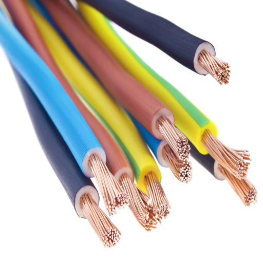
Electric wiring is an array of conductors and apparatus, and machinery employed for the safe and efficient delivery of electric current to operate devices, appliances, and systems. Simply stated, wiring may be cables, connectors, and other related safety devices, depending on the type of electrical load being served and the intended application; in general, the selection of cables depends on various factors such as load density considerations and installation environmental requirements. Being properly installed, the building will work for its intended purpose and will not pose any danger to electrical hazards to its occupants or property. Wiring systems differ in application in the residential, commercial, and industrial contexts; hence, complying with their guidelines and best practices is imperative to ensuring their safe operation.
What is Electrical Wiring?
Electrical wiring generally refers to current infrastructure systems that deliver electrical energy to different settings safely and efficiently. It involves the selection, installation, and maintenance of different conductive wires and apparatuses, all insulated for specific voltages and currents. Copper and aluminum are among the commonly applied materials of wiring, owing to their high electrical conductivity and thermal stability.
An additional update is that about 60% global wiring is in copper because it is most often applied in homes and commercial work, and that aluminum wiring is hardly used residentially, but it is commonly used in high-voltage power transmission lines due to its lightweight and cost advantages. The National Electrical Code (NEC) demands that wiring installations comply with stringent safety standards that prevent fire hazards and maintain operational reliability.
Being able to incorporate the principles of automation gives smart wiring systems the power to operate machinery, working lighting, and other kinds of interfaces. Furthermore, the introduction of fire-resistant cables and sustainable wiring materials has truly changed the face of the industry, so increased safety and environmental benefits are just a bonus. It is therefore a safe practice to adhere to standards such as IEC 60364, UL Listing, and manufacturer guidelines to ensure compatibility and risk reduction. Professional installation and inspection pay dividends over time in efficiency and safety.
Importance of Electrical Safety
Being another side of safety, electrical safety has very critical implications in modern infrastructure, while residences, commercial, and industrial facilities pertain to things affected. Annually, approximately 51,000 electrical-related fires are happening in the United States, according to international safety authorities, causing a staggering number of more than 500 casualties and injuries to 1,400 persons and a million dollars worth of damage to properties, estimated at $1.3 billion. Risks are increased drastically, mainly due to factors such as old wiring, wiring done incorrectly, and an overloaded system, all of which need enhanced safety measures.
Such protection would include GFCIs in any accidental occurrence so that the power could shut down instantly. Also, AFCIs are very important, as they sense and prevent arcs, which are a major cause of residential fires. Strict compliance with safety codes employed for the protection of the design, such as the NEC, will ensure safeguarding against electrical hazards.
The very use of advanced materials and technology, whereby fire-retardant cables could be installed and the smart home would be monitored, is just one of the safety enhancements. These systems work on providing real-time warnings about issues such as circuit overloads or an abnormal temperature rise in the wiring. Professional inspections ought to become a regular occurrence, together with public campaigns to instill awareness about risks and safety measures. Electricity, being an element of our most basic existence, must hence be ensured safe use to protect human lives and properties, and ensure intergenerational sustainability of infrastructures.
Overview of Electrical Systems
Electric systems feature different components that interwork together to generate a supply efficiently and with reliability. Prime components are generation plants, transmission lines, distribution systems, transformers, and end-user appliances. Generation of power occurs from many sources, including fossil fuel, nuclear, renewable energy: solar, wind, and hydro systems. For example, in 2023, some 30% of electricity generation in the world was derived from renewable energy sources, signaling a marked shift toward sustainable energy solutions.
Transmission lines account for transmitting electricity at high voltages over vast distances into the main regions, so that very minimal energy is lost during transit. Substations transform voltage down further for safe local distribution over local networks. The entire system is being monitored and managed using advanced digital technology. Smart grids rely on sensors and the analysis of real-time data to enhance electricity flow while responding to any potential disruption in real-time, which only strengthens the system’s resilience.
What energy storage technologies do modern electrical systems integrate? Both lithium-ion batteries and grid-scale storage operate so that electricity can be delivered at times of peak demand or when the supply from renewables experiences variation. From the perspective of electricity management, advances include smart meters and IoT-enabled appliances, allowing a consumer to identify their usage patterns and optimize for less wastage and efficiency, along with global sustainability objectives.
Electric systems have become an integral part of infrastructure in the modern world, and the continuous evolution of the subject underscores technological advancement alongside the imperative to satisfy energy demand, which is ever-increasing, with effective means. The integration of these renewable resources, energy storage, and smart management systems will need to be the way forward for building resilient, sustainable, and future-proof electrical networks.
Understanding Wire Colors
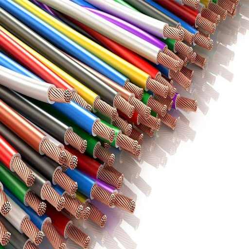
The color codes of wires are standardized to ensure safety and clarity in electrical systems. Usually, black wires are used for a live (or hot) connection; white wires indicate a neutral, while green or bare wires are for grounding purposes. The significance of these color groups is to aid the identification of the wire’s intent, thus minimizing confusion or errors in wiring. Should be consulted as per local electrical codes, for wire color standards are subject to regional variation and must comply with regulatory requirements. Always observe proper safety procedures while handling electrical wiring.
Common Electrical Wire Colors
A wire’s color serves as a crucial visual indication of its functioning in the circuit. By understanding conventions, installations can be done with safety and accuracy. Below is a detailed wire-color manual and its wiring-system application:
- Black Wire: Usually referred to as the live or hot wire in ordinary circuits. Black wires carry current towards outlets, switches, or load points. They are common in residential or commercial systems.
- Red Wire: A hitorous secondary hot wire in 220 volts, such as dryers or various appliances, may sometimes be used as the switch leg when connecting light switches to fixtures in a three-way or four-way switch.
- White Wires (or gray wires): In these wires, the unbalanced load is transferred from the live wire back through them into the power source, completing the circuit. The neutral wires keep the circuits steady and maintain proper voltage polarity.
- Green Wires (or bare copper): Designated for grounding. They allow current to discharge into the earth in the event of a fault, preventing electric shock and damage to equipment.
- Blue and Yellow Wires: Typically seen in commercial applications, blue wires are used as travelers in three- or four-way-switch systems. Yellow wires are commonly used for switch legs or for live wires inside conduit systems.
- Orange Wires: From time to time, used in 240-volt applications and in industrial environments. These wires indicate live or phase conductors, mostly in very large multi-phase systems.
It must not go unnoticed that the practices listed herein are generally those applied within the industry, yet divergent trends can exist, dependent on geographic location, application, or sometimes project requirements. For instance, in the USA, this sort of convention is governed by the National Electrical Code (NEC). Contrarily, other countries have significantly different standards for wiring color; thus, local electrical codes and regulations should always be consulted before any installation or repair undertaking.
By following these color-coding practices and considering modern industry standards, electricians and technicians will minimize as much as possible the chance for error and allow the safe and efficient distribution of power throughout all of these systems.
Significance of Wire Color Code
This way, rapid communication on which conductor does what and what the wire color represents is wire color coding, which forms an integral element of any electrical system. Working for the enhancement of safety, it facilitates easier troubleshooting and thus speeds up maintenance. For example, according to the NEC of the U. S., black and red colors are popularly considered “hot” conductors in residential circuits, white is for neutral, while green and bare copper are thus used for ground wire.
Wiring color codes differ globally due to varying regulations and electrical system requirements in each country. In the European Union, standards are in accordance with IEC 60446, where brown is usually specified for the phase (live) conductor, blue for neutral, and green with yellow stripes for the protective earth (ground). A reduction in wiring errors had been noticed in accordance with such standards, with the working papers stating a drop of about 18% in installation-related electrical failures in systems that conform to the new color coding regulations.
When wire functions are not identified properly, disastrous consequences follow: electrical shocks, equipment damage, and even electrical fires. Keeping in accordance with international or local regulations ensures that electricians and technicians can work safely and effectively, especially where complex systems such as industrial power grids or multi-phase installations are concerned.
Introduction to Wire Color Code Standards
Wire color code standards provide a really important framework for ensuring the safe and efficient operation of the electrical systems. Depending on the country and region, wire color codes may differ to adhere to local rules and needs, but the overriding goals are universal: to create a language that all electricians understand for the function of given conductors. The NEC in the United States, for example, states that green or green with a yellow stripe is for grounding wires, white or gray is for neutrals, and black, red, or other colors are generally used for hot or live wires. Compared to U. S., the European wiring convention under IEC standards considers blue to mean neutral wire and brown the live wire.
Data suggests that standardizing wire color codes significantly reduces electrical hazards. In an industrial setup wherein three-phase systems are generally predominant, designated colors for phases must be used consistently: black, red, and blue (or brown, black, and gray in IEC systems); thus, these colors allow fast identification during installation and maintenance, minimizing downtime and errors. In the same vein, non-standard or abused color codes continue to be a major source of accidents, cementing the need to remain compliant with established codes.
Due to novel styles of renewable power installations like solar photovoltaics, the conventional coding must be adapted to alternate options accordingly. Standards now dictate the use of red for positive DC conductors and black for negative DC conductors to distinguish them from AC systems. It is in the interest of global sustainable energy that this unification takes place, which means that the wire color code standards have always been wired based on the latest electrical demand.
Electrical Wire Color Code Standards by Region

Electric wire color codes are region-wise, thereby causing confusion in potential wiring installations. Below are the wire color codes considered standard in some principal regions:
| Region/Standard | Live/Hot Wire | Neutral Wire | Ground/Earth Wire |
|---|---|---|---|
| United States (NEC Standards) | Black or Red | White or Gray | Green or Bare Copper |
| European Union (IEC Standards) | Brown | Blue | Green-Yellow Stripe |
| United Kingdom (BS 7671 Standards) | Brown | Blue | Green-Yellow Stripe |
Adherence to these standards will indeed help to ensure safer and reliable electrical installations, thus eliminating the possibility of confusion and risk of hazard. Always check local rules and regulations in the event of specific requirements.
National Electrical Code (NEC) Guidelines
The National Electrical Code (NEC) or NFPA 70 is the official designation presented for safe electrical installation practice in the United States. It offers precise instructions to be followed in the interest of safety, efficiency, and uniformity of various electrical systems. The NEC mentions key wiring color standards comprising:
- For Black Wires: Used mainly for live (hot) connections in both residential and commercial settings.
- White or Gray Wires: Are neutral conductors; they carry current back to the power source.
- Green or Bare Copper Wires: Are used for grounding and preventing electric shocks under fault conditions.
- Red Wires: Are used as a secondary hot wire in a 220-volt installation or as a switched hot.
- Blue and Yellow Wires: May be used for travelers in three-way switches or for special circuits in industrial applications.
NEC supports consistency and conformity to wire color standards for a mutually minimizing risk of error on installation, maintenance, or troubleshooting. An electrician or contractor generally has to check the most recent revision of the NEC, which comes out every three years, to make sure that they are compliant with the state or local regulations.
International Electrical Wiring Color Codes
Since the electrical wire color code is one of such must-have regulations that assure safety, uniformity, or ease of troubleshooting, different countries have varying codes. The International Electrotechnical Commission has set specific color codes as per the International Standard IEC 60446 for most nations to keep things uniform. The neutral wire in a single-phase system is mostly colored blue, the live or phase wire brown, and the protective earth or ground wire green with yellow stripes. It is the prevalent standard in many parts of Europe and elsewhere.
In North America, electrical wiring is done according to the National Electrical Code (NEC). Here, the neutral wire, by tradition, would be white or gray; the live or hot wire black, red, or some other color depending upon phase designation; and the ground wire would be green or bare copper. Although the NEC has standardized wiring domestically, older systems or localized practices maintain some variance in international references.
For three-phase systems, the IEC standard provides a comprehensive listing of colors-brown, black, gray-for the live wires, blue for neutral, and green/yellow for ground. Adhering to these standards in industrial, commercial, and residential systems is highly desirable for both consistency and safety across regions, especially in instances where equipment or maintenance personnel may be from multiple regions.
Electricians and engineers ought always to check the standards prevailing in a certain region before engaging in any wiring work, especially in cases involving international or imported equipment, since disregarding these standards could lead to the equipment not working or presenting a significant danger. As is usually the case, professional practice entails that one continually consults updated national and international codes.
Detailed Breakdown of Wire Colors

When working on electrical wiring, the color codes need to be understood for safety and functionality. Identification of the colors of wiring correctly ensures the correct connection and reduces the likelihood of electrical hazards. Always check with the latest regional electrical codes for any work in installations.
Red and Black Wires
Electricians often assign red and black wires specific functions, depending upon location or application. In older wiring systems, for instance, red would conventionally designate a live (line or phase) conductor while black would commonly signify a neutral conductor. Yet, the use and meaning of red and black wires may well be different in particular contexts and local electrical codes.
For example, according to the National Electrical Code (NEC) in the U. S., normally, the black wires are live wires for single-phase 120-volt circuits, while red wires may be used as secondary live wires in particular instances, such as switch legs and wiring between three-way switches. Unlike this, however, in certain applications, such as in 220-volt configurations, the red and black wires can be live phases.
Some older fixtures or non-conventional setups might not conform to present-day color-coding standards. This also stresses the relevance of ensuring the use of proper tools, like a voltage tester, to check the functionality of a wire before starting an electrical job. For everyone’s safety, ensure that you always abide by the electrical codes of your region and certified documentation when identifying or working with either red or black wires, so as to minimize the risk of miswiring.
White and Gray Wires
Typically, white and gray are neutral wires in electrical systems, serving the purpose of allowing electric current to return to the electrical panel. Considered an integral part of the circuit and in this way maintaining the flow of electricity, these wires with functional may be considered interchangeable. While white wires are more common, gray wires may be present in some installations, particularly older or industrial systems. They should not, according to NEC, be used for hot or live wiring, unless with proper marking (e.g., electrical tape). Strict inspection of the configuration and labelling is environmentally important during any electrical procedure because false identification could result in dangerous situations or equipment failure. Always check connections with a multimeter and consult your local regulations for proper use instructions and safety.
Green and Copper Wires
The National Electrical Code designates these grounding conductors as green or bare copper wires. In case of a fault, the wire provides the safety path for electrical current to return to earth; otherwise, the user can suffer from electric shock, and damage can occur to equipment. During normal operations, these wires never carry current and must never be used as hot or neutral wires. While installing or repairing wiring systems, since ground wires’ connection to the ground system (e.g., ground rods or metal water pipes) must be checked with a reasonable continuity resistance to ensure safety and fault protection, always follow local electrical codes for grounding compliance and employ proper testing equipment like a multimeter.
Applications of Wire Color Codes
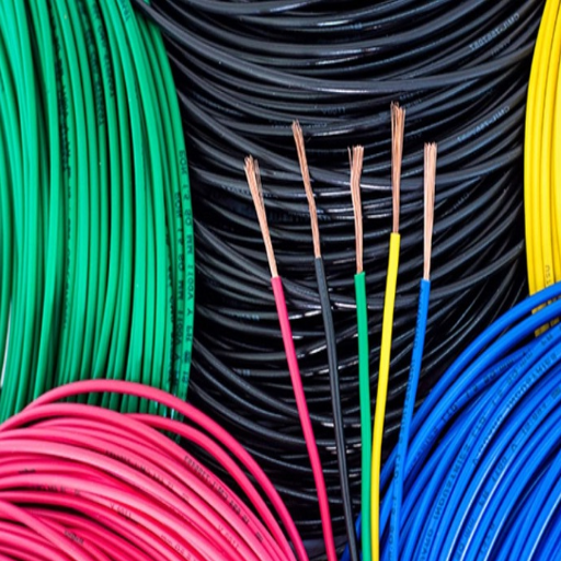
Wire and cable color-coding is essential for the consideration of safety and efficiency in a working electrical system. This gives a person a correct, established coding to identify each wire in a given circuit as to its intended use. For example, black or red wires are supposed to carry live or hot currents, whereas neutral connections will have white wires. Grounding is given protection by green or bare wires, which strictly provide a ground path for fault currents. The use of wire color codes helps in avoiding confusion in installation and maintenance and increases safety. Be sure to consult the applicable codes, such as the National Electrical Code (NEC), for specific color standards.
Home Wiring Systems
The systems of wiring are important for the transmission of electricity at an equal rate of safety and efficiency throughout a residential building. The commonly considered types of home wiring systems are the following:
- Conduit Wiring System – It uses protective pipes called conduits made out of materials such as PVC or metal, etc., for housing the electrical wires. It is very durable and offers maximum protection against external damage, moisture, and corrosion.
- Non-Metallic (NM) Sheathed Cable Wiring – Known as Romex wiring, it commonly refers to the use of flexible cables having plastic sheathing to enclose wires. NM cables are weightless, inexpensive, and commonly employed in residential applications.
- Cleat Wiring System – The system uses insulated wires that are attached to walls or ceilings through porcelain or plastic cleats. They are seldom deployed for permanent wiring, but can be used practically as a temporary solution.
There are vast considerations to make when choosing a wiring system; all of them include, more notably, safety and cost, the structure of the building, and adherence to local codes, for example, the NEC.
Power Wiring and Circuit Design
When thinking about power wiring and circuit design, I take a systematic approach to the whole topic by considering the specific requirements of the project with respect to load demands, building layout, and safety standards within the set timeframe. Foremost among considerations are codes such as the NEC, performance aspects, and safety. I concentrate on the proper selections for conductor sizing, protective devices, and configuration of circuits to give the best performance at the lowest cost, but not so low as to compromise the premises’ safety from dangers of overload or short circuit.
Electrical Components and Their Significance
Electrical components are essential for any electrical system. Each of these components has a function to ensure the system’s efficiency and safety. The principal components that find application in circuits are resistors, capacitors, inductors, diodes, and switches. Resistors impede the flow of currents and provide voltage drops, whereas capacitors store and release electrical energy. Inductors may limit or release the flow of energy through magnetic fields. Diodes allow current flow in one direction only, preventing the flow of current from the other direction. Switches might be either manual or automatic.
These components constitute the building blocks of larger systems that must operate properly. In power distribution systems, for example, transformers and circuit breakers are critically important. Transformers are used to vary voltage levels so as to transmit power efficiently, whereas a circuit breaker would interrupt an excessive flow of current, protecting the system from damage or hazards. The interaction of such components steers the system towards sustainable operation, compliance with safety standards, and utilization of energy in the present-day electrical system.
Reference Sources
“Ant Colony Optimization for Resistor Color Code Detection”
- Key Findings: The principal objective of this research is to recognize the color codes of resistors by means of the ant colony optimization techniques. It underlines the significance of the application of colours in the electrical parts for controlling the voltage and resistance.
“Risk Propagation Analysis and Visualization Using Percolation Theory”
- Key Findings: The application of color codes for visualizing risk probabilities in the systems is one of the core contributions of the paper, which can also be extended to physical links such as electrical systems.
“PARTIAL DISCHARGES AND IEC STANDARDS 60840 AND 62067: SIMULATION SUPPORT TO ENCOURAGE CHANGES”
- Key Findings: The study has revealed that the utilization of power cables and their conformity to IEC standards are the main topics of discussion, but indirectly, the matter of standardization in electrical systems has been highlighted as well.
Frequently Asked Questions (FAQs)
What are the electrical wiring color code standards?
Electrical wiring color codes are standards or guidelines prescribing the colors of wires used in electrical projects. Such codes help specify the function assigned to any given wire, an important feature for safety and uniformity in electrical work. Some of the widely used standards are the National Electrical Code (NEC) in the United States and the Canadian Electric Code, specifying wire colors for various types of wiring, e.g., grounding and power wiring.
How do color-coded wires indicate the functions of wires in an electrical circuit?
Color-coded wires show the visual cues in the identification of their special functions inside an electrical circuit. For instance, the black wire is usually a hot wire carrying electrical power, while a white or gray wire usually denotes a neutral wire. Green wires are employed for grounding purposes to avoid electrical hazards and maintain electrical safety.
What is the importance of standardized color codes in residential wiring?
Standardized color coding assigns hues to wires for safety and other electrical applications. These colors allow any person working on the electrical system, be they a licensed electrician or a green-handed DIY guy, to easily determine the functions of the wires. This reduces the possibility of errors during electrical work, and accidents or damage to the electrical equipment might occur.
Explain the wire color code chart for common wire types.
A wire color code chart offers a visual guide in understanding the uses of different colors of wires. For instance, in most areas, black wires are used for hot connections, white for neutrals, while green and bare copper are used for ground. Familiarity with the chart is a requirement for any wiring project participant to comply with electrical codes.
How do electrical color codes get affected by the Canadian Electric Code?
The Canadian Electric Code (CEC) specifies regulations for electrical wiring; this includes color codes. The CEC states that particular color codes are reserved for the application of wires, much like the NEC. For instance, it allows red wires to be used as hot wires under certain conditions, and this, for instance, would be important to note for someone performing electrical projects in Canada.
What kinds of electrical problems can arise if one fails to observe proper wire color code standards?
Failing to observe color code standards may result in short circuits, electric shocks, or even fires. When one misidentifies a wire function, improper connections may damage electrical equipment or constitute a hazard to the electrical infrastructure. Therefore, adherence to these standards is mandatory to avoid electrical mishaps.
What are the common wire colors used for electrical conductors?
Typically, in electrical work, wire colors vary as follows: black for hot wire, white or gray for neutral wires, and green or bare copper for ground wires. These wire colors are highly consistent with standard electrical practices, and are set therefor easy to identify by an electrician or technician regarding the role of each wire during installation or for troubleshooting electrical systems.
How should one distinguish between wire types in their existing wiring?
One can distinguish between types of wires in their existing wiring in accordance with the wire color code standards established by the NEC or similar local standards. Visual inspection of the insulation can tell the story of the working function of the wire. If the wiring appears to deviate from the standardized codes, it is best to consult an electrician to be sure of their safety and to meet the required electrical standards.