If reliability, performance, and safety are to be considered under the electric infrastructure for diesel locomotives, they are unrealizable wishes. Diesel Locomotive cable plays a vital role in fulfilling these demanding operational conditions, which require efficient power transmission under harsh situations. But what is a DLO cable? How does the ability to carry electric current affect the rate of good performance of these cables? This article provides a comprehensive examination of DLO cable, covering its ampacity ratings, construction, applications, and other uses in the rail sector and beyond. Whether you’re a practicing engineer or not, this book can educate you about why this cable is one of the widely accepted choices in high-rated electric systems.
Introduction to Cable and DLO Cable
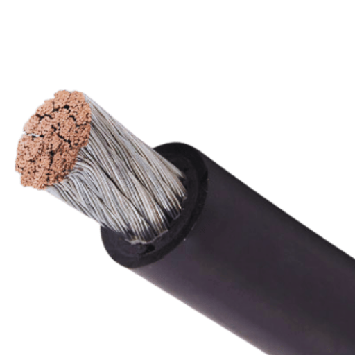
A cable is a vital component of any electrical system, enabling the safe and efficient transmission of power, signals, or data. Among the myriad types of wires, DLO (Diesel Locomotive Cable) is known for its robustness and versatility. Being a flexible, high-performance cable, it can carry a high current load due to its high ampacity. It is made up of finely stranded copper and top-tier insulation, which resists oil, heat, moisture, and mechanical stress. These properties give DLO cables the much-needed reliability and performance, particularly in demanding applications within the rail, mining, and power generation industries.
Definition of Cable
A cable is an assembly of one or more conductors, sometimes insulated and bound together, for the transmission of signals or the flow of power, from one place to another. Cables are essential components of any electrical or electronic system, and they come in various forms, depending on their construction, intended use, and performance requirements.
Cables are generally classified according to the material of their conductors, such as copper or aluminum, and the insulation used, which can be PVC, rubber, or XLPE (cross-linked polyethylene). For instance, copper cables are preferred due to their superior conductivity, high flexibility, and strength, making them suitable for use in both residential and industrial applications.
In considering size, the cable is apt to carry current safely (called the ampacity). For example, in the comparable cross-section, a copper conductor has a higher ampacity than an aluminum one. The voltage rating is another important specification as it defines the maximum ideal operating voltage at which the cable can be safely operated.
Today, according to modern design and usage, cables may incorporate additional features to cater to different needs. For instance, shielded cables feature a layer of metal or foil to mitigate or reduce electromagnetic interference (EMI). In contrast, armored cables have protective outer layers that resist mechanical stress, enabling them to be installed underground or in harsh environments. Multi-core wires, which carry several conductors inside an outer jacket, are often used to simplify wiring requirements in complex electrical systems.
Profound improvements have been made in cable technology, particularly in terms of fire resistance, lightweight construction, and the use of eco-friendly materials. These advancements have enabled applications in renewable energy, telecommunications, and high-performance computing networks that adhere to global safety and sustainability standards.
What is DLO Cable?
A waterproof and flexible cable, the DLO (Diesel Locomotive) cable, is designed for heavy industries and high-demand electrical applications. Originally designed and produced for diesel-electric locomotives, these are now primarily applied in other sectors due to their robust construction and exceptional performance capabilities under harsh working conditions.
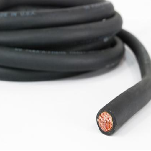
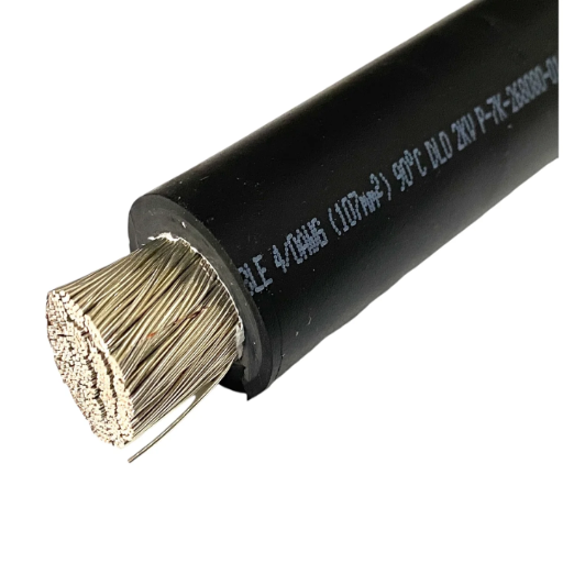
Typically, DLO cable uses copper conductors, finely stranded to ensure maximum flexibility and conductivity. These conductors are insulated with EPR, the best dielectric material available in terms of both dielectric strength and thermal endurance. A thick chlorine polyethylene jacket covers the cable. The coat and cable together offer high resistance to attack by chemicals and oils, abrasion, and weathering, including extreme weather conditions ranging from -40°C to +90°C.
DLO cables are primarily used for very high current loads; their voltage ratings typically range from 2,000 to 3,000 volts. These cables are flame-retardant and comply with UL 1277 and CSA safety standards, making them well accepted by the MSHA (Mine Safety and Health Administration) for use in the mining industry. Initially used in locomotives, these materials are now widely employed in renewable energy systems, batteries, power distribution, industrial machinery, and marine applications, where reliability and durability are paramount.
Flexibility, toughness, and electrical performance in one package make DLO cable a crucial element of modern industrial electrical systems, which require unfaltering performance in the most challenging conditions.
Importance of Cable Ampacity
In this chapter, we will define the term Cable Ampacity, which is essentially the current-carrying capacity of a wire or cable. The correct ampacity ratings must be observed to prevent wire fires or other hazards that may occur. The ampacity of a cable varies depending on the material of the conductor, the type of insulation, the ambient temperature, and the installation conditions.
For example, copper conductors are generally better at carrying current than aluminum conductors due to their superior conductivity. A 4/0 AWG copper conductor may be rated for approximately 230 amperes in free air at 75 °C insulation. The same gauge aluminum conductor may only be rated for approximately 180 amperes under the same conditions. Insulation plays a significant role as well—the higher the temperature rating of the insulation material, the higher the ampacity can be.
The installation environment is also critical. When cables are packed side by side in groups or inside conduits, heat dissipation decreases, thereby lowering the effective ampacity. NEC instructions will specify correction values to be applied for adjusting the ampacity under these conditions. For example, with an increase in ambient temperature from 30°C to 40°C, ampacity decreases by about 10-20%, depending on the cable type.
Correct determination of cable ampacity ensures the maximum performance with minimal risk. Proper design and cable selection, based on ampacity ratings, protect critical electrical systems, enhance safety, and improve the overall efficiency of residential and industrial installations.
Specifications of Diesel Locomotive Cable
Diesel locomotive cables are manufactured to meet industry-set standards concerning safety and performance. The wires must withstand high operating temperatures, ranging from -40°C to 90°C, while remaining flexible and durable. They are primarily assigned a strong insulating material, such as EPR (Ethylene Propylene Rubber) or similar compounds, to resist oil, moisture, and physical wear and tear. Depending on the application, the voltage rating of such cables typically ranges from 600V to 2000V. Additionally, the construction of these cables often involves the use of flame-retardant materials to ensure they meet critical ASTM or IEC standards and can be relied upon in harsh operating environments.
Key Specifications of DLO Cable
Voltage Rating: Regarding voltage, DLO cables can range from 600V to 2000V, accommodating various power distribution levels or industrial applications.
Conductor Material: As they feature tinned copper conductors, they provide excellent conductivity and corrosion resistance, enabling long-term operation in harsh environments.
Insulation Material: Insulation typically consists of Ethylene Propylene Rubber (EPR), with an outer jacket of Chlorinated Polyethylene (CPE), providing the cable with resistance to oil, moisture, abrasion, and chemicals.
Temperature Range: DLO cables are designed to operate in an environment ranging from -40 °C to 90 °C (-40°F to 194°F), whether wet or dry, ensuring their reliability is universally recognized.
Flame Resistance: These cables meet multiple flame-retardant standards, including ASTM B33 and IEC 60332, making them even safer to handle in critical applications.
Flexibility: Designed with wonderful wire strands, can DLO cables be made more flexible, making any type of installation in confined or complex spaces easier?
Applications: Typically powering plants, mining sites, locomotives, and renewable energy systems, they are meant for heavy industry.
Mention of these specifications positions DLO cables as a versatile, durable, and safe solution for trusted operations in demanding contexts.
Ampacity Ratings for Diesel Locomotive Cable
The ampacity of a cable refers to the amount of electrical current it can safely conduct without overheating beyond its temperature rating. Due to specific ampacity ratings assigned to them, DLO cables are ensured to deliver adequate performance, with safety considerations taken into account across a range of operating conditions.
The determination of a DLO cable’s ampacity is based on several factors, including conductor size, insulation type, ambient temperature, and installation conditions. Here is the ampacity rating in a general way corresponding to conductor sizes more commonly applied in industrial applications:
2 AWG: 190 amperes at 90 °C in free air or 115 amperes in conduit at 30 °C.
1/0 AWG: 260 amperes at 90 °C in free air or 150 amperes in conduit at 30 °C.
4/0 AWG: 370 amperes at 90 °C in free air or 260 amperes in conduit at 30 °C.
350 kcmil: 520 amperes at 90 °C in free air or 350 amperes in conduit at 30 °C.
500 kcmil: 625 amperes at 90 °C in free air or 430 amperes in conduit at 30 °C.
For installation in higher-temperature environments or bundles, a derating factor may be required to ensure the cable operates within safe limits. Always consider industry standards, such as the National Electrical Code (NEC), when determining the right ampacity for specific applications.
The ampacity ratings of DLO cables, when selected correctly, help ensure the cables are reliable and avoid overheating, which impacts both performance and safety.
Compliance with NEC Standards
The National Electrical Code is a comprehensive set of standards that ensure the safety and efficiency of electrical installations, including specific requirements for cable ampacity. According to NEC Article 310, the ampacity of conductors varies depending on the insulation type, ambient temperature, and whether the cables are installed inside a conduit, in open air, or bundled together. For DLO cables, popular insulation types such as EPDM and EPR are rated for a temperature rating of up to 90°C, supporting good current-carrying capacity even under adverse operational conditions.
Table 310.16 of the NEC paints a wonderful picture during the ampacity evaluation process. For instance, the ampacity of a 1 AWG copper conductor under standard conditions (ambient temperature of 30°C and installation in free air) with 90°C insulation is 130 amperes. Correction factors must be applied for installations in high-ambient-temperature conditions. At an ambient temperature of 40°C, for example, the considered ampacity should be multiplied by a correction factor of 0.91, reflecting an ampacity value of approximately 118 amperes. Further reduction shall occur when cables are bundled, as specified in Table 310.15(C)(1), due to increased heat dissipation.
Following the National Electrical Code ensures conformity and operational safety against overheating and damage. This consideration should hold paramount importance when considering installation guidelines, especially for industrial and high-performance applications. However, such concerns must be addressed at every possible opportunity, with code updates checked regularly to address the ever-evolving nature of safety.
Applications of DLO and Diesel Locomotive Cables
Diesel Locomotive (DLO) cables are largely versatile in industrial and transportation applications, owing to their durability and high performance. These are primarily used in power systems for diesel-electric locomotives, where efficient power transmission is required under arduous conditions. Furthermore, DLO cables have applications in renewable energy systems, such as solar and wind power, where they are needed to handle heavy electrical loads. Lastly, these cables are extensively used in the marine and mining sectors, where reliability and resistance to harsh environments are crucial. In general, DLO cables serve as a versatile power transmission medium for all situations wherein power needs to be transmitted robustly and dependably.
Typical Applications in Locomotive Systems
The uninterrupted movement of trains requires DLO cables to play an essential role in modern locomotive systems. An everyday use is to supply traction motors with power, ensuring the transfer of energy to propel the train. Due to their resistance to high temperatures, DLO cables have also been able to withstand vibrations and mechanical stresses imposed by locomotive environments.
In particular, electric and diesel-electric traction systems power heavy electric loads using DLO cables, ensuring smooth and efficient operation. An electric locomotive must handle voltages exceeding 600V through these cables that provide uninterrupted power flow from transformers to the motors. In the diesel-electric arrangement, on the other hand, DLO cables are used to interconnect the alternator and rectifiers with the motors that generate and distribute power to the train’s drivetrain.
With the ever-increasing growth of electrified rail networks globally, the demand for power cables that can withstand the harsh environments in locomotives is expected to maintain its growth rate, say industry reports. The markets in regions such as Europe and the Asia-Pacific have witnessed an increased use of electric trains that require the bulk usage of high-performance cables, such as DLO. Hybrid and battery-powered locomotives are also DLO cable users for their effective energy management, so with the push for green rail transport.
Enhancing the reliability and cost-effectiveness of DLO cables by reducing downtime and maintenance costs in locomotive operations makes them more reliable and considerably cost-effective. Thus, DLO cables remain an ultimate element in the evolution of modern rail systems.
Use in Harsh Environments
DLO cables, specifically designed for Diesel Locomotive Cable, are manufactured to withstand some of the harshest environmental conditions and are therefore used in extreme settings. The cables are constructed with high-temperature-resistant EPDM rubber insulation and an oil-, abrasion-, flame-, and chemical-resistant jacket, ensuring they can reliably perform in all extremes, from intense heat to cold.
In recent years, it has been concluded that DLO cables can operate within a reasonably wide temperature range, typically from -40°C to 90°C for continuous use, or -40°F to 194°F. Additionally, since they are ruggedly built, they exhibit excellent dielectric strength even in the presence of UV radiation and moisture, a crucial characteristic for outdoor and industrial applications. For instance, mining can use the flexibility and durability of DLO cables, whereas the marine environment and offshore energy installations require the same from these cables. Test data indicate that the wires perform well under harsh stress conditions, such as environments with heavy vibration or prolonged contact with oil and corrosive substances.
With their robust structure and consistent electrical conductivity, they have become the preferred solution for harsh environments, enabling long periods of uninterrupted operation while minimizing the potential risks of failure or electrical degradation. Marrying strength and superior electrical properties, DLO cables continue to fulfill the requirements of industries seeking reliable power transmission in the harshest of environments.
Comparative Analysis with Other Cable Types
The ampacity of DLO cables varies depending on the wire size and insulation, but typically ranges from 35 to 885 amps. Below is a concise summary in tabular format:
|
Wire Size |
Ampacity |
Voltage |
Temp |
Use Case |
|---|---|---|---|---|
|
14 AWG |
35 A |
600 V |
90°C |
Light Duty |
|
6 AWG |
105 A |
2000 V |
90°C |
Medium Duty |
|
2 AWG |
190 A |
2000 V |
90°C |
Power Apps |
|
4/0 AWG |
405 A |
2000 V |
90°C |
Heavy Duty |
|
500 MCM |
665 A |
2000 V |
90°C |
Industrial |
|
777 MCM |
885 A |
2000 V |
90°C |
Large Scale |
This table provides quick insights into the ampacity, suitable voltage levels, temperature ratings, and typical usage scenarios for DLO cables across different sizes.
Wiring and Termination Techniques
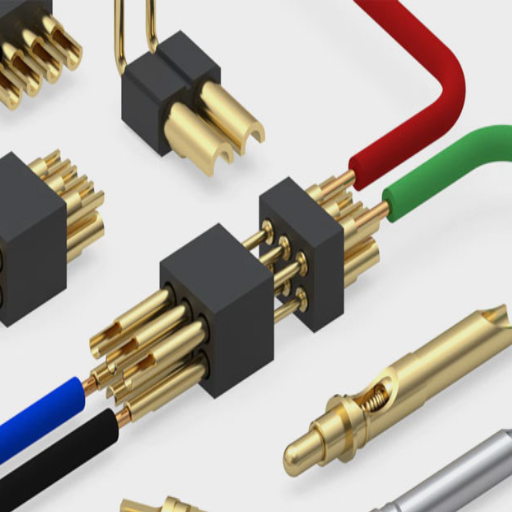
Wiring and termination are among the most critical operations in terms of safety, reliability, and efficiency in an electrical system. When working on DLO cables, selecting connectors that match the cable’s size and insulation type is essential. Strip away the insulation carefully without damaging either the conductors or their surface, and use suitable crimping or compressing tools specified by the connector maker. Ensure the connection is tight, free from loose ends, and has no improper terminations. Such guidelines must be strictly adhered to, and industry standards followed to minimize any risk while maximizing installation performance.
Overview of DLO Wire Termination Kits
DLO wire termination kits are crucial for ensuring safe, proper, and efficient connections for highly demanding electrical installations. These kits typically include the correct size of lugs and connectors, as well as heat shrink tubing, which works well with flexible, multi-stranded DLO cables. The DLO wires are renowned for their robustness, high electrical conductivity, and resistance to oil, chemicals, and high temperatures; therefore, they are widely used in industrial, locomotive, and power generation fields.
When selecting a DLO wire termination kit, it is crucial that the wire gauge and insulation type match. Generally, the kits will contain heavy-duty crimp or compression lugs to allow secure, low-resistance terminations. An additional layer of insulation is provided by the application of heat-shrink tubing, which is included in most kits. This layer protects from environmental factors and further enhances durability. Installation methods, such as properly stripping the cable insulation and applying the crimp terminations with manufacturer-specified tools, ensure a reliable termination.
DLO wire termination kits generally make the process of joining and terminating these specialized cables easier, with safety, performance, and efficiency standards expected in the industry. When used and installed correctly, these kits provide minimal electrical losses, reduced maintenance, and increased system lifespan.
Proper Use of Wire Strippers
Stripping wires correctly is necessary to maintain the integrity of any electrical connection, as well as its intended performance. Wire strippers are available in various types, including manual, automatic, and multi-function models, among others. Each of them is designed for wires of a specific gauge, featuring a particular type of insulation. For finer results, the slot in the wire stripper intended for a specific gauge of wire must match the actual wire size being used, usually measured in AWG.
Damage to the conductor strands may be a concern when removing the insulation from larger-size cables, such as DLO cables. Nicked strands could cause problems such as increased resistance, power overheating, or outright system failure. It has been demonstrated that a proper stripping method, utilizing the correct tool, can reduce insulation damage by approximately 80%, thereby ensuring the system’s reliability. Furthermore, maintaining the stripping length at consistent values, set by project parameters, leads to superior crimping quality and connection quality.
Wire strippers should undergo routine maintenance, including cleaning the blades and sharpening them when necessary, to prolong tool life and ensure consistent use. It is even advisable to replace blades once they are dull, since continued usage only reduces effectiveness and may end up tearing the insulation instead of cleanly cutting it. Along with the understanding, the implementation of best practices would enhance safety, reduce waste, and bring integrity into electrical connections.
Best Practices for Cable Termination
The termination of electrical and data cables must be done correctly to ensure system reliability, safety, and longevity. Below are some detailed best practices and insights that would help in optimizing cable termination:
Selecting the Right Tools: Great terminators rely on high-quality tools, typically precision wire strippers, crimpers, and cutting tools. For instance, tools designed for use with a specific wire gauge cannot be misused to cut or crimp a wire, as such alterations could compromise the quality of the wire. For large projects, the tools should be ergonomic to avoid operator fatigue.
Prep the Cable: Every termination starts with cable preparation. Strip the insulation carefully to the correct measurement from one end, ensuring no damage to the wire (also called conductors) within. Additionally, for shielded cables, ensure that the shield is intact and properly folded back to prevent EMI from compromising signal integrity.
Proper Length and Bend Radius: Cut the cable to the correct length to avoid excess slack that may tangle or cause signal loss. For bend radius, maintain the minimum radius, usually five times the diameter of the cable, to avoid stress on the conductors that could degrade performance, especially fiber optics and structured cabling systems.
Use Good Connectors: Ensure your connectors match the cable types and cable specs. For example, use RJ45 connectors rated for Cat6 cables to achieve system compatibility and data transfer speeds. Using poor connectors can result in system failures and underperformance.
Testing: Testing is also critical after the termination to confirm the quality of performance. Tools used for testing include continuity testers and network certifiers, among others, to ensure continuity, proper connection, and conformity to standards such as TIA/EIA-568 for structured cabling. Improper terminations may cause data loss, signal distortion, or downtimes.
Environmental Considerations: While terminating cables, keep ecological considerations in mind. For installations in outdoor or industrial environments, select connectors and cabling that are rated for resistance to moisture, temperature extremes, and corrosion. Seal the connections with weatherproof sleeves or boots for even greater protection in hostile environments.
Standards Compliance: Adhere to recognized standards, such as TIA, ISO/IEC, and local electrical codes, to ensure compliance and reliability. Standard methods reduce the incidence of errors, ensuring uniform performance in implementation.
Labeling and Documentation: Proper documentation and labeling of cables and connections will facilitate easier maintenance and troubleshooting. Use heat-shrink labels or clip-on tags to identify cables, especially in complex systems, properly.
By following these best practices for the cable termination procedure, you will significantly reduce the likelihood of common pitfalls, such as signal interference, mechanical failures, and downtime. According to data, the adoption of these practices could enhance system efficiency by as much as 30% within very demanding environments. When quality becomes an obsession, it naturally leads to enhanced performance and improved longevity for your networks and electrical systems.
Compliance with NEC Standards
Compliance with the NEC ensures that an electrical system is safe and reliable. To ensure compliance, it is essential to adhere to key guidelines, including the use of approved materials, proper grounding, and ensuring the installation meets the defined clearance and load capacity requirements. Since processes may be updated with NEC changes, consider regular inspections and adapt to codes as they evolve. Compliance diminishes fire and electrical hazards, ensuring the system is efficient and legally compliant. Always make it a habit to check the current NEC handbook or seek advice from a qualified professional regarding regulations concerning your project.
Overview of NEC Requirements for Cable Installation
The National Electrical Code (NEC) serves as a comprehensive safety and efficiency code for cable installation in all residential, commercial, and industrial settings. Adhering to the standards of the NEC is essential to prevent hazards and disturbances in the system, which could lead to the suspension of operations.
1. Minimum Conductor Size and Ampacity: The NEC specifies minimum conductor sizes based on the required ampacity for specific circuits. For instance, the usual specification is that a 14 AWG copper conductor is suitable for 15 amps, whereas a 12 AWG copper conductor is required for 20 amps. This requirement helps prevent the conductor from overheating, which would pose a fire hazard.
2. Conduit Fill Limits: Appropriate cable spacing and conduit fill limits are essential for preventing heat buildup and sustaining the integrity of electrical conductors. The percentage fill cannot exceed 40% for one cable, 31% for two cables, and 53% for three or more cables, as per NEC Chapter 9, Tables 1 and 5A. This will ensure that every cable has sufficient ventilation and space for safe operation.
3. Grounding and Bonding: To reduce the risk of shocks and provide short-term protection, grounding and bonding requirements are laid down in the NEC. Noncurrent-carrying portions of electrical equipment shall be adequately bonded. Specific code sizing calculations for equipment grounding conductors, based on the circuit, are also specified in the code.
4. Cable Support and Securing: Cables under the support and securing article of the NEC should be securely fastened and supported at intervals. An example is provided by Article 334.30, which stipulates that nonmetallic sheathed cables must be supported within 12 inches of each box and at intervals of no more than 4½ feet along the run.
5. Environmental Conditions and Cable Types: Environmental factors significantly influence the selection of cable types. The NEC categorizes cables, such as THHN/THWN, which are suitable for both indoor and outdoor use, considering their temperature and moisture resistance. For underground installations, UF-B or direct burial cables that comply with Article 300.5 requirements for trench depth, accepted for use in wet locations, are required.
6. Arc-Fault Circuit Interrupters and Ground-Fault Circuit Interrupters (AFCIs and GFCIs): When required, these protective devices are used to prevent electrical shocks and fire incidents. GFCIs are required by the NEC to be installed in any area exposed to damp or wet conditions, such as kitchens, bathrooms, and outdoors (NEC 210.8). Additionally, AFCIs are to be installed in all areas of living spaces to reduce arc-fault hazards (NEC 210.12).
7. Firestopping: Fire barriers and seals are necessary to contain the spread of fire and smoke through electrical penetrations. The NEC provides provisions for the installation of firestop systems that meet performance criteria by ASTM E814 or UL 1479, covering such installations in critical areas.
8. Voltage Drop: The voltage drop shall be limited to 3% for feeders and branch circuits, with the total voltage drop not exceeding 5% to ensure voltage retention for proper system performance and energy efficiency, especially for circuits that are long or installations that bear heavy loads.
Adhering to these NEC guidelines would guarantee the safety and operational efficiency of electrical installations. Regularly reviewing the newest edition of the NEC, which undergoes revision every three years, would surely help an individual stay up-to-date with some of the newer standards. It remains essential to have a qualified electrician or code expert consulted throughout the planning and implementation phases.
Ensuring Safety and Compliance
To ensure safety and compliance, I make it a point to stay well-informed about the latest NEC revisions and guidelines. During discussions on planning and executing electrical works, I generally consult with senior electricians and code specialists to ensure that installations comply with current requirements. Additionally, I determine load demand and assess circuit requirements, which enables me to avoid any potential safety hazards. Hence, this approach maintains both compliance and operational efficiency.
Impact of NEC on Cable Specifications
According to the NEC, the cables must be designed and installed considering several parameters to achieve protection, ensuring the safety and efficiency of an electrical installation. Such parameters include conductor or wire size, insulation types, ampacity ratings, and permissible temperature limits. For example, Table 310.16 of the NEC specifies the ampacity ratings for various conductors under certain conditions, ensuring that cables are rated to carry the specified current load without potential oversizing and possible overheating.
Rock Heating is required to certify cables for these installations and conductors that require such certification and separation from cables due to excessive heat generation. In other words, the NEC requires temperature derating when multiple conductors are installed in a single conduit or raceway. On the other hand, ambient temperature corrections are also necessary to ensure the cable can withstand exposure to hot or icy conditions. For example, in locations where ambient temperatures exceed 30°C (86°F), the NEC provides correction factors to derate a cable’s ampacity.
Certain types of conductor insulation are specified in the NEC. For example, insulation types under THHN, THWN, or XHHW codes are generally suitable for use in certain conditions, such as wet or corrosive applications. Stranded wire versus solid is also considered, with stranded wire usually used where flexibility is required, and bending or movement is anticipated.
The NEC continues to ensure that it stays compatible with new-generation renewable energy installations, such as photovoltaic (PV) systems. Standards have been updated recently to cater to the unique wiring requirements of such systems, such as flexible cables for solar arrays, ensuring both safety and efficiency.
Users need to stay informed about the changes in NEC updates, as these changes often reflect new technologies and safety practices. Adhering to these specifications ensures compliance with the NEC, reduces the risk of issues, extends the lifespan of the entire infrastructure, and improves overall system performance.
Reference Sources
Ampacity application considerations for underground cables (2020)
Difficulties in calculating ampacity and temperature of high voltage single core cable (2021)
Survey of Aging and Monitoring Concerns for Cables and Splices Due to Cable Repair and Replacement (2020)
Frequently Asked Questions (FAQs)
What is DLO cable ampacity?
DLO cable ampacity refers to the maximum amount of electric current a DLO (Diesel Locomotive) cable can carry safely without exceeding its temperature rating. It is crucial for ensuring that the cable operates efficiently and safely within its designed specifications.
How is DLO cable ampacity determined?
Several factors, including conductor size, insulation type, installation conditions, and ambient temperature, determine the ampacity of DLO cable. Standards set by organizations such as the National Electrical Code (NEC) provide guidelines for calculating ampacity.
Why is ampacity important for DLO cables?
Ampacity is crucial for DLO cables because it helps prevent overheating, reduces the risk of electrical fires, and ensures the cable’s longevity. Understanding ampacity enables the design of safe and efficient electrical systems.
What factors affect the ampacity of DLO cables?
Several factors can affect the ampacity of DLO cables, including the conductor material (copper or aluminum), the insulation type, the installation method (such as whether the cable is installed in air, conduit, or buried), and environmental conditions, including temperature and humidity.
Can DLO cable ampacity change over time?
Yes, the ampacity of DLO cables can change over time due to factors such as cable aging, environmental conditions, and physical damage. Regular inspections and maintenance are essential to ensure the cable operates within its rated ampacity.
What is the difference between DLO cable and other types of power cables?
The DLO cable is specifically designed for high-ampacity applications, typically in locomotive or industrial environments, whereas other power cables are used in residential or commercial applications. DLO cables often have enhanced insulation and durability features to withstand harsh conditions.
How can I calculate the required ampacity for my DLO cable?
To calculate the required ampacity for your DLO cable, consider the total load in amperes, the distance between the power source and the load, and any derating factors, such as temperature and installation conditions. Consulting NEC guidelines or a professional electrician can aid in this process.
What are typical applications for DLO cables?
DLO cables are commonly used in applications such as powering diesel locomotives, heavy machinery, and industrial equipment where high current capacity and durability are essential. They are also used in renewable energy installations where robust electrical connections are needed.
How do I ensure my DLO cable operates within its ampacity?
To ensure your DLO cable operates within its ampacity, conduct regular inspections, monitor load conditions, and ensure proper installation practices are followed. Additionally, using the appropriate cable size and type for your specific application is crucial for maintaining safety and performance.