Joining wires by soldering is an essential skill in electronics and electrical work to ensure reliable and robust connections for a variety of applications. Whether repairing an appliance at home, putting together a do-it-yourself project, or soldering circuit boards for more intricate jobs, soldering wires is essential if one wants to carry out truly professional work. This guide will lead you step-by-step through the process, from the tools required, safety measures to take into consideration, and techniques that guarantee success. By then, you shall have gained a solid grounding in soldering and the confidence to tackle any wiring project with precision.
Understanding Solder and Its Importance
Soldering is a metal alloy that can be melted to make strong, conductive, and durable connections between electrical parts. This is important in making safe and reliable paths for electrical currents through electronic circuits, without which the circuits would not function. Solder usually comes as an alloy of tin and lead, or from lead-free varieties, as required by health and environmental standards. While molten, it bonds with the components to guarantee durability and conductivity for the electronics, making solder an extremely important material in any kind of wire installation or circuit assembly.
What is Solder?
Solder types are divided into several categories, each meant for certain purposes, considering the composition and characteristics. In general, there are two main categories: lead-based and lead-free solder. Lead solder consists mostly of tin with a varying percentage of lead, most commonly 60/40 (60 percent tin, 40 percent lead), and hence has a low melting point of about 183°C and is easy to work with. Due to its convenience of use, lead-based solder has found wider applications in bonding and conduction in electronics. However, due to ecological restrictions such as the Restriction of Hazardous Substances Directive (RoHS), lead solder has lately been phased out in favor of lead-free counterparts.
Lead-free solder, that is mostly a tin-silver-copper alloy (commonly called SAC solder), is now considered an industry standard in modern electronic manufacturing. For instance, SAC305 contains 96.5% tin, 3% silver, and 0.5% copper, having a melting range between 217 and 221°C. While lead-free solder needs greater working temperatures, new refinements support high performance and have cut the risks from lead to health and the environment.
Niche applications demand specialty solder types. These include high-performance silver solders of thermal stability, aluminum solders for the bonding of non-ferrous metals, and flux-core solder that has flux embedded within the solder wire, giving it improved joining efficiency. Each type’s suitability depends on such factors as operating environment, thermal expansion, and electrical properties of the assemblies. This diversification puts forth the importance of choosing the right solder for the best results in electronic and electrical projects.
Types of Solder Wire
Solder wire is divided into various types depending on the material composition, flux core integration, and application for which it is used. Some of the very commonly used types are:
| Solder Wire Type | Composition | Characteristics | Applications |
|---|---|---|---|
| Lead-Based Solder Wire | Lead (Pb) and Tin (Sn) in ratios like 60/40 or 63/37 | Low melting point, good flowability, strong joints. Banned under RoHS in some areas | General electronic use (where regulations permit) |
| Lead-Free Solder Wire | Tin with additives like Silver (Ag), Copper (Cu), or Bismuth (Bi) | Higher operating temperatures, good electrical integrity, environmentally compliant | Modern electronics, RoHS-compliant projects |
| Flux-Cored Solder Wire | Solder with central flux core (rosin, water-soluble, or no-clean) | Improves wetting, dissolves oxides, more efficient (no separate flux application needed) | Most electronic assembly work |
The wire type to select usually depends on the factors imposed by a particular project, such as temperature tolerance, mechanical strength, and electronic compatibility. In common situations, one would use lead-free and flux-cored wires for modern electronics to comply with sustainability and practical efficiency concerns.
Why Use Solder in Electrical Connections?
Solder has to be applied in electrical connections in order to form dependable mechanical and electrical bonds between components. This method is applied in having so little resistance at a point of connection that current flows freely through it, while solder application in such an area gives mechanical strength to withstand exposure to other environmental conditions. Additionally, soldering also goes a long way toward ensuring that electronic devices are compactly assembled and neatly laid out for performance and longevity. On the other hand, lead-free solder is commonly sold today in accordance with environmental restrictions; flux-cored types ease the application process by cleaning and preparing the surfaces themselves.
Preparing for Soldering
Ensuring that all materials and tools for soldering are in readiness before proceeding is one way to go about it. General work would begin with picking out a suitable soldering iron and a suitable tip, ensuring that it is clean and has reached the required heat level for that particular task. The workpiece is usually prepared by cleaning the soldering surfaces, which might involve scraping off dirt, grease, or even oxidation that could interfere with a strong bond from forming. Use flux to continue this cleaning process while also helping solder to flow better. Clamp components solidly in place or use a helping hand so the components do not shift while soldering. A good ventilation system should be in place to ensure that all the dangerous fumes generated during soldering will be allowed to dissipate. Always practise safety precautions, including the use of protective materials like safety glasses.
Gathering the Necessary Tools
First, to maintain efficiency and safety at work, a comprehensive set of tools and materials should be assembled for the soldering task. The soldering iron is the principal instrument, with many wattage options available. For the vast majority of electronics work, a soldering iron within the 20-50 watt range is suitable, giving an optimum level of precision and temperature control. A temperature-controlled soldering station would provide added assurance that the heating does not burn the sensitive components and contributes to better solder joints.
Solder is another principal material, and 60/40 (tin/lead) solder is the most common because of its well-tried and true characteristic of melting at 370°F (188°C) or so. Solder of the tin-silver-copper variety is considered lead-free solder, usually melting at a temperature around 419°F (215°C). Flux is needed to get rid of oxidation and help solder flow; rosin-based flux is great for electronics, while water-soluble flux is appropriate for plumbing.
Additional supporting accessories, such as desoldering pumps to remove excess solder and tweezers with utmost precision for positioning minuscule components, are highly recommended for work that requires neatness. To hold components firmly, a helping hand tool or a PCB holder is an excellent investment. Safety equipment is also another must-have in the soldering environment. This includes safety goggles to protect the eyes, ESD wrist straps to ground static charges, circulation ventilation systems, or a fume extractor for optimum conditions in the workplace.
Tip-cleaning tools such as brass-bursters or a wet sponge are basically needed to keep the soldering iron tip clean from all residue buildup, thereby in tip-top condition. Acutely assembling the best tools alongside good practices makes the whole soldering process quicker and more reliable, which in turn brings down stronger and more uniform solder joints.
Choosing the Right Solder Wire
Choosing which solder wire to use is an important consideration that affects the quality of the joints and their longevity. In solder wire, each type is used for a certain purpose. Some of the major considerations include composition, diameter, flux type, and melting point.
- Composition: Traditionally, solder wire has been divided into two general categories–lead and lead-free. Lead solder is mostly composed of a 60/40 mix of tin and lead, having a melting point of about 370°F (188°C) and making smooth and dependable joints. Such solder, however, containing lead, is frowned upon, and thus lead-free alternatives are now the standard in the industry. Common lead-free options are alloys made from 99.3% tin and 0.7% copper. These lead-free varieties mostly have a much higher melting temperature (about 425–450°F or 218–232°C) and, therefore, demand greater accuracy in temperature control during use.
- Diameter: Solder wire diameters range from around 0.015 inches (0.38 mm) in fine electronics work and delicate applications to above 0.05 inches (1.27 mm) for larger applications. Smaller wire diameters are preferred for soldering surface-mount devices (SMD) or smaller circuit boards so that too much solder is not applied. In contrast, larger diameters are best suited for mechanical connections or large components.
- Flux Type: The flux core in solder wire is important for dissolving oxides and helping the solder flow. Major types of flux include rosin, no-clean, and water-soluble flux. For electronics, rosin flux is generally a good choice because it works well, while no-clean flux leaves very little residue and works nicely for newer PCB designs. Water-soluble flux cleans the best and is chosen when flux residue absolutely must be removed.
- Melting Point: An iron operates within a set temperature range. When soldering, the soldering iron needs to operate at a temperature near or above the solder wire’s melting point to make good joints. Excessive heat will cause damage to sensitive components, whereas insufficient heat will produce cold solder joints. Proper temperature control gives the best results during soldering.
By selecting solder wire depending on the type of application, whether in lead-free applications or component size, or flux residue issues, better reliability and performance of a soldering project can be achieved.
Understanding Flux and Its Role
The flux is a chemical cleaning agent, one of a series of substances essential in the soldering process to remove oxidation and promote solder wetting of the metal surface. The fluxes assist in cleaning the surfaces during the flow of molten solder to ensure stronger bonds and prevent defects like gaps or contaminants in the solder joint. Typically, three kinds of flux exist depending on where it will be applied and what residues it will leave behind: rosin, water-soluble, and no-clean, with all three being tailored to different soldering environments and post-soldering requirements.
Choosing the flux affects the heating and the mechanical reliability of a solder joint. Understanding and using the right flux for specific materials, soldering temperatures, and environmental considerations ensures not only good solder joints but also long-term reliability of sensitive electronic assemblies.
Step-by-Step Guide to Soldering Wires
Prepare the Materials
Make sure you have all the tools and materials ready: a soldering iron, solder wire, appropriate flux, wire strippers, a heat-resistant surface, and safety gear like gloves and safety goggles.
Strip the Wire Ends
With the wire strippers, carefully strip the insulation from each wire end, usually about 1/2 inch (1.27 cm) of the conductor. Ensure that the ends are clean and free from any oxidation.
Apply Flux
Apply some flux to the exposed wire ends to aid in the solder flow and to prevent oxidation as the wires are being soldered. Pick the flux type according to the wire material and operating conditions.
Tin the Soldering Iron Tip
Clean the soldering iron tip, then tin it before starting to solder. This means applying a thin layer of solder to the tip to enhance heat transfer and provide a smooth soldering experience.
Pre-Tin the Wires (Optional)
The exposed wire ends require preheating; at this stage, only a very minimal amount of solder is melted onto the strands by a soldering iron to hasten and ensure an even soldering operation when the two wires are joined together.
Join the Wires
The two wire ends should now be firmly held together in good physical contact. Apply the soldering iron heat tip at the contact spot while feeding fresh solder until an even, lustrous solder joint is achieved.
Inspect the Solder Joint
Allow the solder joint to cool on its own and check continuously for evenness and strength. Having a smooth, glossy surface, the solder joint has no gaps or unevenness.
Put on Insulation
Cover the solder joint with heat-shrink tubing or electrical tape for insulation and protection. If heat-shrink tubing is used, heat should be evenly applied to shrink it along the joint.
By following these steps and carefully choosing the proper materials (flux, solder, and wire gauge), wire soldering can impart high mechanical strength with electrical conductivity, thereby diminishing the chance of failure at the joint.
Step 1: Preparing the Wires
A proper preparation of wires guarantees security and reliability in a soldering connection. Begin by using wire strippers to remove about 1/2 inch (12-13 mm) of insulation from the wire ends. Do not damage the strands in doing so. Check the exposed wire strands to be certain very tightly twisted with slight corrosion/oxidation-free for better mechanical stability and ease in soldering. If dirt, debris, or any greasy substance can be found at all, wipe clean those wire ends using isopropyl alcohol and a lint-free cloth for a clean surface on which soldering can take place.
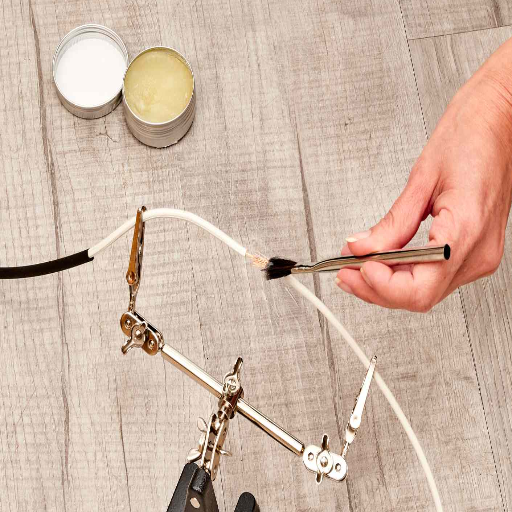
Step 2: Applying Flux to the Wires
Flux plays an integral part in soldering by removing oxidation and impurities from metal surfaces. Select the flux suitable for your particular application, choosing from rosin-based or no-clean. Apply flux sparingly with the brush or applicator directly onto the forced and cleaned wire ends. The flux should cover the whole exposed surface because this promotes good conductivity by minimizing the formation of poor-quality solder joints or cold solder joints. Allow the flux to do its work for a short time, activating its cleaning ability. Do not overapply flux, as excess flux can accumulate residues that may require additional cleaning after the soldering process.
Step 3: Heating the Solder Wire
Heating the soldering iron tip to the required temperature, place it against the wire and the terminal that are to be united. This is the step that produces an excellent bond because both surfaces reach the ideal temperature simultaneously. Keep the iron touching the joint for several seconds to heat it for good bonding; however, contact should be avoided for extended periods, as this could damage the components with heat or even melt the insulation. When the joint is adequately hot, bring solder wire to the heated surface and let it flow freely and evenly into the joint. Solder should cover the wire and terminal surfaces fully and appear shiny in an even layer; this is seen to be a sign of good adhesion. Avoid touching the solder to the iron tip because most time this technique produces weak and unreliable bonds.
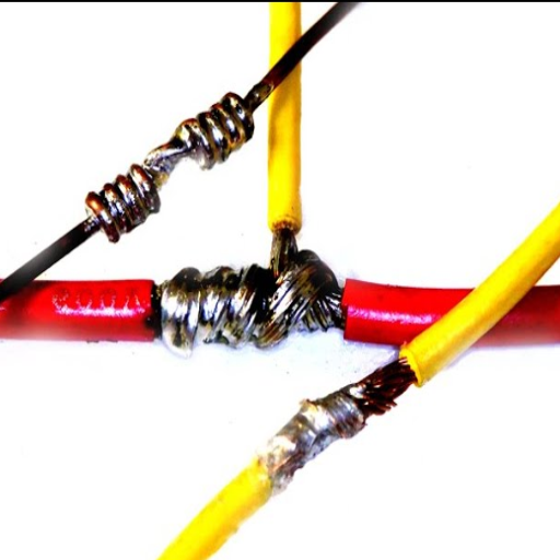
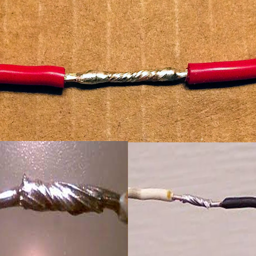
Step 4: Joining the Wires Together
The stripped wire ends should be aligned such that exposed conductors lie parallel and in full contact with each other. Twist the wires firmly together in a clockwise direction to avoid a loose or stray wire that makes a poor splice. After the wires have been twisted, heat the joint with a soldering iron. Let the heat flow through the wires before introducing the solder to the joint (not the iron tip). With good joint heating, the solder will flow and coat the entire surface of the twisted wires, making for a solid bonding connection with as little resistance as possible. After the joint is soldered, examine it for uniformity; a shiny, smooth finish without any spaces is a good indication. Following cooling, cover the joint with heat shrink tubing or an electrical insulator to prevent oxidation or short-circuits.
Troubleshooting Common Soldering Issues
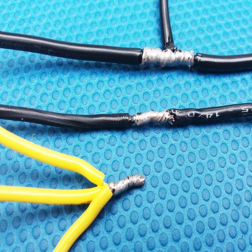
Cold Solder Joints
Cold solder joints cause poor adhesion between solder and components, and hence, they look dull with cracks running through them. To avoid this, make sure the soldering iron is hot enough (350–400°C is generally used for most applications) and the soldering point is being heated enough before applying solder. It has to be reheated and reflowed until the appearance is smooth and shiny.
Excess Solder
When soldering, too much solder can lead to a bulky joint that is unreliable or can risk shorting with nearby components. Carefully remove the excess solder with a desoldering braid or desoldering pump, ensuring that the soldering joint still has enough solder coating.
Insufficient Heat
The solder should flow smoothly, and if it is not flowing smoothly, the soldering iron is not transferring enough heat. Check to see that the tip is clean and well-tinned. Make sure to use an appropriately sized tip so that heat transfer can be maintained. The joint must be heated to an appropriate temperature before the solder is applied.
Burned Components or Pads
Overheating leads to component damage or pad lift. Use a temperature-controlled soldering iron with limited prolonged contact between the soldering tip and the pad. In case of pad damage, use a trace repair kit or wire jumper to re-establish connectivity.
Solder Bridging
Solder bridging occurs when excess solder makes accidental contact between two pins or between two traces and thus causes a short circuit. Such a problem is fixed by removing excess solder with desoldering tools and ensuring that the solder joints are sufficiently separated when re-soldering. A fine-tip soldering iron helps to steer clear of such problems while soldering.
By resolving such common problems, your good soldering practices will ensure the longevity of your electrical connections.
Identifying Poor Connections
Though these indicators may point to loose connections, each will greatly affect the performance and safety of a circuit. Among loopholes for offense are funny acts, wherein the circuit functions sporadically due to unfettered connection, or skyrocketing resistance due to voltage drops and heat pollution. These give away the clues for a distractingly poor connection: dull, cracked, or uneven solder joints caused by either not applying enough heat or incorrectly applying solder. Corrosion or oxidation at the contacts is another common problem, occurring when the connected surfaces are exposed for too long to moisture or some contaminants. Precise measurements are taken through tests on the circuit with a multimeter, such as checking continuity in one path or detecting an abnormal resistance, in order to ascertain the connection. Addressing these symptoms timely manner will save the system from impending failures or hazards.
Dealing with Soldering Mistakes
Some of the common soldering errors that need to be addressed for reliability include cold solder joints, which occur due to insufficient heat or adhesion to the components. Fix it by reheating it with the soldering iron, which should be properly calibrated, and letting the solder flow properly to bond the two surfaces. Excess solder creating bridges between the solder points can be removed with the help of a solder wick or desoldering pump, ensuring that the circuit board is not damaged in the process. Limiting the heat application time and using a soldering iron with temperature control can help prevent overheating components during soldering. Besides, cleaning the work surface with isopropyl alcohol and keeping the iron tips clean will preclude any contamination and thus give good results. To detect and rectify the mistakes in time, one should regularly inspect and test areas suspicious of problems with the help of magnifying glasses and multimeters.
When to Re-solder Connections
The need to resolder connections arises when there is an evident indication of a weak or faulty joint: observable cracks, an absence of conductivity, or when the solder metal is just not adhering to one or both of the components. Other instances that necessitate re-soldering include intermittent electrical connections, loose components susceptible to movement, or circuits not acting according to plan. All these problems may very well arrive due to not having enough heat, too much soldering material, or contaminants cast during soldering in the first place.
Examine the solder joint under magnification to see if re-soldering is needed. Any good solder joint is smooth, shiny, and cone-shaped, while dullness or irregularities, or fractures, big or small, usually spell the problem. Continue with testing continuity with the multimeter. Dusty environments, vibrations, or thermal cycling might cause the previously stable solder connections to begin deteriorating; hence, re-soldering should be considered. Make sure the area is always clean so that the heat and flux can be properly applied with the utmost reliability on the new solder connection.
Advanced Soldering Techniques
It is necessary to understand and mitigate thermal damage while practicing sophisticated soldering techniques. Excessive heat may have an undesirable effect on the components and the PCB (Printed Circuit Board). To prevent thermal damage:
- Use Temperature-Controlled Equipment: Soldering irons should be set to the temperature specified for the materials they are soldering. Thermometers should not display a temperature higher than what is suggested for either the components or the solder type.
- Limit Heat Exposure: Apply heat only for the time necessary to actually affect the soldering. Heat exposure for longer durations will only lead to damage to the more sensitive components or cause the PCB to warp.
- Preheat Complex Boards: Preheat multilayer boards and heat-sensitive assemblies so that less thermal stress is accumulated.
- Check for Heat-Related Issues: Immediately after soldering, evaluate for degradation-prone conditions (discoloration, melted insulation, deformed components); thereafter, replace or perform remedial work on affected areas.
Preventing thermal damage guarantees the reliability of the components and extends the service life of the final assembly.
Soldering Stranded Wire vs. Solid Wire
Because of its structural nature, soldering stranded wire requires a slightly different approach than soldering solid wire. The stranded wires are made by twisting together several thin strands to give flexibility and are used wherever there is expected movement or vibration. Hence, the strands tend to separate during soldering, so the wires must be properly tinned before soldering. Tinning entails the application of an extremely thin layer of solder onto the plurality of strands in order to bind the strands together by way of adhesion, which in turn ensures better conductivity and subsequent ease of handling.
Meanwhile, solid wires consist of a single, rigid conductor. The simple construction is easier to solder and needs no tinning. They are normally used under a stationary condition because rigidity is viewed as a disadvantage under these conditions. However, they are less resistant to mechanical stress and may break when subjected to repeated bending or vibration.
| Wire Type | Structure | Advantages | Best Applications |
|---|---|---|---|
| Stranded Wire | Multiple thin strands twisted together | Flexible, resistant to vibration and repeated bending | Applications with movement or vibration (requires tinning) |
| Solid Wire | Single rigid conductor | Easier to solder, no tinning required, simple construction | Stationary connections, permanent installations |
Depending on the type of wire soldered, preservation of insulation and prevention of damage to the wire require correct heat and avoidance of excessive heating. With stranded wire, an additional step of care must be implemented to ensure solder penetration through all the strands to achieve optimum electrical conductivity, whereas with solid wire, more care must be given to the heating application to produce a good solder joining without heat weakening of the wire. Both wires need to use good solder and flux so that reliable joints are obtained.
Using Heat Shrink Tubing for Protection
To properly isolate the conductivity, I make sure the correct heat shrink tubing is selected to fit snug over the wire or soldered joint. Once the correct size is chosen and slid over the joint, it is shrunk down with an evenly applied heat from a heat gun until fully shaped to the wire. This then forms a permanent seal that achieves insulation, strength, and protection against environmental hazards of moisture and abrasion.
Tips for Professional-Level Soldering
Choose the Right Equipment
Consider purchasing the best-quality soldering iron that has its temperature-adjustable adjustable, guaranteeing a well-soldered joint. Use lead-free solder so that it is environmentally friendly and lasts longer. Consider using a soldering station that comes with a holder and a sponge to clean the soldering iron tip.
Prepare and Clean Components
Before soldering, make sure that the components and surfaces are cleaned and free from oxidation or dirt contamination. Use isopropyl alcohol or a designated cleaner to wipe down the surfaces for optimum conductance. Proper preparation avoids weak joints and ensures the connection is truly strong.
Practice Precision and Heat Management
Place the soldering iron tip on the joint for a couple of seconds before applying the solder. Do not heat anything beyond what is necessary, as this could damage the components. Keep your hand steady, and melt the solder evenly by smoothly feeding it in.
Achieving a strong connection is made easy by pre-tinning wires or the soldering iron itself. This step maximizes heat transfer and creates a strong bond between the wire and solder. Always make sure that each solder joint is examined and looks smooth and shiny; one can always reheat joints that are dull or have uneven spreads.
Use Proper Safety Precautions
Ensure that good ventilation is available in the working environment, employ fume extractors for added safety, and always wear safety glasses. Handle everything carefully, as burns can occur if you come in contact with the hot soldering iron or molten solder. A clutter-free workspace can also help minimize any such risks.
Inspect and Test Connections
Visually inspect each joint once the soldering task is finished to ascertain that no cold or cracked joints are present. Testing can be done using a multimeter for electrical continuity and to check the connection’s stability for professional applications.
Reference Sources
“Information Assistance for Smart Assembly Stations”
“Power Semiconductor and Packaging Trends in Vehicle Electrification”
“Ejectorless Method for Die Attach Pick Up for Cracking Improvement on Thin High-Aspect Ratio Die”
Frequently Asked Questions (FAQs)
What is the type of tin that is best for tinning wires?
Rosin core tin is usually recommended, since flux is produced from it to help grease the solidification of solder on the wires. Based on the solder you purchase for your project, you also need to consider the appropriate solder for your projects if you are working with leaded solder, a solder with restrictions on how it is to be handled.
How does one prepare the wires for soldering?
First, one needs to strip away the plastic coating on the wires. They should be twisted together where two wires join, to ensure security. It is a good idea to clean the wires and make sure the exposed centers of the wires are free from oxidation.
How do you solder wires?
Soldering is a process that consists of many steps. First is turning on the soldering iron and allowing it to heat up. Next, clamp the wires in alligator clips, thus holding them in place. When the iron is ready, apply the soldering iron tip onto the wire, then drop the solder in the joint. The solder melts to create a solder bond when it solidifies.
What can I do to ensure a strong solder joint?
To make sure the solder joint is strong, just apply a small amount of solder so that it runs onto one of the wires. Apply the heated tip of the soldering iron to the joint to transfer heat easily. The application of flux paste will help the solder to be drawn into the joint, making a better connection.
What safety precautions are to be followed when soldering?
Always try to solder in an area where ventilation can be assured to prevent inhalation of fumes. Follow up with washing of hands, especially after working with lead solder. Take care to avoid burning yourself with the soldering iron.
Can a heat gun be used instead of a soldering iron?
While a heat gun may be used for some applications, it is not suitable for soldering wires. A soldering iron is designed to apply heat very precisely to the very tip of a wire to form a strong solder bond.
What happens if the solder won’t stick to the wire?
The case of solder not sticking to the wire probably means the surface of the wire is oxidized. Use cleaning agents and flux to clean the wires thoroughly. If you continue having problems, check that your soldering iron is reaching the right temperature and that you are working with the correct solder for your task.
How do I know that the solder is cold and ready to use?
The solder is shiny and scorching hot for a short time after soldering. Then, after cooling, it becomes dull and solid. Always wait for the solder to be fully cooled before moving the wires so that the connection is cemented well.