








First and foremost, being able to wire a single-pole light switch is an essential skill every home electrician must endeavor to master. Any ardent do-it-yourselfer or initiator in learning electrical work must have a good grasp of wiring this type of switch as a means of working light fixtures in the home. This guide will take you through the process, maintaining safety and clarity at each step. From selecting the right tools to making your connections, you will be taught all you need to become a pro in single-pole light switch installation.
Critical Safety Notice
Always turn off the power at the circuit breaker before starting any electrical work. Use a voltage tester to confirm no power is present. If you’re unsure about any aspect of electrical work, consult a licensed electrician. Electrical work can be dangerous and may require permits depending on your local codes.
Understanding the Single-Pole Switch
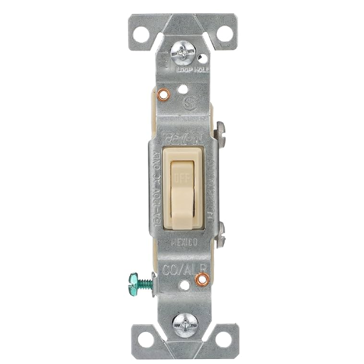
It is the foremost common and simple switch installed in a house. It is meant to control a single light fixture or electrical outlet from one place. A single-pole switch is held distinct from other complex switches, with one terminal for the incoming hot wire and one for the outgoing hot wire going to the light fixture. In fact, it would be the simplest switch, labeled “ON” and “OFF,” that controls lighting from a single location in a simple setup.
What is a Single Pole Switch?
A single-pole switch is a simple electrical switch that controls power to the load from a location. It has two terminals, one for the incoming “hot” wire and one for switching out to the controlled device. Generally marked “ON” and “OFF,” single-pole switches are usually applied in basic lighting or electrical configurations and are easy to work with and identify.
How Does a Single-Pole Switch Work?
Being a switch interrupting or restoring the flow of current in a circuit, a single-pole switch, when flipped to the “ON” position, completes the circuit by internally connecting the incoming “hot” wire to the outgoing one, thus energizing the wiring leading to the device, such as a light fixture or appliance. As the switch is turned to “OFF,” this connection is broken, and therefore electricity ceases to flow.
Simple design translates into great reliability on a single-pole switch. Using a lever inside coupled with the contacts, the switch ensures smooth and positive operation. Typically, when rated for 15 and 20 amps, these switches will have ratings varying from 120 volts to 277 volts in less common applications. In this way, the switch is useful in residential and commercial low-power circuits.
Applications of Single-Pole Switches
Single-pole switch applications are quite numerous and diversified in residential, commercial, and industrial areas, owing to their simplicity and effectiveness:
- Residential Use: Household lighting circuits, including ceiling lights, table lamps, and wall fixtures
- Bathroom and Kitchen Applications: Control exhaust fans or small appliances such as garbage disposals
- Commercial Buildings: Control lighting at individual workstations, small machines, or accent lighting
- Educational and Retail Spaces: Classrooms, small office rooms, or retail store displays
Industry Insight: According to recent industry research, single-pole switches are amongst the most popular electrical items, with millions installed annually around the globe. There has been a surge in demand due to them being compatible with LED technology and other energy-efficient lighting. Even more, some of the latest generation single-pole switches have now come with intelligent features like dimming controls and integration with smart home systems that provide energy savings and convenience to end users.
Understanding Electrical Circuits
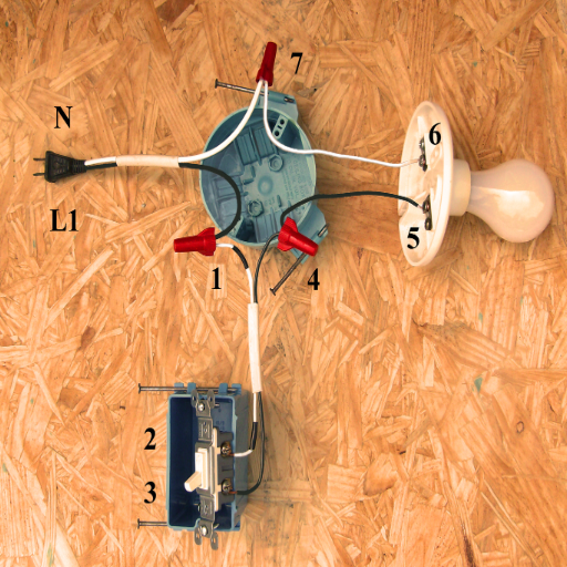
Electrical circuits are just the harnessing of electricity to reach a particular device or appliance. In a very basic form, a circuit will comprise a power source (such as a battery), a set of conductors with which to convey the electricity (wires), a load (like an electric bulb), and sometimes there may be a switch to control the flow. It will operate as an open loop capable of maintaining the current forever, provided that it is closed.
Depending on the nature, the kinds of electric circuits are parallel and series circuits. In series circuits, all components are connected end-to-end, meaning the current passes through each component one after the other. If one particular component malfunctions in a series circuit, the whole circuit is disrupted. On the contrary, parallel circuits connect components across multiple branches that allow current to pass along separate paths, so these circuits would allow functioning in the rest of a branch should one branch fail.
Another basic concept useful in understanding electrical circuits is that of voltage, current, and resistance, which follow Ohm’s Law (V = I × R). Problems with voltage allow the electric charge to flow; a current is an actual flow of electrons; resistance is the opposition to the flow of that current. By knowing these principles, one can both troubleshoot existing electrical systems and safely engineer a good electrical system.
Tools and Materials Needed
A well-outfitted tool kit is the essence of a close encounter with the world of single-pole light switch wiring, raising efficiency and safety during the process:
Screwdriver (Flathead and Phillips)
They remove screws and fasten the switch, along with its cover plate. The majority of switches are designed such that a Phillips screwdriver is applicable, but a flathead could come in handy during sideways adjustments of terminal screws.
Wire Strippers
An insulation layer is stripped off the wires while making these connections. Make sure the stripper is suitable for the wire gauge (commonly 14 or 12 AWG for lighting circuits).
Voltage Tester
Without this, one cannot call oneself a truly safe person when working with electricity. It checks if the circuit is live; wires should be tested every single time before anything is done to them to prevent accidental electrical shock.
Electrical Tape
Useful for insulating wire connections or as extra protection around terminals.
Wire Nuts/Connectors
They act as the connecting and insulating agents for wire ends. Choose an adequate connector depending on the number of wires and gauge to be connected.
Replacement Switch
A single-pole switch should be compatible with your system. Most house circuits are rated for 120 volts and will operate with standard switches.
Additional Required Items
- Cover Plate: Whether a new one or an existing cover plate, it will complete the installation and protect the switch
- Wire Cutter: For cutting wires to length during adjustments
- Needle-Nose Pliers: Best for bending wires into the hook shape needed to attach to screw terminals
- Circuit Breaker Panel Access: For turning off the power and then restoring it after installation. Label circuits ahead of time for clarity
Safety Precautions When Wiring
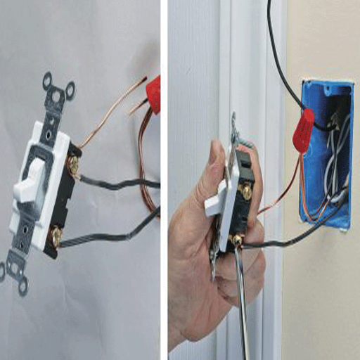
Essential Safety Measures
Up to strict safety standards accidents may occur if a chain of care is disregarded. Key measures are described below as considered most relevant by present industry recommendations and best practices:
Power and Electrical Safety
| Safety Measure | Description | Why It’s Important |
|---|---|---|
| Power Off at Source | Always turn off the power at the circuit breaker panel before commencing work. Use a voltage tester to confirm no current. | Prevents electrical shock and electrocution |
| Use Protective Equipment | Wear insulated gloves and safety goggles to prevent electrical shocks and sparks. | Protects against injury from electrical accidents |
| Check Tools and Equipment | Ensure tools are suitable for electrical work and in good condition. | Defective tools may cause short circuits or inconsistent connections |
| Work in Dry Environments | Never work in damp or moist environments. | Water and electricity create deadly combinations |
Circuit and Code Compliance
- Know Circuit Load Limits: When overloaded, circuit wires heat up and pose a great risk for fire. Always follow electrical codes on maximum amp circuits and devices
- Observe Cable Color Codes: Use standard wiring codes since they will indicate live, neutral, and ground wires so as not to make mistaken connections. Black or red wires usually signify “hot,” white is “neutral,” and green or bare copper is for grounding
- Avoid Overloaded Outlets: Balance electrical load across outlets and circuits, mainly when the demand is high, to avoid excessive temperature or tripping of circuit breakers
- Use GFCI Outlets in Moist Areas: Ground fault circuit interrupters (GFCIs) are a must in places like bathrooms, kitchens, and outdoors
- Stay Up-to-Date with Local Electrical Codes: Learn your area’s building codes and standards for wiring methods that promote safety and security
Emergency Preparedness
- Have A Fire Extinguisher Nearby: Keep one Class C-rated fire extinguisher that is capable of handling electrical fires safely
- Notify Household Members: Let everyone in the house know that the power will be off, especially if you will be doing any electrical repairs or maintenance
How to Safely Turn Off Power
Step-by-Step Power Shutdown Process
- Locate the Main Breaker Panel: Find the main electrical panel of the house, usually in basements, garages, or utility rooms. This is where the circuit breakers, including the main breaker controlling power for the entire property, are located. Ensure free space around for ease of access.
- Switch Off Individual Circuit Breakers: In order to avoid sudden power surges that might occur when power is restored later, the individual circuit breakers are switched off before switching off the main breaker. This is to protect any appliance or device connected to the system.
- Turn Off the Main Breaker: Look for the main breaker, which is usually the bigger switch at the top or bottom side of the panel, and place it in the “off” position. Verify the turn off by observing the light or voltage tester in an electrical outlet.
- Notify Household Members: Let everyone in the house know that the power will be off, especially if you will be doing any electrical repairs or maintenance. This increases safety and reduces confusion.
- Restore Power Safely: When restoring power, switch on the main breaker first, and then turn on each circuit breaker one at a time. This prevents overloading or may hurt the appliances that are being energized.
Steps to Wire a Single-Pole Light Switch

Step 1: Turn Off Power
Locate the circuit breaker for the light switch and switch it off. Confirm by testing the voltage that no power is present.
Step 2: Remove the Old Switch
Remove the switch cover plate by unscrewing it. Remove the existing switch by unscrewing it. Pull it out very gently to access the wiring.
Step 3: Check the Wires
Check which wires were connected to the old switch. Usually, there is a black “hot” wire, a white “neutral” wire in some cases, and a bare or green-colored ground wire. Make sure the wires are intact.
Step 4: Preparing the Wires
Once the wires are prepared to be installed, power at the breaker should be turned off if it is not already. A voltage tester shall be used to ensure that no voltage exists. Now strip about ¾ inch off the ends of each wire with wire strippers. Identify the hot wire—black or red usually; identify the neutral wire—white usually; and identify the ground wire—green or bare copper usually. If old or frayed, trim the wire ends, then strip the wire insulation to bare the wire again. Lastly, either straighten the stripped wire ends or grab them with needle-nose pliers to make small hooks for fastening securely to the switch terminals.
Step 5: Connecting the Wires to the Switch
Wire Connection Sequence
- Attach the Ground Wire: Start by attaching the ground wire (green or bare copper) to the green grounding screw on the switch. It should be very tight to ensure an excellent connection.
- Attach the Neutral Wire: If your switch needs a neutral connection (e.g., for smart switches), connect the white neutral wire to its designated terminal. Some regular switches need no neutral wire; in this case, cap the wire securely with a wire nut.
- Attach the Hot Wire(s): Identify the hot wire, which is usually black or red. Attach it to the terminal marked common or the one designated for power input. In a three-way switch, attach the other traveler wires (commonly black or red) to the traveler terminals. Make sure to carefully follow the wiring diagram for the switch.
- Ensure All Connections Are Tight: Once all wires are connected to the corresponding terminals, make sure the screws are tightened well. Do not leave any wire exposed outside the connection terminals.
- Check Everything Again: Verify all connections for their correctness and fasten securely. Arrange the wires nicely in the box so as not to pinch or damage them.
Step 6: Fasten the Switch
Very carefully push the wires back into the electrical box and fasten the new switch into the box using the screws.
Step 7: Attach the Cover Plate
Put the plate over the switch and fasten it down with the screws.
Step 8: Power Restoration and Testing
Turn the breaker switch back on and check for proper operation of the switch.
Testing the Connection
Once the installation is complete, ensure all wires are fully secured and tightly connected. Follow the steps below to test the connection.
Testing Process
- Restore Power: Turn your circuit breaker or power source on, giving power to the circuit.
- Check for Functionality: Operate the switch to verify that it works correctly. For a simple on/off switch, it should allow us to control or dim the fixture or device that is connected.
- Inspect for Issues: Anomalies should be observed in the switch operation, such as flickering lights or heat coming from it, a burning smell, or a humming noise. This may indicate a potential wiring problem.
- Confirm Safety: If these issues are all absent, make sure that the switch plate is fastened firmly so that no wires or components are exposed. If there is any fault, turn off the main power to check the wiring again or call for professional assistance from an electrician.
Final testing guarantees that your installation is safe and executed properly, thereby guaranteeing a very strong connection. Always put safety first and promptly deal with any issues that arise.
Using Protective Gear While Wiring
The primary consideration when dealing with electrical wires is to get ready for safety:
| Protective Equipment | Purpose | Safety Benefit |
|---|---|---|
| Insulated Rubber Gloves | Protect against electrical shocks | Essential for repair or maintenance work |
| Safety Goggles | Protect from sparks or debris | Shield eyes from accidental short-circuits |
| Non-conductive Footwear | Rubber-soled shoes prevent grounding | Prevents electrical source grounding |
| Flame-resistant Clothing | Minimize burn risk from arcs or sparks | Reduces injury from electrical incidents |
Always check that your safety equipment is approved for use by safety authorities and examine the equipment for any damage before use. Any wiring work accompanied by proper protective gear and caution produces no accidents.
Troubleshooting Common Issues
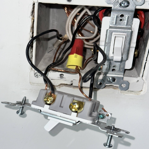
Identifying Wiring Problems
Early recognition of wiring problems keeps a person from exposing themselves to potential hazards and spending loads of money on repairs. Based on expert advice, common symptoms and solutions to consider are:
Common Electrical Issues and Solutions
Flickering or Dimming Lights
Cause: A loose wire or overloaded circuit may cause this.
Solution: Examine the fixtures for proper connection and workload allocation between circuits.
Circuit Breakers Trip Very Often
Cause: Usually overloaded or shorted circuits.
Solution: Find out which appliances are causing excessive load and make adjustments. Ensure there are no broken wires.
Warm or Discolored Outlets and Switches
Cause: Loose wiring, overloaded outlet, or faulty appliance.
Solution: Shut off the power immediately and solve the problem to avoid fire incidents.
Buzzing or Crackling Noises
Cause: Dangerous wiring issues, such as loose connections.
Solution: Stop using the outlet immediately and get professional help.
Burning Smell or Scorch Marks
Cause: Overheating or possible fire incidents.
Solution: Switch everything off using the main power switch immediately and call an electrician.
Fixing a Non-Responsive Light Switch
When dealing with an unresponsive switch, follow this troubleshooting sequence:
- Check the Light Bulb: Verify if it needs changing
- Check the Circuit Breaker: Determine if it has tripped
- Inspect the Switch Wiring: Look behind the switch for any loose wiring or connections, after making sure the power is switched off in the breaker box for safety
- Call a Professional: If you cannot find or fix the problem, a licensed electrician is the one to call for professional assistance
General Troubleshooting Approach
When troubleshooting wiring problems, begin by considering symptoms of the problem, such as flickering lights, breakers tripping, or outlets not working. For flickering lights, begin with the bulb and socket, as loose or faulty bulbs are usually the source of the problem. In case breakers are tripping often, then check for overload and short circuit in the particular circuit, and rearrange the load if needed. Outlets that refuse to operate may have the GFCI option tripped or could have loose connections inside the outlet. Safety first: turn off the power to the place you are going to inspect or repair. If the trouble persists or is too complicated, you may wish to call in a licensed electrician for a safe and workable solution.
Understanding Electrical Safety
Electrical safety is very important for the prevention of incidents and injuries as well as damage to property. Here are some concise answers to the core principles based on common information found in several leading sources:
Core Safety Principles
- Turn Off Power: Always shut off the power supply from the main circuit breaker before starting any electrical work. Verify with a voltage tester to make sure the circuit is not energized
- Proper Tools and Equipment: Perform electrical tasks with insulated tools and equipment intended for electrical work. This will minimize the hazards of electrical shocks or damage
- Avoid Circuit Overloading: To avoid overheating or fire hazard, match the power needs of appliances to their compatible outlets
- Know Your Wiring and Connections: Make sure to have good connections and use an appropriate type of wire for the application. Faulty wiring ranks at the top of all malfunctions and hazards
- Keep Children Safe: Install safety outlet covers or safety plugs to prevent children from touching live electrical parts
- Know Your Expertise: Know your limits. In complex or high-risk jobs, ask for or hire the services of a licensed electrician, so that mistakes may not only be costly but also dangerous
Final Safety Reminder
By working along these lines, you shall make for a safer environment and cut down on the risk involved with electrical work. Abiding by professional guidance and local codes holds the key to long-term safety and compliance. Please regard all safety precautions and use tools that are designed to work with electrical applications, so you can complete the project with ease. For large or complicated electrical projects, it is best to seek professional help.
Generally, their versatility, affordability, and ease of use place single-pole switches in a club of the essential components of electrical work in many settings. Another easy installation and maintenance consideration is single-pole switches. Single-pole switches are made for circuits where lighting or appliances are controlled at one location only, so they are perfect for a one-room light or small appliance. When installed correctly and following electrical codes, it guarantees years of safe and durable operation.
Reference Sources
“Verification of Electromagnetic Essential Connection”
“Design of EV Go: Kart Electrical System”
“Outdoor Lighting Design Process Optimization”
Frequently Asked Questions (FAQs)
What is single-pole switch wiring?
Single-pole switch wiring is the electrical connections designated for a single-pole light switch used to control one light fixture or a group of fixtures from one location. These configurations generally comprise insulating a hot circuit wire to the switch and a white wire for neutral connections, and a ground wire for safety purposes.
How do I wire a single-pole light switch?
Ensure to turn off the circuit breaker for safety before wiring a single-pole light switch. One of the screw terminals of the switch should be attached to the black colored wire, used as a hot wire; the other terminal should then be connected to the white wire if necessary. For safety reasons, the grounding pigtail should be linked to the switch’s grounding screw.
In an electrical box made of metal, can I install a single-pole switch?
Yes, the single-pole switch can be installed in a metal electrical box. The metal electrical box must be connected to the circuit ground for safety. This entails attaching the grounding wires with a wire connector to the grounding pigtail in the box.
What’s the difference between a regular light switch and a dimmer?
A regular light switch operates to simply turn the light off or on, while a dimmer is capable of adjusting the amount of brightness being emitted. When wiring a single-pole dimmer, the connections will be somewhat similar to wiring a single-pole dimmer switch, although a certain type of dimmer might require additional wires.
How do I identify the loop in single-pole switch wiring?
The switch loop in single-pole switch wiring normally has the single switch in control of the fixture. The hot wire goes from the power source to the switch and then returns from the switch to the light fixture. Identifying the loop requires tracing the wires connected to the switch and the light and making sure they are wired correctly.
What should I keep in mind about safety while wiring a single-pole switch?
First, switch off the circuit breaker to avoid any possibility of shock. Use a voltage tester to check if wires are live or not. Connect the grounding wire to the naked grounding wire of the supply cable, and make all other connections very secure to avoid short circuits.