The 500-Watt Linear CB Amplifier is a revolutionary gadget that can bring great changes to the lives of hobbyists and professionals alike, aspiring to extend their communication abilities. This amplifier boosts the power and clarity of CB radio transmissions to twenty-five watts in the most favorable atmosphere for operation. Whether it is a rough, bumpy terrain, steady long-distance communication, or just enhancing one’s radio for better signal reach and sound clarity, it is good to know about the working and benefits of the 500-watt amplifier. The article shall dwell upon the working principle of the device, the technical merits, and factors in determining the amplifier best suited for one’s particular working needs. Find out how this powerful equipment will change your experience with his radio while staying within regulatory guidelines and established industry standards.
Understanding Linear Amplifiers
The linear amplifiers are those electronics meant to amplify radio frequency signals, with the waveform characteristics in their original form. They operate in the linear region of a performance curve of an amplifier, thus ensuring minimal distortion of the signal. These amplifiers have their application areas wherein the actuality of a signal is critical: amateur radio, broadcasting, and communication systems. Things to consider for any given linear amplifier include power levels, output frequency range, and efficiency, all of which impact how well an amplifier will perform with systems and how well it meets standards for those systems. Reliable models are built to perform as regulatory standards dictate for safe and compliant operation on assigned frequency bands.
What is a Linear Amplifier?
In essence, a linear amplifier is an electronic circuit designed to cause an increase in the amplitude of the input signal, without alteration to its original waveform and hence the signal quality. The amplifier works only for a limited range of frequencies, and it is designed to produce an output that is proportional to the input to minimize distortion. These tend to be employed in RF systems, audio, and telecommunications, where the signal’s integrity is paramount. In simple terms, a linear amplifier uses either transistor or vacuum tube operation in the linear portion of that device to amplify the signal. Because accuracy is paramount, in order for these amplifiers to properly do their job, they must possess a set of characteristics such as gain, bandwidth, efficiency, and linearity in ideal values.
Advantages of Using a Linear Amplifier
High Signal FidelityGiven that linear amplifiers amplify signals without subjecting them to significant distortion, they maintain a high degree of signal integrity between their input and output. Hence, all applications for which an audio, radio-frequency, or other analog signal must be reproduced with exactness will require them.
Broadband CharacteristicSuch amplifiers operate well with a wide range of frequencies, thereby assuring a consistent performance in applications such as communications, broadcasting, or instrumentation.
Low Levels of DistortionBecause they can operate in the linear region of their gain characteristic, linear amplifiers are characterized by very low harmonic and intermodulation the ingredients that contribute to signal degradation in audio and RF systems.
Compatibility with Complex Modulation SchemesLinear amplifiers are ideal for advanced modulation schemes used in modern telecommunications, such as QAM, to ensure accurate transmission and decoding of data.
Versatility of ApplicationsFrom professional audio equipment to laboratory instruments and RF transmitters, their ability to handle high-signal-quality applications makes them very versatile across technical disciplines.
For applications where high precision is required, little modification of the input signal can be tolerated, and the application may need to be altered reasonably straightforwardly in the short run, linear payers are secured in parametric technology systems for which they form the basis of integration.
How Linear Amplifiers Work
Given an input Electromagnetic Signal (EM signal), an ideal linear amplifier should increase the amplitude whilst retaining waveform integrity so that an output signal can be a mere scaled copy of the existing input. This process is carried out by means of cascading amplifiers, which have been designed to serve a specific purpose. First, the signal will be fed into a pre-amplification stage in order to set the voltage to the required level of processing. After this operation, the signal proceeds to the main stage of amplification, which, between the transistors or operational amplifiers, is chosen to offer the most linear action possible.
The amplifier operates best in its linear region for minimal distortion; any overdrive or saturation creates distortion. Gaining stability is often enforced by feedback, which also cuts down on non-linear distortion and enhances the amplifier’s performance. The power supply must also remain steady, or noise could be left in the circuit, impacting the accuracy of the measurements. At this point, the output signal will be directed to the load connected to the system, such as speakers, antennas, or other electronic systems.
Linear amplifiers maintain performance by preserving accuracy and preventing signal degradation during operations requiring high-fidelity and accurate applications.
Features of the 500 Watt Linear CB Amplifier
| Feature | Description |
|---|---|
| High Power Output | Consistent output of 500 watts enables strong signal transmission over great distances. |
| Efficiency | Optimized for power efficiency to minimize heat dissipation without compromising output. |
| Signal Clarity | Provides minimal distortion and high-fidelity signals that support communication requiring exactness and clarity. |
| Durability | Designed with high-quality components. These ensure the amplifier’s ability to withstand prolonged hours of use and harsh operating conditions. |
| Compatibility | Compatible with an extensive range of CB radio systems, it may thus be installed without requiring any additional alteration. |
| Thermal Protection | Equipped with cooling features and protection against overheating, especially under continuous operation. |
| Easy to Use | Includes simple controls and displays that make it easy to operate, even for less experienced users. |
This set of features renders the 500 Watt Linear CB Amplifier a reliable choice for those users in need of irrefutable performance and trustworthy operation.
Power Output and Efficiency
The 500-Watt Linear CB Amplifier is a high-power output device built to robustly transmit signals across long distances. With an emphasis on high efficiency, it ensures greater energy optimization through minimized power losses during operation, thus contributing to the overall high performance of the amplifier. The amplifier has a rated 500 watts at peak and is hence the right choice for high-demand applications, while adhering to all FCC regulations. High-end Class AB amplification methods are used, striking a balance between linearity and efficiency to allow the signal to propagate clearly and to reduce interference. Such a design improves the output quality and allows for extended use without wearing the equipment out or overheating excessively, thus cementing the reliability of the amplifier for communications, be they professional or recreational.
Frequency Range: HF, SSB, FM, and CW
The indicated HF, SSB, FM, and CW frequency spectrum is presently usually used in several areas of radio communications. High frequency (HF) between 3 and 30 MHz is available for great communications; skywave propagation occurs at the ionosphere level. Single-sideband modulation is a refined form of amplitude modulation in which one sideband is filtered out. Hence, SSB is more spectrum-efficient and is used in amateur radio and aviation for clarity and efficiency of power. FM offers the best quality audio signals in VHF frequencies, generally from 88 to 108 MHz for broadcast and 30 to 300 MHz for communications like two-way radio. Morse code style of CW, due to its narrow bandwidth and hence long-range abilities, is advantageous for low-power and emergency operations. These frequency modes are supposed to fulfill different requirements of operational needs, catering to versatility and challenges due to performance.
Compatibility with CB Radio Equipment
The CB radios are supposed to operate in a frequency range of around 27 MHz, usually from 26.965 MHz to approximately 27.405 MHz, transmitted via AM and SSB. Any machine or device that will interfere with the CB signals must follow the given frequency range in the USA and adhere to the transmission mode specified by the governing body. Therefore, new CBs are designed with a few features laid down by the FCC to make the devices compliant and work with others working within the same band.
Dual-band or even multi-band radios that include CB and HAM frequency ranges are pretty much necessary for cross-device compatibility. Where transmitting outside of the CB frequency range, in particular in HAM bands, is concerned, FCC regulations require a proper license. Another important feature is antenna choice- CB radios need antennas that are specifically tuned for the 27 MHz range to get the very best from them in terms of performance and signal clarity. With these technical parameters understood, seamless integration and use of CB radio equipment can be realized.
Installing Your 500W Linear Amplifier
Installation of the 500W linear amplifier involves steps that require care to ensure safety and proper functioning without any risk or hazard:
PlacementPut the amplifier in a well-ventilated location so that it can never get overheated. Do not place it close to heat sources or in confined spaces.
Power ConnectionThe amplifier must be connected directly to a DC source of power that is of good quality. The power cables must be rated to handle the current draw that the amplifier will use. Connection must be made securely to the positive and negative terminals.
Antenna MatchingDesign and tune your antenna to operate within the working frequency band of the amplifier, possibly even requiring the use of an antenna tuner to fix any impedance mismatch.
Radio ConnectionUse a high-quality RF coax cable with its connectors tightened firmly to avoid signal loss between the RF input of the amplifier and your CB or transceiver output.
GroundingThe amplifier must be grounded properly to minimize electrical interference and improve safety. Use a solid grounding wire connected to a good earth ground.
Operational TestingFollowing the installation, go ahead and test the amplifier at low power settings, ensuring the clarity of the signal and that it is functioning correctly. Make observations about interference or any signs of excessive heating.
Following this set of steps can provide for a reliable installation while safeguarding your equipment from damage. Always refer to the user manual and comply with local laws guiding amplifier usage.
Choosing the Right Antenna for Optimal Performance
In any communication or broadcasting system, it is of utmost importance to select the appropriate antenna. Several factors must be considered:
Frequency Compatibility antenna should be compatible with the frequency range of your system. Considerable signal loss and poor performance result if the antenna is operated outside its specified range.
Gain and Directivity are the quantities of signal energy transmitted from an antenna in a particular direction relative to an isotropic source. It is expected that a higher-gain antenna will allow better coverage area because of increased signal quality in a certain direction.
PolarizationEnsure that the polarization of an antenna (vertical, horizontal, or circular) is compatible with that of your transmitter and receiver, maximizing signal alignment and helping to oppose losses.
Environment and Mounting ConditionsAssess the physical environment where the antenna is to be positioned. Obstructions, distance, atmosphere, and the like are significant parameters in antenna selection. The operational requirements should dictate the indoor or outdoor suitability and type of mounting, such as rooftop or wall mounting.
An impedance antenna should match the impedance of your transmitter or receiver, usually 50 ohms, so that minimum reflection and maximum power transfer take place.
Beamwidth the case of directional ones, the beamwidth is considered with reference to how concentrated the signal transmission will be. Point-to-point communication with a narrow beamwidth or a wider beamwidth for wide-area coverage may be considered.
Choosing an antenna that fits these parameters thus guarantees optimal, reliable transmission and reception of signals, hence improving overall system efficiency. For detailed specifications, consult manufacturer datasheets and technical reviews.
Installation Process and Best Practices
An antenna must be installed correctly so that it may give the best performance and reliability to the system. Selection of an installation site should ideally be done so that “Line of Sight” is maintained with the intended coverage area or communication point, so there are minimal obstructions due to buildings, trees, or any other physical structure. Mount the antenna on a stable, non-conductive structure or pole at the recommended height specified in the manufacturer’s manuals.
Use a signal strength meter or an alignment tool while aligning the antenna. Some slight alignment errors can cause a massive degradation in the signal performance where high frequencies are involved. For weatherproofing, it is best to use weatherproofing materials like UV-resistant covers for coaxial cables; all connector shields should be given an application of dielectric grease and accordingly sealed to seal out water.
Grounding is one of the essential safety provisions; when grounded correctly, it protects the antenna, the equipment connected to it, and persons from lightning strikes and static increases. Standard grounding procedures are to be observed, including the use of surge protectors and grounding rods driven into hard earth.
Finally, keep a comprehensive system performance test after installation to check signal strength, coverage, and data transfer efficiency under actual working conditions. Regular maintenance is recommended to keep peak performance ongoing, which includes checking the connectors, cable integrity, and antenna alignment.
Troubleshooting Common Installation Issues
Weak or No SignalWeak or no signals usually come from improper antenna alignment, damaged cables, or a barrier in the signal path. So, first of all, check that the antenna is directed according to the manufacturer’s instructions and that no shrubs or tall buildings block it. Inspect all cables and connectors to see if they show any wear, damage, or are improperly installed.
Interference or Disruption of SignalInterference could be caused due to electronic gadgets in its vicinity, intermodulation noise, or two signals overlapping in the frequency band. Identify the source of interference using a spectrum analyzer and change the frequency settings of your equipment, if possible. Shield cables properly and keep a safe distance from any high-power electronic devices.
Dropped Connection Connection dropouts are most often caused by power fluctuation, hardware faults, or some level of improper software configuration. Check that the power source gives a constant voltage and that all hardware devices are working, mainly surge protectors and power insulators. Upgrade device firmware and check the network setting configurations, such as IP addresses and channel bandwidth.
Slowing Down Data TransmissionUnlike what one expects with data speeds, bandwidth reduction, heavy network flow, and obsolete hardware show these characteristics at slow speeds. Monitor bandwidth usage for obstruction and consider a hardware upgrade to higher bandwidth models, such as routers or antennas. Network system optimization should be carried out by ensuring all devices run on the basis of existing standards and protocols.
Environmental FactorsExcessive weather effects, say heavy rain or winds of great force, could hamper performance. Weatherproof the systems. The hardware used as mountings should also be firmly secured. It is good practice to continuously monitor environmental conditions, and whenever adverse weather impinges on the system and its performance, adjust the system parameters accordingly.
Every problem must be solved through systematic troubleshooting, as described by the manufacturer’s instructions and industry best practices. Document all tests and correction actions to assist in further diagnostics.
Using Your 500 Watt Linear Amplifier Effectively
Power Supply Requirements
Connect the amplifier to a steady power supply of adequate capacity. Ensure the voltage and current comply with the operational requirements of the amplifier in order to prevent damage or degradation of performance.
Proper Ventilation
Use the amplifier in a space that allows proper ventilation while preventing excessive heating. Ensure nothing impedes the free airflow around the unit; if the unit is running at its full capacity most of the time, consider an external cooling means.
Signal Integrity
Use cables and connectors capable of withstanding the signal loss except for interference. Regularly inspect connection points to confirm that they are securely fitted against corrosion or damage.
Load Management
Ensure the amplifier is applied to the proper load as per impedance as given in the manual. An incorrect load may cause inefficiency or even failure of the amplifier.
Routine Maintenance
If dust has gathered, if a connection has become loose, or if wear has taken place in the amplifier, it should be addressed. Clean and repair the unit for its best working condition, as well as to extend its lifespan.
Operating Modes: SSB, FM, and CW Explained
Single Sideband (SSB)
One of the more efficient modes of communication is SSB, which is widely used in amateur radio as well as by professionals. The classic AM signal has two sidebands-waves of the same shape and amplitude, upper and lower sidebands. In SSB, one of these sidebands (upper or lower) is suppressed, along with part or sometimes all of the carrier, thereby saving on bandwidth. Since this mode requires lower power usage and causes less interference, it increasingly proves useful for long-distance communications. Due to its clarity and efficient usage of limited bandwidth, SSB is a very good mode of transmission for voice signals.
Frequency Modulation (FM)
FM modulation is used for high-fidelity audio productions like radio broadcasting and local communicative applications. FM varies the frequency of the carrier wave directly in proportion to the amount of the signal. This mode of modulation offers advantageous resistance to noise and interference and produces audio signals that are clear and reliable. However, FM uses a lot of bandwidth as compared to SSB, thus becoming inefficient while communicating over long distances through a congested bandwidth.
Continuous Wave (CW)
CW is the backbone of amateur radio. Very few modes are as simple and efficient in Morse code communication. In fact, information is encoded by turning the carrier wave on and off, a method that requires considerably less bandwidth and power to pass along a message. Because of their narrow bandwidth, CW signals travel long distances and are the most suitable under adverse propagation conditions. For operators, CW is prized for its reliability and the skills required to effectively use it. Therefore, CW remains the basis for emergency and hobby communications.
Maximizing Range with Your Amplifier
Optimizing your amplifier’s range covers much ground, including everything from power considerations to proper antennas to signal losses. First, with regard to power levels, an amplifier should be kept within its rated levels either to prevent distortion from occurring or to be damaged, thus ensuring keen efficiency. The power derived from the amplifier should be compatible with the transceiver and antenna so that performance can remain consistent.
Secondly, the antenna can be most instrumental. Because a high-gain or directional antenna directs energy in a specific direction, it can increase the range of signal transmission. Placement of the antenna, along with its height and orientation, will equally determine whether it is free from obstructions and able to enjoy unimpeded line of sight transmission.
Lastly, you want to minimize any signal loss in your setup. Choose high-grade coaxial cables with low attenuation, and make sure that all connections are very secure and weatherproof. Such measures allow you to minimize interference from nearby electronic devices and fine-tune impedance matching between components for maximum signal strength. These two aspects, coupled with its own amplification and EMI shielding capabilities, greatly contribute to better amplifier performance and range.
Monitoring and Adjusting Signal Strength
To maintain reliable communication and maximize performance, monitoring and adjusting signal strength must be done productively. Use signal strength meters and analyzers to measure and graph the quality and intensity of the signal in real time. These tools provide very accurate data with regard to power level, interference source, and presence of noise.
Once the measurements are taken, determine the places where signal degradation or interference is occurring. Typical adjustments include moving the antenna to improve line-of-sight or adjusting the antenna orientation to face the direction that gives the strongest signal. In the case that interference is spotted from neighboring devices, you might want to look at the selection of a less congested frequency band or the addition of filtering.
A little tinkering with gain settings can ensure a perfect balance between output power and noise or distortion. To set it best, be in small increments each time while simultaneously monitoring the signal readings, until it manifests the best possible arrangement. It is also important to periodically check the signal conditions and reassess the instrument arrangement to make sure it retains performance and adjusts with environmental factors. In this way, fighting undesired alteration of amplitude from readings with gain adjustments provides the most efficient combination for maintaining signal strength.
Popular Brands and Models of 500 Watt Linear Amplifiers
Ameritron AL-811H. It is, indeed, a well-regarded model for its dependability and user-friendliness, housing four 811A tubes and delivering power steadily.
Elecraft KPA500Considered especially efficient and compact in design, the KPA500 yields an output of 500 watts, while also giving advanced thermal protections and automated operations.
Tokyo Hy-Power HL-1.5KFX. produces slightly more than 500 watts and is often preferred by expert users for its clean signal output and excellent build quality.
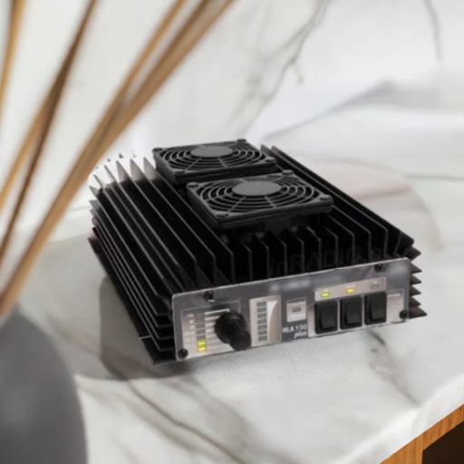
RM Italy HLA 300 Plus VHF/UHF. If flexibility is what you want, this amplifier supports multiple bands and provides reliable performance of up to 500 watts in a sturdy, compact package.
Each one of these is well-known for performance and longevity, accommodating different user needs and settings.
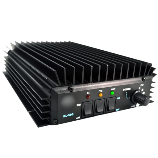
Overview of RM KL Series Amplifiers
The RM KL series amplifiers are popular for their performance, compact design, and universality in radio communication applications. Designed mainly for the HF, VHF, and UHF bands, these amplifiers aim to serve the needs of both amateur radio operators and professionals who require dependable and efficient signal amplification. The RM KL series comes with the protection circuit built in so that it is rugged, easy to install, and widely compatible with transceivers.
Models such as the RM KL 203 and RM KL 300 are given special consideration for their excellent signal clarity and low distortion. The RM KL 203, for example, can pump out power at levels of up to 100 watts, giving sufficient signal amplification for mobile and base station setups. The RM KL 300, on the other hand, increases this operation, offering a power rating of up to 300 watts for those who demand high power ratings. In the interest of user convenience, most of these amplifiers come equipped with a cooling system that gives dependable operation over long periods.
The RM KL series is well thought of because of the uniqueness created between affordability and performance, making it a preferred choice for both amateurs and professionals. Every model in the series is capable of meeting stringent standards, thereby guaranteeing long-term stability and consistent output under differing conditions.
Comparing Moonraker and Other Brands
For me, Moonraker stands out when cost-effectiveness and performance reliability are compared across other brands in the market. Their equipment goes through rigorous manufacturing standards that ensure consistent performance even under the harshest of working conditions. While others may concentrate on niche features or costliness in a bid to price their equipment out of reach of the common man, Moonraker has taken a position that keeps the equipment affordable. This balancing act is reflected in the RM KL series, which guarantees good performance with fairly practical features like integrated cooling systems, something that cannot be taken for granted on competing equipment at this price level.
The 500-Watt Linear CB Amplifier represents a significant investment in your communication capabilities, offering enhanced power, clarity, and range for both professional and recreational use. By understanding its features, proper installation techniques, and optimal operating practices, you can maximize the performance and longevity of your amplifier while maintaining compliance with regulatory standards.
Reference Sources
Frequently Asked Questions (FAQs)
How can a 500-watt linear CB amplifier compare to a 100-watt linear amplifier?
While a 100W amplifier sufficiently provides output for most ordinary uses, a 500-watt linear CB amplifier greatly boosts the power output and allows better performance in signal clarity and distance. This power advantage is useful for an amateur radio technician trying to efficiently function in the HF bands.
What kind of antenna do I need for a 500-watt linear amplifier?
High power brings greater responsibility! Great care has to be taken in ensuring proper installation of a power amplifier into a CB transceiver. With the 500-watt linear amplifier, it would be advisable to install a heavier-duty antenna with it to cope with the increased power output. A proper CB antenna compensated for the additional dB rating is essential in both transmitting and receiving signals. A high-gain vertical or directional antenna would be best.
Is it good to use a 500-watt linear amplifier with a portable CB?
Absolutely! A 500-watt linear amplifier can be a part of your portable CB setup. You must first ensure the power supply will support the amplifier, which usually means a 24V unpackaged power supply. Also, take weight and size into consideration for the portable setup.
What is the purpose of having a switch on the 500-watt linear amp?
Generally, a 500-watt linear amplifier will feature a power control switch for manual operation, thus enabling the user to either engage or disengage the operating boost at will. Being able to instantly regulate power output under varying operational parameters is vital for keeping the power output within rated values, thereby minimizing unnecessary stress on the equipment and prolonging its life.
How do you set up a 500-watt linear amplifier with an HF transceiver?
For setting up a 500-watt linear amplifier with an HF transceiver, connect the output of the transceiver to the input of the amplifier through proper coaxial cables. Ensure that the amplifier is kept grounded while providing an AC power supply of ample rating. This setup will assist you in further developing your transmission capability over the HF bands.
What kind of modulation can I use with a 500-watt CB linear amp?
A 500-watt linear CB amplifier is in the range of modes of modulation from AM, SSB, to FM. Differences in the modes of transmission can make a transmission scheme more or less viable for performance and transmission range: thus, SSB is a more frequent mode for long-haul links in amateur radio because it is more efficient in the way it uses its bandwidth.
What advantage does a solid-state 500-watt linear amplifier have?
A solid-state 500-watt linear amplifier is considered to be reliable and requires hardly any maintenance. Being totally different from a tube-based amplifier, it provides a steady performance without warm-ups or component replacements. It is the perfect choice for casual Amateur Radio Operators and those who take it seriously.
Can a 500-watt linear amplifier be used for satellite communication?
Technically, a 500-watt linear amplifier can be employed for satellite communications, taking into account the satellite operations’ requirements, such as modulation type and frequency bands. Moreover, the use of a rotator may be a necessity to effectuate satellite tracking for optimum alignment with the satellite’s position.