








When installing a 60-amp subpanel, one of the most crucial factors in the safety and efficiency of an electrical system is the proper wire size. Incorrect wire size might cause overheating, voltage drops, and even potential fire hazards. Therefore, it is necessary to observe proper guidelines and electrical codes. The article will give you a detailed and basic introduction to the wiring requirements of a 60-amp circuit, including a discussion about the roles played by wire gauge, distance, and ampacity in size determination. You can be a homeowner doing a DIY project or a professional wanting a refresher; this guide will provide you with the necessary knowledge to make the right decisions and not violate safety regulations.
Introduction to 60 Amp Sub Panels
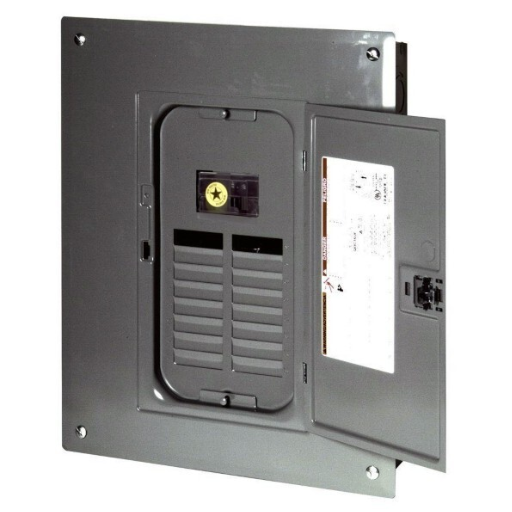
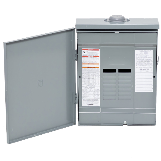
The term “60 amp sub panel” refers to a secondary electrical panel capable of handling power of up to 60 amps that is installed to distribute the electrical current from the main panel to certain circuits or locations. Such panels are usually installed in workshops, garages, or extensions for the purpose of supplying power to equipment or devices that require more energy consumption than regular household devices. Before proceeding with a 60-amp sub-panel installation, it is very important to verify that the main panel has adequate capacity and all parts, like the breaker, feeder wires, and sub-panel, must be rated for 60 amps. Electrical codes must be strictly followed during installation, and this might require a permit or inspection by an authorized electrician.
What is a 60-amp subpanel?
A 60-amp subpanel is a type of electrical panel that serves as a secondary source of power and allows for the addition of circuits. It is most commonly seen in situations where power is to be supplied to areas like garages, workshops, or sheds. The device has the ability to accommodate 60 amps of current and is usually connected to the main panel through a double-pole breaker and feeder wires that have a 60-amp rating. The subpanel’s main purpose is to distribute electrical circuits, thus giving a proper and organized control of electrical loads in places where there is a higher consumption of energy. It is necessary that the installation is done properly and that it adheres to the local electric codes, which include the grounding and neutral bars, proper wire sizing (generally, 6-gauge copper or 4-gauge aluminum), and obtaining the required permits or inspections.
Importance of Correct Wire Size
Choosing the right wire size is one of the most important aspects of electrical installations for the same reasons: safety, efficiency, and code compliance. The wire gauge is the one that decides the current-carrying capacity, and thin wires are connected to a lot of risks, such as overheating, voltage drops, or even electrical fires. As an illustration, a 60-amp circuit would usually need 6-gauge copper or 4-gauge aluminum wires. Depending on the distance, larger wire sizes may be required to counteract the voltage loss across the span. So, compliance with the National Electrical Code (NEC) and utilizing suggested wire sizes for specific amperage ratings becomes crucial in eliminating hazards and keeping the electrical system’s integrity intact. Also, proper wire selection plays a part in efficient energy distribution, thus minimizing power loss and circuit performance reliability. Always check local codes, professional guidelines, and certified electricians to get the wire size requirements confirmed for any project.
Applications of 60 Amp Sub Panels
The 60-amp sub-panel is generally found in houses and light industrial buildings as a main source of power distribution, along with good performance of the whole system. Such panels are perfect for the supply of power to detached buildings like a garage, a workshop, or even a shed, as well as having one circuit for lighting, tools, or small machines. Moreover, they serve as additional load-bearing panels and are installed taking into consideration mainly upgrading the main panel for homes with large and modern electronics or appliances. Besides, the 60-amp sub-panels are also manufactured with small-scale renewable energy systems in mind, like solar panel tie-ins, thus giving a regulated and localized point of connection. Their capacity is just right for moderate energy consumption, but still complies with the safety factors and constraints of energy use. It is of utmost importance that the most allowed practices and codes are followed in case one plans to connect a 60-amp sub-panel with the electric system.
Wire Size for a 60 Amp Circuit
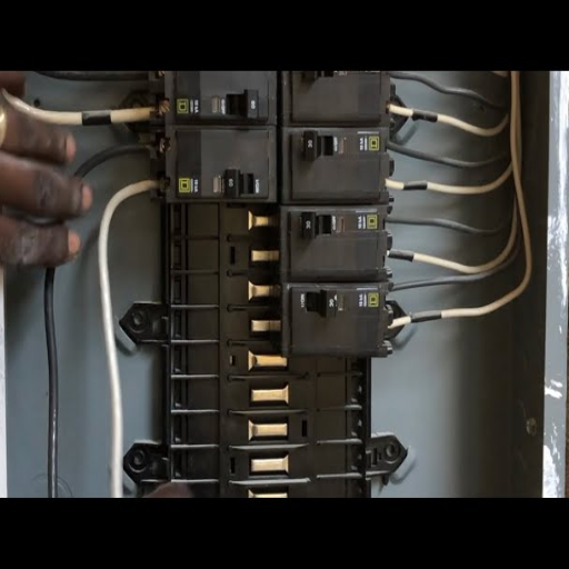
Quick Reference: When it comes to a circuit with a load of 60 amperes, the proper wire gauge would be 6 AWG for copper and 4 AWG for aluminum, based on a normal temperature rating of 75°C (167°F). This wire capacity will prevent heating and thus ensure safe current handling. It is always advisable to check wire specs and refer to local electrical code for compliance with area regulations as well as safety standards.
Understanding AWG Wire Sizes
The American Wire Gauge (AWG) system ranks as a consensus method of measurement, which is mainly followed to express the size or capacity of electrical wires. The wire becomes thicker as the AWG number decreases; this, in turn, makes it capable of handling a larger current with very little resistance or no overheating. A case in point is the copper wire of 6 AWG, which has a diameter of nearly 0.162 inches and a current-carrying capacity changing within 55 to 65 amps based on the type of insulation and the temperature rating. Heavy wires, for example, 4 AWG aluminum, despite having lower conductivity in comparison to copper, are lighter and cheaper in general for large installations. The correct wire choice is determined by the circuit’s amperage, voltage drop, distance, and environmental conditions. It is very necessary not only to abide by AWG sizing rules but also to conform to local electrical regulations in order to secure system reliability and safety.
Copper Wire vs. Aluminum Wire
While comparing copper wire and aluminum wire, their basic properties and potential applications should be the primary concern. Copper wire has an amazing conductance rate, meaning the electric current can easily pass through copper, and it would not generate much heat as compared to aluminum. Copper, too, is pretty much the same as steel in its strength and will even bear corrosion and oxidation without any protective coatings. Therefore, besides the actual electrical properties, copper is potentially the first choice for electrical circuits that require great performance, high quality, and reliability.
On the contrary, aluminum wire is much lighter and cheaper, which opens up the usage of aluminum in very large or very long installations. The only minus point regarding aluminum is that it has about 61% of the conductivity of copper, meaning a larger cross-section is needed to transmit the same current. Furthermore, aluminum wire expands and contracts more with temperature changes, which can cause the connections to break if proper handling and maintenance have not been performed.
Making the right decision between copper and aluminum depends on a number of factors, like the necessary amperage, the nature of the installation environment, and limitations of the budget. Copper is the most common past choice for applications with high durability and less maintenance demand; however, it is still quite expensive. Aluminum wire can be the solution in the case where the installation is dictated by weight and material costs, but it is necessary that the installation shows adherence to good practices and that all connections are well checked to avoid overheating or loosening.
| Property | Copper Wire | Aluminum Wire |
|---|---|---|
| Conductivity | Excellent (100%) | Good (61% of copper) |
| Weight | Heavier | Lighter |
| Cost | More Expensive | Less Expensive |
| Durability | High resistance to corrosion | Requires proper maintenance |
| Temperature Expansion | Minimal | Higher (can cause loose connections) |
| Best Use | High durability, less maintenance | Large/long installations, budget-conscious projects |
Recommended Wire Sizes for 60 Amp Circuits
Selecting the right wire size for a 60-amp circuit will require a comprehensive review of features such as wire material, type, and the length of the run to comply with safety standards and ensure the best performance. Generally, copper conductors will require a minimum of 6 AWG wire. To avoid the voltage drop, lengths at the far end might even require going up to 4 AWG. With aluminum conductors, on the other hand, a minimum of 4 AWG is suggested since aluminum has less conductivity than copper.
Wire type is a very important factor as well. Indoor and residential installations mostly use THHN or THWN-2 wires, which are highly durable and heat-resistant, as the usual wire type. However, in outdoor installations or those requiring cables that are buried, direct burial-rated or UF-B cables would likely be specified, thus being able to resist hazards inherent to the environment. It is always wise to check with the National Electrical Code (NEC) and local regulations to make sure you are complying, and also to use a licensed electrician for the installation so that all the connections are confirmed to meet the safety standards.
| Wire Material | Minimum Wire Size | Recommended for Long Runs | Common Wire Types |
|---|---|---|---|
| Copper | 6 AWG | 4 AWG | THHN, THWN-2 |
| Aluminum | 4 AWG | 2 AWG | THHN, THWN-2 |
| Outdoor/Buried (Copper) | 6 AWG | 4 AWG | UF-B, Direct Burial Rated |
| Outdoor/Buried (Aluminum) | 4 AWG | 2 AWG | UF-B, Direct Burial Rated |
Installing a 60 Amp Sub Panel
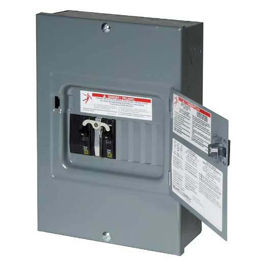
Materials Required
When planning to set up a 60 Amp subpanel, the following materials will be needed:
A subpanel rated at 60 A
A double-pole 60 A circuit breaker for the main panel
Wiring of proper gauge (usually 6-gauge copper or 4-gauge aluminum, depending on wire type and the length of the run)
Grounding wire and a grounding rod (if necessary)
The conduit and associated fittings for the installation (if covered wiring requires them)
UF-B cable or a similar wire for outdoor or underground use (if applicable)
Key Steps for Installation
- Power Off: The first step in every process is to turn off the power at the main breaker.
- Panel Mounting: Fix the panel in a suitable area which is Compliance with NEC regulations about clearance and access.
- Feeder Wires Install: Run the wire of the correct size feeder from the main panel to the sub panel. It should be ensured that a separate neutral and ground wire is used. If more than 100 feet of run, then consider the voltage drop, and the wire size should be adjusted according to that.
- Grounding System Connection: In case the subpanel is in a separate building, install a grounding rod and attach it to the subpanel’s ground bus. In the sub panel, separate neutral bus and ground bus are to be maintained.
- Main Panel Breaker Installation: The double-pole breaker rated at 60 A is to be placed in the main panel, and the hot feeder wires should be connected securely.
- System Testing: Once it is confirmed that all connections are tight and properly aligned, power is to be restored and testing done on the sub-panel circuits to ascertain their functionality.
Important Considerations
- Check for compliance with the NEC and local rules about wire size, grounding, and subpanel placement.
- Safety equipment, such as insulated tools and voltage testers, should always be used.
- If you are not familiar with electrical systems or code requirements, hiring a licensed electrician is highly recommended. If electrical work is not done correctly, it can pose dangers.
Step-by-Step Installation Guide
First, you need to position the sub-panel with respect to the main panel. Make sure that the location you have chosen for your installation is up to all the NEC and local building codes, especially regarding the area needed, proper airflow, and being able to reach it easily.
The subpanel that you will be purchasing should have an electrical load rating to be able to sustain your intended load. Check out the main panel’s compatibility and then the wire with the right gauge based on the amperage that is rated. Generally, 60-amp sub panels call for 6-gauge wire while 100-amp sub panels require 4-gauge wire. Make sure that your requirements are up to code specifications.
Cut off the main power panel before you start. This way, the system will be de-energized when you once the main breaker is turned off, and no electrical work will be affected. Make sure that the power is off by checking all circuits that go into the area where the subpanel will be installed with a non-contact voltage tester.
The next step is to run a power feeder from the main power source to the sub-panel. The cable can come in through a conduit or cable trays, as the NEC requires. Make sure that the cable is secure and there is enough slack for the proper connection at both panels.
The sub-panel must be fastened securely to an appropriate wall with the appropriate fasteners. It should be accessible and at a level position. The feeder wires connected to the lugs of the panel; these instructions are for the specific model of the panel from the manufacturer.
In the sub-panel, ground and neutral wires should be separated to avoid backfeeds. The NEC requires that the neutral bus not be grounded if it is in the sub-panel enclosure. Grounding has to be done through a separate ground bus bar.
On the bus bars of the sub-panel, place the circuit breakers for the individual circuits you intend to run. Ensure that the breaker is compatible with the sub-panel. Connect the circuit wires to the corresponding terminals and check that all the connections are tight.
Once all the connections are checked to be code-compliant and the sub-panel installation is marked finished, switch on the power at the main breaker again and then check the circuits of the sub-panel with a voltmeter or multimeter to test if they are working properly.
It is advisable to arrange for inspections done by the local authorities or by a licensed professional electrician to verify that the installation complies with safety and building codes. Fixes should be done before granting power to the subpanel. If the guidelines are closely followed and all authorities’ regulations are complied with, sub-panel installation could be done smoothly and safely.
Tools and Materials Needed
- Sub Panel Unit – It is essential to select a sub-panel that is specifically designed to fulfill the requirements of the amperage and circuits of your system.
- Circuit Breakers – Make sure that your sub-panel circuit breakers, as well as the main service panel breakers, will be compatible with each other.
- Electrical Conduit – The right size and type must be used, depending on local codes and installation conditions, such as PVC or metal conduit.
- Wire – Hot, neutral, and ground wires must be selected according to their ratings, based on the amperage and distance of the subpanel from the main panel.
- Grounding Rod and Wire – These are needed for proper grounding as required by local electrical codes.
- Screws and Anchors – They should be used for sub-panel and conduit installation by securing them to walls or structures.
- Voltage Tester or Multimeter – It is necessary for the purpose of checking connections and confirming the power outage.
- Electrical Box Knockout Punches – They are going to be needed for making the openings in the sub-panel’s wall to allow the passage of conduits.
- Fish Tape – This is for pulling wires through conduits or small spaces.
- Wire Strippers, Pliers, and Screwdrivers – These are the basic tools for preparing and connecting wires.
- Drill and Bits – They are for the mounting of the panel and also for making holes for the conduit.
- Electrical Tape and Wire Connectors – These are for the covering and insulating of the wire connections.
When you have all the materials and tools prepared in advance, you will be able to carry out the installation process without any hassles and in accordance with safety regulations. Always check the National Electrical Code (NEC) requirements and local regulations before starting the work.
Safety Precautions
Warning: It is critical to prioritize safety throughout the process of electrical equipment installation in order to prevent accidents, injuries, and damage to the equipment. Take these precautions seriously and follow them closely:
- Power Cut – Before proceeding with the installation, make it a point to turn off and lock up all the power sources that are to be affected using a lockout/tagout (LOTO) procedure, thus completely avoiding the possibility of electric shock.
- PPE (Personal Protective Equipment) – To protect yourself from the potential hazards to the maximum extent possible, wear the right protective clothes, such as insulated gloves, safety goggles, and non-conductive footwear.
- Check Tools and Equipment – Operate only the insulated and certified tools, inspecting them for damage or wear that could endanger safety.
- Grounding and Bonding – Make sure electrical connections are correctly grounded and bonded to avoid electrical faults and comply with NEC standards.
- No to Wet Environments – Working in wet areas is prohibited because moisture increases the risk of electric shock. Always keep the tools and equipment dry.
- Wiring Correctly – Check everything twice: wire connections, sizes, and insulation – it’s all about compliance with standards and preventing overloads or short circuits.
- Fire Prevention – Always have an electrically-rated fire extinguisher within reach. Never use water to put out an electrical fire.
Following these precautions will not only keep you in line with the safety standards but also greatly reduce the chances of accidents during the installation process. Always check for the latest NEC recommendations, and, if in doubt, consult with a licensed electrician for complicated installations.
Voltage Drop Considerations
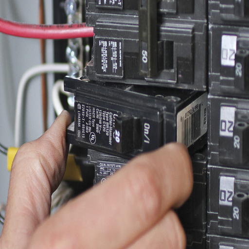
Voltage drop is the term that is used to denote the decrease in voltage when an electric current flows through a conductive material, which is attributed to resistance. If the voltage drop is too high, it may cause malfunctioning of the equipment, lower efficiency, or even destruction of the electrical parts. The following measures can be taken to reduce the voltage drop: Conductor Size – The use of correct-size conductors is essential. The larger conductors have lower resistance and are, therefore, necessary for long cable runs or high current circuits. Distance – The wiring distances should be kept to a minimum. The longer the distance, the more voltage drop will occur. Material – The use of conductors made of highly conductive materials, like copper, which is less efficient than aluminum for only a few applications, is recommended. Load – The circuit should not be loaded beyond its designed capacity, since the higher the current, the larger the voltage drop. For precise calculations, follow the National Electrical Code (NEC) regulations or apply voltage drop calculation formulas for making sure of compliance and performance of the system at the best level.
What is Voltage Drop?
Voltage drop is defined as the decrease in voltage across the circuit’s length caused by the resistance or capacitance of the conducting materials. The flow of electrical current through a conductor leads to some energy being dissipated as heat, which in turn lowers the voltage available at the circuit’s load end. The primary factors that affect voltage drop include the conductor’s length and diameter, its material (copper, aluminum, etc.), and the current flowing through it. High voltage drop can result in equipment malfunction, lower efficiency, and even damage to electrical systems. Therefore, to eliminate voltage drop, electrical engineers go for proper conductor sizing, circuit length minimization, and follow the standards as per NEC or IEC if applicable.
Calculating Voltage Drop for 150 Feet
In order to determine the voltage drop across a circuit with a length of 150 feet, one needs to take into account several aspects, such as the type of conductor, the size of the wire, the current load, and the voltage rating. The basic formula for voltage drop in a single-phase circuit is:
Voltage Drop (V) = (2 × Length × Current × Resistivity) ÷ Cross-sectional Area
Now, calculating for a circuit of 150 feet with copper conductors having a current of 20 amps at a voltage of 120 volts and using a conductor size of 10 AWG (which has a resistivity of about 1.21 ohms per 1,000 feet ), we will have the following calculation:
- The total circuit length (150 feet for each direction) should be converted to 300 feet.
- Now, multiply the length (300 feet) by the current (20 amps) to obtain 6,000.
- Then, this outcome is multiplied by the resistivity of copper (0.00121 ohms per foot for 10 AWG) to get 7.26.
- Next, divide by the cross-sectional area of 10 AWG wire (about 10.37 mm²), which is equivalent to converting from standard resistivity measurements.
This finally yields a volt drop value of around 3.5 volts or close to 2.92% of total voltage. Standards usually recommend keeping the voltage drop below 5% for best performance; thus, this figure is already acceptable. For longer distances or larger currents, it might be necessary to bump up the wire size to 8 AWG or greater in order to keep the voltage stable.
Always check with the relevant local electrical codes and regulations, which might impose extra conditions for conductor sizing and voltage drop tolerances to guarantee compliance and safety.
| Distance | Wire Size (Copper) | Current (Amps) | Voltage Drop (%) | Recommendation |
|---|---|---|---|---|
| Up to 50 feet | 6 AWG | 60 | < 2% | Acceptable |
| 50-100 feet | 6 AWG | 60 | 2-3% | Acceptable |
| 100-150 feet | 4 AWG | 60 | 3-4% | Recommended |
| Over 150 feet | 2 AWG or larger | 60 | < 5% | Required |
Impact on Wire Size Selection
The process of selecting wire size is a very important step during the design of the electrical system. The main factors that impact the right selection, which has to be a good combination of safety and efficiency, are the ampacity, voltage drop, conditions where the wire is going to be installed, and the type of metal used for the wire.
Ampacity Requirements
Ampacity is the maximum current that a wire can carry without getting too hot. It depends on several factors, including the diameter of the wire, the kind of insulation, and the surrounding temperature. For example, in a 30-amp circuit, a minimum wire size of 10 AWG copper is usually specified according to the standard electric codes, while larger current loads may need an 8 AWG or 6 AWG wire for safe operation. It is very important to match the wire size selected with the load requirements so that no overheating and fire hazards are created.
Voltage Drop Considerations
The voltage drop is a very important issue to deal with when they have to run long cables. For instance, if the total length of the circuit is 100 feet and 20 amps are flowing through it, the voltage drop for a 12 AWG conductor will be about 3.3%, which is below the maximum allowed limit of 5%. Another situation is if the length is increased to 200 feet, then, to limit the voltage drop, one may have to go for a 10 AWG wire size instead. The engineers usually make use of the voltage drop calculators or formulas to foresee and prevent this kind of loss occurring in the specified setup.
Material and Temperature
The type of wire used has a great impact on the performance of the circuit. When it comes to copper, which has a higher conductivity, it is generally preferred over aluminum for residential and commercial wiring. Temperature plays a very important role as well; conductors that are in hot areas might need to be de-rated, which will then result in choosing a larger wire size to keep the current flow (ampacity) stable. For example, a wire that is rated to work at 90°C in a conduit that has temperatures higher than 30°C might only need to carry a small current capacity.
Regulatory Compliance and Environmental Conditions
Following local electrical codes, for example, the NEC (National Electrical Code) in the USA, guarantees safety compliance. Besides that, environmental aspects like moisture or corrosive atmosphere should be considered, which might need special coatings, insulation types, or conduits to be used. In the case of outdoor and underground installations, UF (Underground Feeder) and THWN (Thermoplastic Heat and Water-resistant Nylon-coated) wires are the ones that give good performance in terms of durability.
Once all these factors have been taken into consideration, it becomes a very detailed and bespoke selection of the wire size that is based on the needs of the particular application, which in turn guarantees electric systems are both safe and efficient.
Common Questions About 60 Amp Circuits
If you are using a 60-amp circuit, it will be able to provide power for the basic electricals of a small house or a cabin. These basic needs can include lighting, small appliances, and limited heating or cooling. But a 60-amp circuit is definitely not enough for the modern and larger homes that rely on higher-powered devices like central air conditioning, electric stoves, or even several large appliances at the same time. To be on the safe side and to avoid any inconveniences, it is recommended that the standard homes should have a service of 100-200 amps of electrical power.
Usually, 6 AWG copper or 4 AWG aluminum is the wire size suitable for a 60-amp circuit. But based on the wire type and installation factors such as temperature, insulation type, and distance, the selection could change. The National Electrical Code (NEC) or a licensed electrician should always be consulted to validate the wire size for your particular case.
Yes, a 60-amp breaker can supply a subpanel, as long as the subpanel is rated for at least 60 amps or more. Moreover, the wire connecting the main panel and subpanel should be able to handle the amperage and ensure that proper grounding and bonding are in place for safety. Always follow the local codes and regulations.
The wiring of a 60-amp subpanel necessitates using a conductor that can withstand at least 60 amps. For households, this usually means the choice of 6-gauge copper wire or 4-gauge aluminum wire. Also, the wire must be appropriate for the surroundings; THHN or THWN-2 is usually good for indoor wiring, but for outdoor installation, UF-B wire or wire in a conduit is required. Apart from that, a 4-wire arrangement is a must, consisting of two hot wires, one neutral wire, and one separate ground wire. Be certain that the wiring complies with the National Electrical Code (NEC) as well as local rules. To accurately determine the wire type and size, take into account the voltage drop for long runs, and possibly, consult a licensed electrician.
Indeed, it is possible to use 4 AWG wire for a 60-amp circuit. The National Electrical Code (NEC) states that under normal conditions, 4 AWG copper wire has a maximum current rating of 70 amps, which is therefore appropriate for a 60-ampacity circuit. Nonetheless, ambient temperature, plus insulation type and installation conditions, among others, have to be considered in order to provide safety and compliance. Always check with your local electrical codes for specifics or ask a licensed electrician for advice.
For a 60 amp subpanel, you need a 60-amp double-pole breaker in the main panel. This breaker must be specifically rated for 60 amps and should be compatible with your main panel’s specifications. The National Electrical Code (NEC) states that under normal conditions, 4 AWG copper wire has a maximum current rating of 70 amps, which is therefore appropriate for a 60-ampacity circuit. Nonetheless, ambient temperature, plus insulation type and installation conditions, among others, have to be considered in order to provide safety and compliance. Always check with your local electrical codes for specifics or ask a licensed electrician for advice.
Summary and Key Takeaways
Essential Points to Remember
- Proper Wire Sizing is Critical: For a 60-amp circuit, use 6 AWG copper or 4 AWG aluminum wire as a minimum standard.
- Distance Matters: For runs over 100 feet, consider upgrading to a larger wire size (4 AWG copper or 2 AWG aluminum) to minimize voltage drop.
- Wire Type Selection: Use THHN or THWN-2 for indoor installations, and UF-B or conduit-protected wire for outdoor or underground applications.
- Safety First: Always turn off power at the main breaker before beginning any electrical work, and use proper personal protective equipment.
- Grounding Requirements: Maintain separate neutral and ground buses in the subpanel, and install a grounding rod if the subpanel is in a separate building.
- Code Compliance: Follow the National Electrical Code (NEC) and local regulations throughout the installation process.
- Voltage Drop Limits: Keep voltage drop below 5% for optimal performance. Calculate voltage drop for long wire runs and adjust wire size accordingly.
- Professional Consultation: When in doubt, always consult with or hire a licensed electrician to ensure safe and compliant installation.
- Inspection Required: Many jurisdictions require permits and inspections for subpanel installations—check your local requirements before beginning work.
Conclusion
Installing a 60-amp subpanel is a significant electrical project that requires careful planning, proper materials, and strict adherence to safety standards and electrical codes. The correct wire size is fundamental to the safety and efficiency of your electrical system, preventing hazards such as overheating, voltage drops, and potential fire risks. By understanding the differences between copper and aluminum wire, calculating voltage drop for your specific installation distance, and following the National Electrical Code guidelines, you can ensure a successful installation.
Remember that while 6 AWG copper or 4 AWG aluminum wire is the standard for most 60-amp circuits, your specific situation may require adjustments based on distance, environmental conditions, and local code requirements. The investment in proper wire sizing and professional installation will pay dividends in terms of safety, reliability, and peace of mind.
Final Safety Reminder: Electrical work can be dangerous and should only be performed by qualified individuals. If you lack experience with electrical systems or feel uncertain about any aspect of the installation, it is always best to hire a licensed electrician. The cost of professional installation is minimal compared to the potential risks of improper electrical work, which can include property damage, personal injury, or even loss of life. Never compromise on electrical safety—your family’s well-being depends on it.
Need Professional Help?
Always consult with licensed electricians for complex installations and inspections. They have the expertise, tools, and knowledge to ensure your electrical system is safe, efficient, and up to code.
Reference Sources
1. Study of Electrical Systems in the Engineering Faculty of Udayana University, Bukit Jimbaran
2. Microwave WPT Technology Developments for SSPS Application
3. Design and Evaluation of a Solar-Powered Groundwater Pumping System
Frequently Asked Questions (FAQs)
What size wire is required for a 60-amp sub-panel?
Usually, 6 AWG copper wire or 4 AWG aluminum wire is recommended for a 60-amp subpanel. The correct wire size must be chosen to maintain safety and efficiency in the system, especially in high-amperage applications.
How do I size the wire for a 60-amp circuit?
With respect to the 60-amp circuit wire size, distance plays an important role. In addition, one must take note of the wire types (copper or aluminum), distance from the set panel, and voltage drop that could occur. Of course, if the distance is less than 150 feet, one may use 6 AWG copper wire or 4 AWG aluminum wire.
Would 8 AWG copper wire be suitable for a 60-amp subpanel?
8 AWG copper wire is not recommended to be used for 60 60-amp subpanel. Any wire used must be able to handle the load safely. Use 6 AWG copper wire or 4 AWG aluminum wire for best results.
What are the requirements to install a 60-amp breaker in the main panel?
In installing this breaker, it is essential to ensure that the main panel can bear the extra load and that the wiring is adequately sized. This breaker should also fit the gauge wire with which it is being used-widely 6 AWG copper wire or 4 AWG aluminum wire.
Is a 60-amp service good for the detached garage?
A 60-amp service would, in general, serve the purpose for a detached garage, especially if it is to operate basic tools and lighting. Should there be plans to run heavy equipment or multiple high-demand devices at the same time, one ought to look into a 100-amp subpanel for more capacity.
What distinguishes a 60-amp subpanel from a 100-amp one?
The main difference between a 60-amp subpanel and a 100-amp subpanel is the capacity of secondary current. A 100-amp subpanel can take on a higher electrical load and is fit for larger homes or for higher power requirement applications. In contrast, the 60-amp subpanel is normally used for smaller jobs or homes.
How far can 60 60-amp service wire run without a voltage drop?
The maximum distance for any 60-amp service wire is entirely dependent on wire size and type. For example, with 6 AWG copper wire, you can run it about 150 feet. For any longer distance, increase the wire size to ensure efficiency.
What gauge wire should I use for 60 amps?
For 60-amp service, use 6 AWG copper wire or 4 AWG aluminum wire. This wire size will safely carry the amps without excessive heating and will promote efficient operation of the electrical system.
What is the purpose of equipment grounding in a 60-amp subpanel?
An equipment ground in a 60-amp subpanel acts as a safety feature, offering a route for electrical faults that could cause shock hazards or equipment damage. It is important that the ground wire is connected properly as prescribed by the NEC.