While discussing electrical circuits, the terms “series” and “parallel” often crop up-but what do they mean, and what differentiates them? Being familiar with these concepts is imperative, whether you are a first-year student or a DIYer who intends to further deepen the knowledge of electrical work on your own. In this article, we discuss major differences between series and parallel circuits, including their working, common applications, and importance. But, before the day finishes, you will have a clear idea of these basic principles and their practical assessment in real electrical systems.
Introduction to Circuits
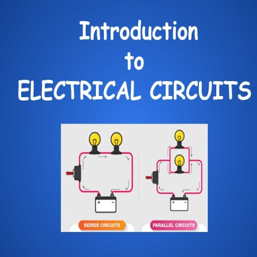
The term “circuit” refers to paths of electricity that allow a device to be operated. These consist of a power source, conductors, and a load (such as a lamp or motor). Circuits are classified into two main types: series and parallel. A series circuit consists of components arranged along one path so the same current flows through all components. However, a parallel circuit has more than one path for electric current to flow along, so elements can have current flowing along their respective branches independently. Knowledge of these is important to effectively design and troubleshoot an electrical system.
What are Series and Parallel Circuits?
There are two fundamental groupings of electrical circuits. In series circuits, the components come in the same order; current passes sequentially through every component in the series. Should something fail in one component, then the entire circuit connection is lost. These are often the more straightforward circuits to design, but less reliable if continuous running is an important factor.
On the contrary, parallel efforts open an organization that has numerous independent paths for current flow. Each branch works independently; in case one pathway is blocked, others will still get along. This makes parallel circuits very common in more complex systems, such as household wiring, to make sure power is delivered to many devices consistently. Both types of circuits are necessary in different applications depending on the requirement for reliability, complexity, and efficiency.
Importance of Understanding Circuit Types
It remains important to understand different types of circuits for anyone designing electrical systems in order to specialize in building systems that are efficient and safe for their purpose. Series circuits are simpler and somewhat applicable to string lights-the failure of one part ends up with the failure of the entire circuit. On the contrary, parallel circuits dominate current-day electrical work by making sure that each device functions independently. Understanding circuit types thus helps in troubleshooting problems, optimizing power consumption, and choosing appropriate components for different applications. Having mastered it forms an essential foundation in electrical engineering and in solving everyday electronic problems.
Applications in Everyday Life
Understanding electrical circuits is crucial as they power all sorts of appliances and gadgets, from home appliances to gadgets. Series circuit applications can be found in string lights because if one light bulb burns out, all the lights go out. On the other hand, parallel circuits are laid within homes for lights or devices so that no lights or devices work. The same parallel wiring systems are also highly used in automobile electrical systems to make sure that each unit, like headlights and instrument lights, functions reliably. Knowledge of circuits promotes wise energy use, increases safety, hope, and allows common electrical problems to be resolved. It is this understanding that helps to guide and maintain the technology on which we, in modern times, depend.
Series Circuit

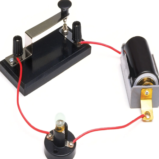
A circuit constituting the series type is an electrical circuit in which components are connected to one after the other on the same path. This implies that the current passing through any component is the same. Any interruption in one component in the circuit will result in interrupting the entire circuit. Series circuits find common application in string lights, where all components must be operative for the functioning to proceed.
Definition and Characteristics
A series circuit is any electrical circuit in which units of components are connected end to end in a single continuous path, so that a single current flows through each one in sequence. This is one of the properties of a series: the sum of the resistances of each element is the total resistance. For example, if a series circuit has three resistors of 5 ohms, 10 ohms, and 15 ohms, respectively, then the total resistance in the circuit is 30 ohms.
Other characteristics of series circuits are that the voltage across the circuit is equal to the sum of the voltage drops across the component(s). Ohm’s Law states that V (potential difference) equals I (current) times R (resistance). If the load of any load is off, then the whole road stops with a series circuit.
A few applications of series circuits occur in straightforward, stable electrical systems, such as an older string of Christmas lights, or in particular sorts of electrical testing devices. Understanding series circuits is very useful for an electrical engineer since it helps the engineer in designing and troubleshooting a variety of electronic systems.
How Current Flows in Series Circuits
Current flows through each component sequentially, traversing a single continuous path in a series circuit. Hence, the same current flows through every element in the circuit regardless of their resistances. This, however, is not true in the case of resistances, because the total resistance of the circuit is the sum of all the resistances of the elements in it:
Where R(total) stands for the total resistance, and R₁, R₂, and so on are for the resistances of the individual components.
Ohm’s Law, expressed as I = V/R, is essential in the explanation of current behavior in series circuits. Since the current (I) remains constant through the circuit, an increase in resistance (R) and a reduction in voltage (V) will decrease current proportionately.
I = 100V / 50Ω = 2A
The current here is common in the circuit and passes through each component. However, the voltage across each component develops depending on its resistance since voltage drops are proportional to resistance. For example, if one of the components is 20 ohms in the same circuit, then its voltage drop would be:
V = I * R = 2A * 20Ω = 40V
This means that the current is constant, but the voltage drop depends on individual resistances. Apart from this, since series circuits have the same current, they are sometimes employed in devices that require a steady current, such as sensors and certain LEDs.
An understanding of current behavior in series circuits immediately points to an obvious disadvantage: any break in the circuit interrupts current flow entirely and halts its operation; hence, the importance of maintenance and testing to ensure the integrity of the circuit in practical applications.
Voltage Distribution in Series Circuits
In a series circuit, voltage is shared among the components based on the resistances of the components. Ohm’s Law (V = IR) states that the voltage drop across each component in a series circuit is directly proportional to the resistance. Therefore, when the resistances are unequal, the component with the largest resistance will have a larger voltage drop.
- 2Ω Resistor: V = 1 A × 2Ω = 2V
- 4Ω Resistor: V = 1 A × 4Ω = 4V
- 6Ω Resistor: V = 1 A × 6Ω = 6V
This voltage distribution sums up to the total supplied voltage of 12V, which establishes that the sum of voltage drops across different elements in series is equal to the source voltage. This is an important characteristic in the design of electronic circuits for proper voltage allocation across components such as resistors, capacitors, and diodes.
A very important point in practical applications is that the resistances are not matched. An engineer selects resistors to provide voltages at levels delicate components can withstand so as not to harm them with stunning highs. Disorders in voltage distribution help in fault identification, as irregularities in the voltage drops can be symptomatic of a defective component or a bad connection.
Parallel Circuit
A parallel circuit is an electric circuit whose components are set up across the same two points so as to provide more current pathways. Such an arrangement assures the uninterrupted operation of other components if one fails because the current has alternative routes. The total resistance in a parallel circuit is always less than the resistance of any one of the branches, and the voltage is identical across each branch.
Definition and Characteristics
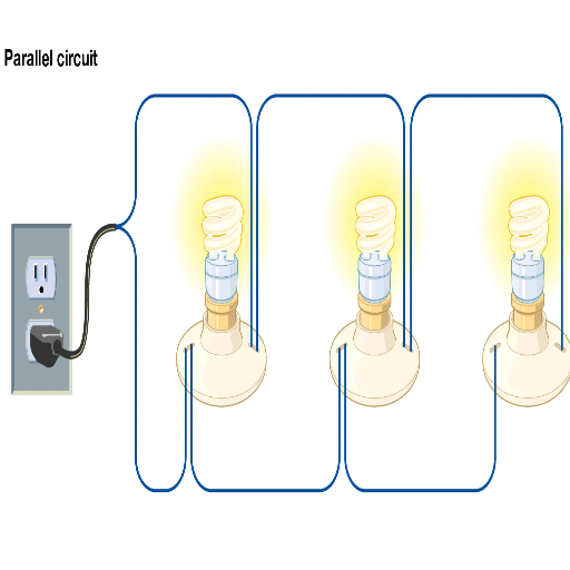
The circuit functioned in parallel as an electric configuration in which multiple passive components, like resistors or bulbs, are ergonomically connected with each other while being subjected to the same level of voltage from the source. All branches in a parallel circuit are operated independently; hence, current can flow simultaneously along two or more paths. Thus, if an individual branch fails, the remaining branches continue to operate. One calculates the resistance in a parallel circuit from the formula of reciprocals, which makes the resultant value less than the smallest value for any individual branch. Another very important feature of a parallel circuit is that the voltage drop across all the components is equal, whereas the current through each branch may differ. These characteristics make parallel circuits very suitable for applications like household wiring, where continuous operation of devices is required.
Current Distribution in Parallel Circuits
At whatever parallel circuit is set, the total current is established as the total current flowing through each branch consisting of. In an individual branch, current flows in accordance with Ohm’s Law, I = V/R. Since the voltage is equal across all the branches in a parallel circuit, the smaller the resistance of a branch, the greater will be the current through that branch.
The total current flowing through the source is effectively also obtained by adding the currents in all the branches. In mathematical terms, this is expressed as
This property assures an effective power allocation to each branch. Therefore, parallel circuits find frequent application where devices must operate independently, as opposition in one branch does not detract from the operation of others.
Voltage Across Parallel Resistors
Voltage across each of the resistors in a parallel circuit is the same and equal to that of the power source, because the resistors are directly connected to the very same two points of the circuit, and thus both points maintain an equal potential difference. Mathematically:
Accordingly, this property of parallel circuits assures that every branch has the same voltage, irrespective of the resistance values of the individual branches. Hence, the current in each resistor varies with its resistance as governed by Ohm’s Law: I = V/R. This property makes parallel circuits suitable for applications requiring a constant voltage supply to components, for instance, in house wiring systems, wherein each appliance works independently.
Difference Between Series and Parallel
The primary distinction between series and parallel circuits is established in how components are connected:
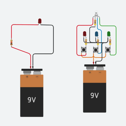
- Series Circuits: The components are connected end to end in a single path. The same current flows through all components, but the voltage is divided among them. If one component fails, the whole circuit stops working.
- Parallel Circuits: The components are across many paths. Each component gets the same voltage, but the current is divided depending on the resistance of each branch. If one component fails, the others can still operate independently.
This separation makes series circuits suitable for applications where components need to operate together, whilst parallel circuits are suitable for systems in which components need to operate independently.
Current and Voltage Differences
There lie some main differences when we compare current and voltage through series and parallel circuits. In the case of a series circuit, the current is similar throughout the components since there is just one defined path for the flow of electric charge. Voltage, on the other hand, gets divided across every component in the circuit; i.e., the sum of the individual voltage drops equals the source voltage.
Conversely, since all components in a parallel circuit are directly connected to the power supply, the voltage across every branch is equal to the source voltage. However, the current divides among the branches; the total current is the sum of the current through each branch. These basic distinctions between the two circuits affect the design and application of electrical systems, based on whether the system design favors constant current or voltage.
| Aspect | Series Circuit | Parallel Circuit |
|---|---|---|
| Current | Same throughout all components | Divides among branches; total current is sum of branch currents |
| Voltage | Divides among components; sum equals source voltage | Same across all branches; equals source voltage |
| Component Connection | End to end in a single path | Across multiple paths |
| Failure Impact | One component failure stops entire circuit | Other components continue operating if one fails |
Advantages and Disadvantages of Each Type
Series Circuit
Advantages
- Princeton would probably say it is simple in design and easy to set up because all components are connected in one path.
- It requires fewer materials-wiring, for example-so one can therefore think of the cost advantage.
- The current stays the same throughout the circuit, which is on the mark for applications that need constant current.
Disadvantages
- If one component fails, the circuit ceases to work.
- Voltage divides among components; thus, less voltage is available with each one.
- With more components, resistance increases, which could weaken performance.
Parallel Circuit
Advantages
- Each branch is supplied with full source voltage, and so the components are always ensured of working under optimal conditions.
- If one branch goes bad, the other branches procrastinate.
- Adding components will not increase the total resistance too much because the current is complicated among the branches.
Disadvantages
- The greater the design stages that will be required together with wiring, the cost of assembly will at least increase.
- The total current increases as more branches are added; hence, the source of power can become strained.
- An abortive situation may arise in current distribution if the branches have differing resistances.
Real-world Examples of Series vs Parallel Usage
That is to say: we employ series and parallel circuits in our day-to-day applications- each one is chosen based on particular advantages.
Series Circuits
These have come to be seen in places or in instruments where simplicity and a standard current are needed. Take the case of string lights; it is probably the most evident example. In faded designs, lights are interconnected in series, meaning that if one bulb burns out, the entire string goes dark because of the circuit breaker. Another example would be some types of battery packs. Here, the batteries are connected in series so that the voltage being supplied is increased.
Parallel Circuits
In use, these find their way into household electrical systems, where it becomes imperative for people to have devices operate independently. Parallel wiring is used in home outlets and lighting circuits so that shutting off one appliance does not affect others. Another example is car electrical systems, in which the headlights and other components are wired in parallel to maintain a constant performance irrespective of load variations.
Both configurations are an integral part of electrical and electronic designs, thematic basis on reliability, performance, and cost parameters.
Applications of Series and Parallel Circuits
Series and parallel circuits are often combined to meet specific design criteria.
Series Circuits are used in applications where a constant current supply is required. String of lights or battery packs belong in this category, basically anything that requires a constant current flow through the circuit. If a component fails, the whole circuit stops working, which can be an advantage of safety in certain types of systems.
Parallel Circuits have applications where the components require a constant voltage across them. This includes residential wiring and automobile systems. The components may run by themselves in parallel, thus ensuring the reliability of the site on the failure of another component.
Each configuration is selected depending upon the requirements that are application-centered within the system, weighing performance, reliability, and cost against each other.
Simple Circuit Configurations
When discussing simple circuits, two primary types series and parallel-must be considered. A series circuit joins components along a single path, forcing the current to be the same through all of the elements. This type of circuit finds applications when a constant flow of electricity is required. But then again, the disadvantage comes in that if any one component ceases to work, the whole circuit ceases to work. On the other hand, a parallel circuit has all components placed across two or more paths, which will contribute to giving the current different paths; hence, in case of failure of one component, others will continue to work with full efficiency. These circuits are very much used in electrical work in homes for their reliability and even distribution of voltage.
Use of Series and Parallel in Electronics
Both the series and parallel circuits are of use in different applications in electronics, depending on the need. In my view, series circuits are used when the same current must flow through several components; an excellent example would be in string lights. The parallel circuit is most suited where reliability is a factor, say in house wiring, where you want components working independently if one fails. Both so created configurations have vital roles, and I would use one or the other depending upon the requirements of the project.
Short Circuits: Causes and Prevention
Imagine a situation where electricity flows along an unintended path that offers low resistance; this is what is called a short circuit. This generally occurs due to exposed wires, loose connections, or faulty appliances with damaged insulation that permits the free flow of current, leading to overheating or worse, fires.
An analysis of short circuits leads to the determination of actions keeping short circuits at bay. Such actions include inspecting wiring and equipment regularly, making sure good insulation is present, and quickly replacing any wire that is damaged or frayed. In the event of a short circuit, the installation of a set of circuit breakers and a fuse interrupts the flow of current and causes no damage or hazards. Keeping the electrical system dry and ensuring not to overload any outlet are some additional preventive measures one must take. A firm grasp of these causes and their prevention can go a long way toward improving electrical safety.
Reference Sources
Comparison of the Performance of Mini Generator Water Turbines in Series and Parallel Flow Systems
Regenerative Braking System for Series Hybrid Electric City Bus
Frequently Asked Questions (FAQs)
What is the difference between series and parallel circuits?
Series and parallel circuits in physics refer to two distinct types of arrangements of electrical components within a circuit. Series circuits are formed when components lie within the same path-the current flows through each component consecutively. In parallel circuits, components are connected in parallel such that there exist many paths for the flow of electric current. Therefore, should a component fail within a parallel circuit, the other components will continue to operate.
What is the effect of resistors in series on total resistance?
Based on the configuration of resistors in series, the total resistance is equal to the summation of the resistance values for each resistor in the series. In other words, if there are two resistors in series, the total value of their resistance can simply be calculated by summing up the resistance of those two resistors. The series resistance means an increase in the total resistance, thereby limiting any larger current from freely passing through the circuit.
Can capacitors be connected in series?
Yes, so capacitors can indeed be placed in series. When capacitors are connected in series, the capacitance of the circuit is less than the capacitance of the smallest capacitor in the series. The total capacitance for a series circuit is calculated by taking the sum of the reciprocals of the capacitances of the capacitors and then taking the reciprocal of that sum. This arrangement is adopted equally whenever a greater voltage rating is required.
What are the advantages of using parallel resistors?
Parallel resistors offer several advantages. One is the reduction of total resistance, and therefore, a greater current can flow through the circuit. Each resistor experiences the same voltage on its terminals, improving performance and efficiency. Another advantage is that if one resistor should fail in a parallel network, the others remain in operation; this often makes parallel resistor networks preferable from a reliability standpoint.
How does a voltage divider work in a series circuit?
When two resistors are arranged in series, they set up the voltage divider circuit, which divides the total voltage furnished by the voltage source. The division of voltage occurs according to the resistance values; thus, the output voltage, determined by these values, can be utilized for any other circuit component. This, of course, comes into play when something else needs a lower voltage than that provided to it by the battery or the voltage source.
What happens when there is a break in a circuit?
The break in the circuit interrupts the flow of electrons; hence, all components cease to be active. In a series circuit, if one element ceases to work (a resistor or a bulb, for example), the circuit opens now, and current cannot flow. But when in parallel, pathways for current flow are still present in spite of one path being broken, and hence, the rest of the components remain functional.
How do batteries connected in series compare to those that are connected in parallel?
Batteries connected in series thus augment the voltage: the voltages of each of the batteries become added together. Meaning, two 1.5V batteries in series present a voltage of 3V across them. In contrast, batteries connected in parallel would remain at a voltage equal to that of a single battery; however, they would increase the total current capacity and thus garner longer operating time without increasing voltage. This crucial distinction should be kept in mind when making circuits for specific voltage or current requirements.
What is the significance of voltage and current in series and parallel setups?
For series configurations, the current is the same throughout all components, whereas the voltage divides amongst them. In cases of parallel configuration, every component gets the same voltage, but what current that passes through different resistances in each path may vary. It is essential to understand the relationship between voltage and current to design an efficient circuit since each component’s performance and the entire circuit functionality depend on them.
What are the features of parallel capacitors?
Generally considered parallel capacitors combine capacitance values. In other words, when capacitors are connected in parallel, their total capacitance is simply the sum of all individual capacitances. This serves to increase the charge storage capability and provide a higher total capacitance feature that is useful in filtering and energy storage operations in electrical circuits.