The proper wiring of a VFD’s furnace is of paramount consideration for those dealing with heavy machines and automated systems. The VFD is at the nexus of motor speed and efficiency control, so correct wiring and configuration are essential for achieving quality performance, ensuring safety, and other key factors. This post provides an overview of the basics of VFD drive wiring, covering wire connections, control systems, and key considerations for a seamless installation. Thus, whether one is an experienced technician or just learning to gain new skills, all practical hints and step-by-step instructions provided herein will help cement the fundamentals of VFD wiring.
Introduction to VFDs and Wiring
The VFDs serve the purpose of varying the speed-torque relationship of an electric motor in response to changes in the power frequency and voltage applied to it. The best wiring is crucial for a VFD to operate, as it ensures efficiency, safety, and reliability. VFD wiring should see wiring from the source to the driver, wiring from driver to motor, and wiring a control signal according to system configuration. One should always use wiring diagrams and guidelines provided by the manufacturer, as well as the wire types recommended by the manufacturer, and follow proper grounding techniques to avoid electrical problems. Ensuring that all potential errors during installation have been minimized will guarantee the correct operation of the VFD system if the above are followed.
What is a Variable Frequency Drive (VFD)?
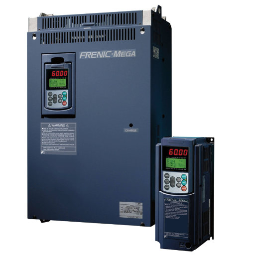
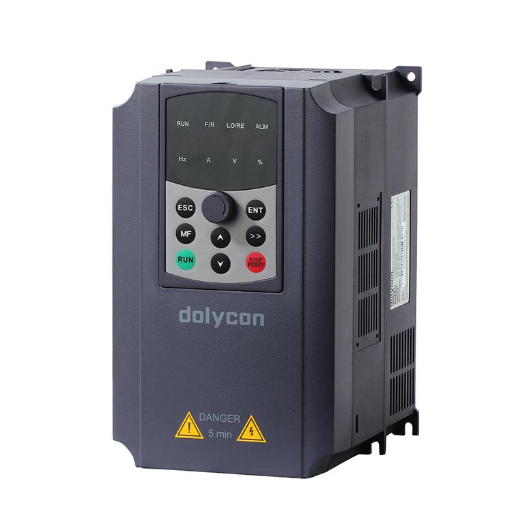
An electronic device, called VFD, controls the speed and torque of an electric motor by varying the frequency and voltage supplied. In industrial and commercial fields, VFDs are recognized as key elements that optimize motor performance and enhance energy efficiency. Industrial VFDs permit smooth acceleration and deceleration, allowing precise motor control while reducing mechanical stress on the machines and thus significantly improving the life of the equipment.
Modern VFDs offer a range of advanced features, including diagnostics, overcurrent protection, and energy-saving modes. According to current records, industries that use VFDs save approximately 30-50% of energy compared to traditional fixed-speed systems. VFDs, therefore, assist with automation tasks and offer flexibility in varying motor speeds with changing load requirements, making them crucial in industries such as manufacturing, HVAC plants, and water treatment.
VFDs, therefore, perform the essential function of making plant processes more energy-efficient and reliable, while simultaneously reducing operating costs and environmental impacts, thereby aligning them with global sustainability goals.
Importance of Proper Wiring in VFD Systems
A proper wiring methodology in VFD systems is crucial for ensuring safe, reliable, and efficient operation. Improper wiring can, for instance, cause motor failure, electrical noise interference, or the absolute destruction of the VFD unit. Another significant consideration is to provide proper grounding; the Earth’s grounding of the VFD can create electromagnetic interference (EMI), which interferes with the operation of sensitive equipment and violates compatibility standards, such as IEC 61800-3.
In cable selection, everything matters. For shielded cables, the purpose of shielding is to reduce high-frequency emissions and comply with electromagnetic compatibility (EMC) regulations, which prevent stray currents from causing disturbances. Another consideration is having the appropriate conductor sizing to prevent current overloads or voltage drops, which can lead to decreased motor efficiency and lifespan. Industry research suggests that undersized conductors could even cause a 2% efficiency loss at full load in VFD systems due to overheating.
Another factor that adds to the practical difficulties includes the actual installation of the cabling, with ‘ good installation practice ‘, keeping separation among power, control, and signal cables for the reduction of crosstalk and signal noise, as these are prevalent issues within VFD installations. Proper wiring, following standards such as the NEC (National Electrical Code) or IEC, ensures that the wiring configuration aligns with safety and performance expectations.
Proper wiring extends not only to VFDs and equipment but also to cost reduction through reduced downtime and lower maintenance costs. A better guide in achieving this would be to witness the accuracy and proper installation of electrical standards. With that investment, the overall system’s reliability can be improved, along with achieving the highest level of energy efficiency.
Basic Components of VFD Wiring
There are several components to be considered for the VFD wiring diagram since all of them contribute to its functionality and reliability:
Power Supply Connections: A Variable Frequency Drive requires a stable and appropriately rated power supply to function effectively. The supply is three-phase, primarily AC voltage, which the drive then manipulates to different frequencies and voltages at the output. Typically, the voltage ratings used in variable frequency drives are 230V, 460V, and 575V, as specified by the motor requirements and respective applications.
Control Terminals: The VFD control terminals need to interface with other external devices such as sensors, switches, or a PLC. It takes start/stop commands, speed feedback, and control signals. For instance, speed controls are typically handled via analog signals (0 to 10 volts or 4 to 20 milliamperes), whereas digital inputs address on/off states and fault resets.
Motor Connections: The output terminals of a VFD connect to the input terminals of the motor. Must use appropriately sized cables, insulated for high-frequency and voltage variations created by the drive. Cables with shielding are often considered better for preventing electromagnetic interference (EMI) with devices nearby.
Grounding and Shielding: Grounding is an essential aspect in VFD wiring. An efficient grounding system reduces electrical noise and increases operator safety. Regarding shielded cables, their shields should be grounded at both the drive and motor ends to achieve further EMI reduction. Uniform application of grounding practices would meet safety regulations and enhance the system’s performance.
Protective Devices: Protective devices, such as circuit breakers, fuse blocks, and surge suppressors, form part of the system to guard against short circuits, overvoltages, and system faults. Using circuit breakers that are rated correctly, the system operates within their specified electrical limits and thereby offers a reasonable degree of protection to the drive and downstream equipment.
Communication Interfaces: Modern VFDs are typically equipped with communication protocols that integrate Modbus, Ethernet/IP, or PROFIBUS into IC automation processes, enabling online monitoring, diagnostics, and controls to enhance performance and efficiency.
Cooling Systems: VFDs typically incorporate forced air cooling, which is achieved through the use of fans or other external cooling methods. Keeping the equipment cool is of utmost importance during installation to prevent affecting the operating temperature.
Although understanding and applying these simple components during VFD installation results in better operational efficiencies, improved motor controls, and a longer life of the equipment, it is nevertheless advisable to follow VFD technology trends that reflect the introduction of features for further ease of integration and operation.
Wiring Configurations for VFDs
When installing a Variable Frequency Drive, good wiring configuration is critical to achieving safe and efficient operation. Key considerations will primarily include power supply connections, motor connections, and control wiring.
Power Supply Connection: Connect the incoming power supply to the input terminals of the VFD, ensuring the voltage and phase match those of the VFD. Protection must be provided, either through a circuit breaker or a fuse.
Motor Connection: Connect the motor to the VFD’s output, ensuring the phase sequence is correct and the connections are secure. Verify that the motor’s ratings match those of the VFD to prevent any operational issues.
Control Wiring: Proceed with wiring the control terminals for the desired operation, including start/stop commands, speed references, or feedback signals. Use shielded cables to resist signal degradation caused by electrical noise.
Achieving optimal VFD operation highly depends on the clarity of the wiring diagrams and strict adherence to the manufacturer’s instructions.
Single-phase vs Three-phase Wiring
Single-phase VFD wiring involves a Line (L) and a Neutral (N), while three-phase VFD wiring includes three Lines (R, S, T) and a Ground (E).
|
Parameter |
Single-phase |
Three-phase |
|---|---|---|
|
Input |
L, N, E |
R, S, T, E |
|
Power |
230V |
230V/400V |
|
Output |
U, V, W |
U, V, W |
|
Uses |
Low power loads |
High power loads |
|
Cost |
Lower |
Higher |
|
Efficiency |
Moderate |
High |
Choosing the Right VFD Cable
Selecting the right VFD cable is crucial for ensuring optimal system performance and longevity. Consider shielding, insulation, temperature rating, and voltage rating. Shielding protects the cable from electromagnetic interference (EMI), which can induce unwanted noise into sensitive equipment. Cables should be selected based on having rigid insulation that withstands the heat generated by the VFD during operation, along with an appropriate temperature and voltage rating, particularly suited to your application.
Cable selection, in turn, should consider cables designed for use with VFDs, as these exhibit low coupling capacitance that would otherwise reflect gratuitous waves. For instances where a long cable run is required, select cables with low impedance mismatch to minimize overvoltage stresses at the motor terminals. Safe and reliable systems are all at stake when you carefully match your cable specifications to the needs of your system.
Control Systems and VFD Performance
Control systems can significantly influence and optimize VFDs by regulating motor speed, torque, and direction with extreme precision. Integrated feedback mechanisms enable control systems to ensure that VFDs operate with maximum efficiency in terms of energy consumption, matching energy demand with varying load characteristics. Proper coordination between the control system and VFD ensures efficiency, reliability, and cost savings, including a longer lead time for the motor. Pertinent communication protocols, coupled with continuous monitoring systems, would help maintain the motor’s performance consistency and identify early signs of trouble.
Understanding VFD Control Methods
Variable Frequency Drives (VFDs) employ three principal methods of motor speed and torque control, each suited for a specific type of application. Control methods include Volts per Hertz (V/f) Control) Sensorless Vector Control (SVC) and Closed-Loop Vector Control.
Volts per Hertz (V/f) Control: V/f control is the simplest and most commonly used control in VFDs. It maintains a constant ratio between the voltage and frequency to ensure the motor operates smoothly. This control method is applicable where high precision is not required, such as in conveyor systems and fans. Characteristic advantages of V/f control include low implementation costs and ease of construction. However, this does not give a good dynamic response and accurate torque control when compared to vector methods.
Sensorless Vector Control (SVC): This method provides excellent torque and speed control without the use of feedback devices, such as encoders. It gives higher accuracy and response than the V/f method by computing motor parameters in real-time. Therefore, SVC can be used for pumps, compressors, and simple motion control systems. Research has shown that SVC can provide torque accuracy of 90%, which is a good compromise between V/f control and the more complex closed-loop control.
Closed-Loop Vector Control: Closed-Loop Vector Control is the most complex and accurate method. It achieves torque and speed regulation by employing feedback devices such as encoders or resolvers that continuously measure the motor’s actual performance. This ensures optimal performance under varying load conditions and is suitable for precision applications, such as robotics, elevators, and CNC machines. Data indicates that closed-loop control can achieve torque control accuracy above 95% while massively improving system stability.
Each method presents certain advantages and disadvantages, making the choice of method conditional on the specific application. In light of the control methods and their corresponding operation profiles, considerable energy savings, process efficiency, and reliability can be attained by any business.
Factors Affecting VFD Performance
Numerous factors influence the operations of Variable Frequency Drives (VFDs), and assessing these can be beneficial in achieving optimum VFD operation:
Environmental Conditions: Ambient temperature and humidity, as well as the presence of dust or corrosive gases, may be detrimental to a VFD’s performance. If the drive becomes overheated or is exposed to harsh environments, it may lead to premature failure or derating of the drive.
Load Characteristics: The load connected to the VFD can be of constant torque, variable torque, or intermittent type. This affects the efficiency and operational stability of the VFD. To optimize the performance, it is therefore essential to match the drive to the load type.
Power Supply Quality: Voltage variations, power surges, and harmonics in the power supply can adversely affect the operation of the VFD. If properly selected and installed, surge protectors and harmonic filters would ensure stable operation and protect the drive.
Motor-VFD Compatibility: Proper care must be taken to ensure the motor’s compatibility with the VFD, considering factors such as motor capacity, insulation, and control method, to avoid potential inefficiencies or damage during operation.
Parameter Settings: Properly setting the VFD’s parameters, including acceleration/deceleration time, overload setting, speed range, and other relevant settings, will enable smooth and energy-efficient operation while avoiding undue strain on the motor.
If one focuses on these factors, it would help maximize the operational life, reliability, and efficiency of VFD systems, thereby bringing their merits to the forefront for various industrial and commercial applications.
Safety Protocols in VFD Wiring
VFD wiring requires safety calculations to ensure smooth and safe operations. The following are a few key precautions to be aware of.
Follow Manufacturer Guidelines: Always consult and comply with the VFD manufacturer’s documentation and wiring guidelines to ensure compatibility and reduce the risk of damage and malfunction.
Grounding and Bonding: It places great importance on adequate grounding to minimize electrical noise and minimize the danger of electric shock. The VFD and the motor must be correctly grounded according to local electrical codes and standards.
Use Shielded Cables: Shielded cables should be used for power and control wiring to avoid EMI. The shields should be securely connected to the ground at one end only to prevent ground loops.
Isolate Power Sources: Circuit breakers and fuses shall be installed in both the power source and the VFD to provide overcurrent and short-circuit protection. Disconnect switches shall be installed for servicing.
Control Wiring Separation: Control wiring must be kept separate from heavy power cables to prevent crosstalk and interference with sensitive signals.
Temperature and Environment: The VFD shall be installed in a well-ventilated and dust-free environment that maintains temperature limits as defined in specifications.
Testing and Verification: Insulation resistance testing shall be carried out, all connections confirmed, and parameter settings double-checked before energizing the system to verify safe operation.
Likewise, by following these protocols, common risks associated with electric shock, overheating, and premature VFD failures can be effectively mitigated, allowing for a safe and efficient system to be maintained.
Troubleshooting and Preventing Failures
When trying to diagnose the causes of a VFD failure, always begin by checking any error codes displayed on the VFD panel, as they usually provide hints as to what is causing the problem. Next, ensure that the input power supply being fed into the input terminals remains stable and within the specified voltage. Check all wiring to ensure none appears damaged or is not adequately secured. In the case of a motor being problematic, check for any overheating and abnormal noise that could indicate mechanical or alignment issues.
Cleaning and dusting periodically are vital steps for maintaining VFD working conditions, as dust accumulation can compromise the cooling system. Replacement of worn-out parts, including cooling fans and capacitors, must follow inspections. Ensuring that the cooling system surrounding the VFD meets the manufacturer’s standards and that the installation complies with environmental regulations is the ultimate goal. Strict compliance with such precautionary measures will reduce downtimes and enhance equipment life cycles.
Common Causes of VFD Wiring Failures
VFD wiring failures can occur for various reasons, often due to installation errors, environmental factors, or simple wear and tear over time, with these factors being the primary culprits. Loose or poorly terminated connections are relatively common and can cause flashing, voltage imbalances, or even a total system shutdown. Other common problems include using cables that do not suit the VFD’s operating conditions, like cables with inadequate shielding or insulation against EMI and high-frequency noise. Exposure to hostile environmental conditions, such as high temperatures, moisture, or contaminants, can also degrade wiring and lead to actual failure. Implementing high-quality installation checks, scheduling periodic inspections, and utilizing VFD-rated cables will significantly mitigate these risks.
Diagnostic Techniques for VFD Systems
Servicing VFDs involves a systematic approach that requires identifying and rectifying potential faults. Begin by inspecting VFD items and components, including cables, connections, motor terminals, and similar elements, for signs of wear, tear, or damage. Using a multimeter or oscilloscope, measure the input and output voltage, current, and waveform quality, as these elements can highlight abnormalities such as voltage imbalances, harmonic distortions, or output frequencies that do not match expectations.
Error codes, alarm histories, and internal diagnostics tracking are the main VFD diagnostic features. Whether the error conditions included overvoltage, undervoltage, overtemperature, or ground faults, the error codes provide an immediate clue. Occasionally, check that the cables are properly grounded and shielded from EMI interference, which could otherwise cause erratic behavior.
Using a thermal imaging camera can further reveal hotspots generated by bad contacts or overloaded conditions. These days, software-based monitoring solutions also provide real-time analytics on VFD performance, trends, and usage patterns, facilitating preventive maintenance. These techniques, when combined, make the VFD system entirely trustworthy and sustainable in the long term.
Best Practices for Maintaining VFD Wiring
VFD-maintenance wiring should follow best practice guidelines to assure maximum system effectiveness and prevent costly downtime. The first guideline recommends using shielded cables designed for VFD applications to reduce EMI. These cable shields must be grounded at both ends to achieve efficient EMI barrier properties. The second guideline suggests respecting the cable lengths as recommended by the manufacturers. This avoids any excessive voltage drop or reflected wave occurrences. If the cable runs become very long, output reactors or terminators may be required.
Regular checks must be conducted to spot possible signs of wear, loose connections, and insulation damage. Such faults always lead to overheating or failure. After that, torque-terminal connections are used at the values specified by the manufacturers to ensure excellent electrical contact and prevent loosening due to vibration. Power wiring must be separated from control wiring to minimize crosstalk and interference risks- run each type of wiring in separate conduits or keep them spaced apart.
Lastly, prevent dust or moisture from contaminating and decorating the working environment of VFD components. Dust and water can degrade insulation, potentially leading to short circuits. Such arrangements would help VFDs run optimally, keep them well-maintained, guarantee fewer downtime instances, and consequently give the most excellent longevity to VFD systems.
Learning More About VFD Drives
To learn about VFDs, start by studying their basic function of controlling the speed and torque of any given electric motor by adjusting the frequency and voltage at the motor inputs. Used in industries for energy efficiency, increased equipment lifespan, and precise motor control, VFDs find wide application. A comprehensive understanding can be obtained from manufacturer guides, industry white papers, and training courses conducted by recognized bodies such as IEEE and NEMA. Additionally, refer to product manuals and online references provided by VFD manufacturers, which often contain detailed specifications, troubleshooting methods, and best practice techniques for installation and maintenance. Ensure that you focus on credible sources tailored to your specific motor and its application needs.
Industry Standards and Guidelines
When dealing with VFD systems, adherence to these prevailing codes and standards is mandatory for ensuring safety, reliability, and efficient operation. Standards issued by organizations such as the Institute of Electrical and Electronics Engineers (IEEE), the National Electrical Manufacturers Association (NEMA), and the International Electrotechnical Commission (IEC) are usually accepted in the industry. For instance, IEEE 519 addresses the control of harmonics within electrical systems and ensures that VFDs do not cause increased distortion of power quality. NEMA standards-i.e., NEMA MG1-ensure that the motors that are coupled with VFDs meet specific performance criteria and can function through specified periods.
Current information indicates that these standards, when adhered to, can result in a 30% reduction in energy consumption in industrial applications utilizing VFDs. Also defined in the IEC 61800 series are the functional specifications and testing methods for motor control systems, making it one of the foremost references for system integrators and engineers. An annual review of any alterations to such standards will warrant alignment with methodological procedures and technical updates to the latest versions. Applying these codes and standards during design, installation, and maintenance can lead to performance optimization with reduced risk and operational inefficiencies.
Future Trends in VFD Technology
One major trend I see in VFD technology is the increased integration of IoT and innovative capabilities. They can now help monitor in real-time, predict maintenance, and enhance energy efficiency, among other benefits. Additionally, considerable effort is being invested in making VFDs compatible with renewable energy systems, in recognition of the global shift toward sustainable solutions. I also believe that significant strides will be made in terms of miniaturization and cost reduction, enabling these systems to penetrate deeper into the markets of various industries.
Reference Sources
1. Automation of Industrial Machinery
2. Characteristics of Adjustable High-Phase Order Induction Motors and Their Optimal Design
3. Analysis of 12-Level Cycloconverter to Minimize THD in 3-Phase Induction Motors
Frequently Asked Questions (FAQs)
What is a VFD Drive Wiring System?
A VFD drive wiring system is an arrangement of electrical connections that allows for the control of a variable frequency drive (VFD). This system regulates motor speed and torque by varying the frequency and voltage supplied to the motor, thus enhancing performance and efficiency.
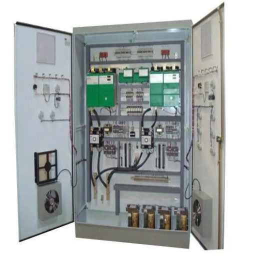
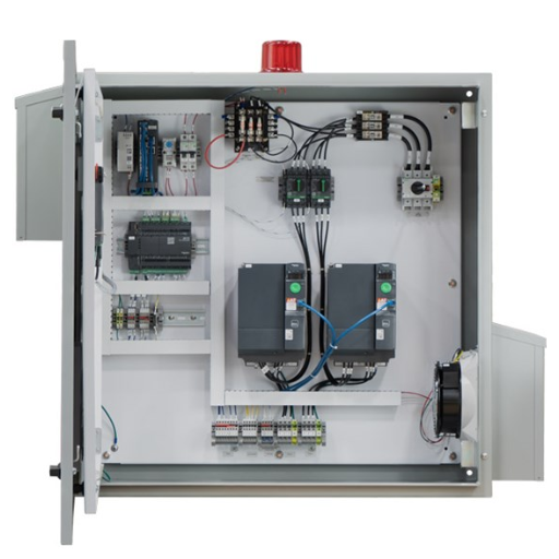
How is VFD Wiring Related to Control Panels?
VFD wiring is closely associated with control panels as they house the controls that manage the VFD operation. The control panel interfaces with the VFD, allowing users to set parameters and monitor performance, ensuring optimal motor operation.
What Are the Safety Considerations in VFD Wiring?
When working with VFD wiring, safety is paramount. It’s essential to ensure that all connections are properly insulated and that the system is grounded to prevent electrical shock or equipment failure. Additionally, following manufacturer guidelines and local codes can help mitigate risks.
What Causes VFD Wiring Failure?
VFD wiring failure can be attributed to several factors, including improper installation, exposure to environmental conditions, and wear and tear over time. Regular inspections and maintenance can help identify and address these issues before they lead to significant failures.
How Can VFD Cables Save Energy?
VFD cables are designed to minimize energy loss during transmission, which helps in saving energy. By using high-quality wires that meet the specific requirements of a VFD, you can enhance system efficiency and lower operational costs.
What is the Difference Between Single and 3-Phase VFD Wiring?
Single-phase VFD wiring is typically used for smaller motors, while 3-phase VFD wiring is utilized for larger, industrial motors. The 3-phase systems provide better performance and efficiency due to smoother power delivery and reduced vibration.
How Do VFDS Enhance Motor Performance?
VFDS are used to enhance motor performance by allowing precise speed control and torque management. This capability not only improves the motor’s efficiency but also extends its lifespan and reduces energy consumption.
How to Learn Proper VFD Drive Wiring Techniques?
Learning proper VFD drive wiring techniques involves studying electrical principles and best practices. Hands-on training, manufacturer resources, and industry certifications can provide valuable knowledge and skills necessary for effective VFD installations.