Proper ground rod spacing has always been a critical aspect of any grounding system, but is often either misunderstood or overlooked during installation and design. All types of projects, whether residential, commercial, or industrial, require knowledge of ground rod placement principles to make electricity safer, more reliable, and efficient. This article examines the key aspects of ground rod spacing, providing practical guidance on implementing them, along with expert recommendations for designing grounding systems that meet both regulatory requirements and real-world needs. There will be information on the science of good spacing, as well as some nightmares and their solutions, which you must be aware of so that your system can perform effectively to protect you.
Understanding Ground Rods
Ground rods serve as some of the most critical components in electrical grounding systems, as they afford an adequate or excess amount of electricity, lightning, or fault currents into the earth. This offers safety to the electrical system against the harmful shocks inherent in it, or minimizes equipment damage. Typically, ground rods are made of conductive materials, such as copper or galvanized steel, which provide a low-resistance path for dissipating electrical current. Proper installation, in terms of both depth and spacing of ground rods, ensures optimal performance and compliance with the requirements issued by regulatory agencies.
What is a Ground Rod?
A ground rod is a crucial component of the grounding system, designed to protect buildings and people from electrical surges and faults. Usually, they are made of highly conductive materials, such as copper or galvanized steel, and are driven deep into the earth to create a direct, low-resistance conductive pathway. This path allows excess electricity from sources such as lightning strikes, equipment faults, and power surges to be safely dissipated into the earth.
Ground rods are found in a wide range of sizes. Diameters generally range from ½ inch to ¾ inch, and typical lengths are 6 to 10 feet. Being placed or installed at the correct depth is crucial, as most national and regional electrical codes specify a minimum burial depth to ensure adequate grounding performance. For instance, in the US, the National Electrical Code (NEC) requires that ground rods be driven at least 8 feet.
The usefulness of a ground rod in dissipating electrical currents is highly dependent on soil conditions, specifically moisture and mineral composition. Soils with low resistivity imply better conductivity; however, dry soils or those that are rocky may sometimes require additional grounding measures, such as a longer rod or additional bonding with other grounding electrodes. There is also the possibility of improving conductivity by using ground enhancement materials.
They are a highly effective grounding solution that defends buildings, electrical equipment, and humans against hazards. The proper installation, inspection, and maintenance guaranteed their longevity and compliance with safety standards, thereby making the ground rods a mainstream safety option in the modern electrical domain.
Importance of Grounding in Electrical Systems
In grounding, electrical systems can promote personal safety, prevent equipment damage, and ensure system stability. It safely guides excess electrical energy into the earth during surges, lightning strikes, or short circuits. The absence of a proper grounding system increases the likelihood of electric shock and fire hazards.
Data suggests that almost thirty percent of industrial outages are caused by electrical failure attributed to improper or insufficient grounding systems. On the other hand, industries with emergency grounding systems argue that these systems result in less equipment downtime, thereby achieving greater operational efficiency and savings.
The development of grounding practices also results in the implementation of international safety standards, such as the National Electrical Code (NEC) and IEEE recommendations. For example, in cases where the soil has high resistivity, modern grounding methods utilizing chemical grounding electrodes and resistivity enhancement materials are employed to provide the optimal solution. According to studies, the application of these technologies may reduce soil resistivity by up to 80%, thereby significantly increasing system reliability.
Grounding is also crucial for the proper functioning of sensitive equipment, including servers, medical devices, and telecommunications systems. Proper grounding reduces EMI to a level that allows for correct operation and long-term protection of valuable equipment. These reasons demonstrate that an appropriate system of grounding is a safety requirement and an affordable solution to maintain the integrity of modern electrical infrastructure.
Types of Ground Rods and Their Uses
Standard galvanizing methods in the industry are typically applied, depending on the usual application situation, to achieve proper grounding and system reliability. Some of the types include:
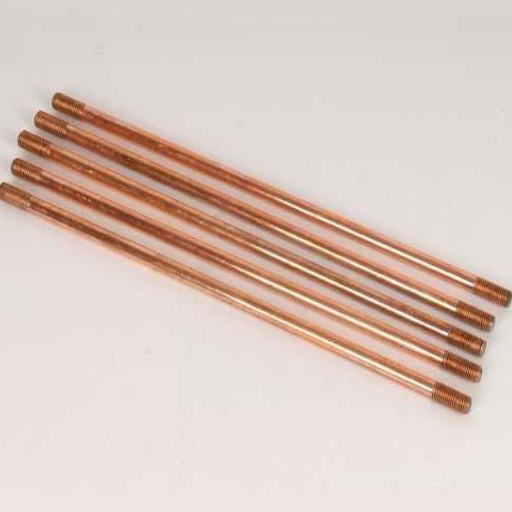
Copper-Bonded Ground Rods: Considered the most durable and excellent in conductivity, copper-bonded ground rods are steel rods with their surface coated in copper. These rods enjoy corrosion resistance and suitability for installation into most soil conditions that require long-term treatment for residential, commercial, and industrial purposes.
Galvanized Steel Ground Rods: Considered a cheap alternative, these rods are coated with zinc to prevent corrosion. Galvanized steel rods are better suited for use where the soil is non-corrosive, as their durability is lower compared to copper-bonded rods.
Stainless Steel Ground Rods: For enhanced corrosion resistance, these rods are preferred in the presence of aggressive soil conditions or chemical exposure. Their application is made in installations where longevity is a key requirement, such as in medical facilities and telecommunication systems.
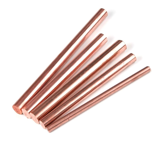
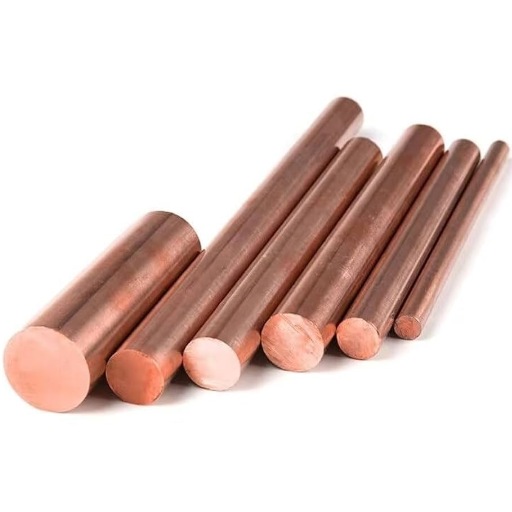
Solid Copper Ground Rods: Solid copper ground rods possess superior conductivity and resistance to degradation. They are typically used in highly corrosive environments and are costly, thereby limiting their practical applications to specialized installations, such as power substations or those involving high sensitivity.
The various types of ground rods serve distinct purposes, tailored to environmental considerations and performance requirements, ensuring that grounding systems can function safely and adequately in a range of applications.
Ground Rod Spacing Guidelines
The correct spacing is of utmost importance for proper grounding. Ideally, ground rods are placed at a distance equal to twice their length to avoid interference between their electrical fields. For example, if rods are eight ft. long, then they have to be spaced at least 16 ft. apart. This protects the fault-dissipating currents from entering the earth with much greater efficiency, while also increasing the system’s performance. It is always advisable to consult local codes and standards for any specific requirements regarding rod spacing.
NEC Regulations on Ground Rod Spacing
The National Electrical Code (NEC) provides very stringent guidelines to ensure safety and effectiveness in the installation of ground rods. From NEC Article 250.53(A)(3), it is said that if a single ground rod does not get resistance to ground within 25 ohms or less, then at least one more shall be installed. With the use of two or more rods, a distance of at least six feet has to be maintained between each pair. Nonetheless, to improve rendering and reduce interference between the conductive fields, the minimum recommended spacing between ground rods is generally equal to the length of the ground rods.
Hence, assuming the ground rods are 10 feet in length, they should be spaced at intervals of 10 feet or more to prevent overlapping electrical fields so that fault current may dissipate into the earth freely. Proper spacing provides a better, more reliable grounding system, which in turn poses fewer risks to the apparatus and personnel attached to it.
Always bear in mind that the soil conditions also affect the ground rod resistance. Resistant soil, such as sandy or rocky soil, may require other rods or longer rods for compliance. Strict codes can be enforced locally or by utilities; hence, always check the jurisdictional codes during planning and installation.
Recommended Distances for Ground Rods
The recommended separation between two ground rods is commonly equal to twice their length. So, if you are using 8-foot rods, a distance of 16 feet will be the minimum requirement. This separation ensures that the grounding systems do not interfere, keeping the overall resistance of the system to a minimum.
Research and industry practices suggest that placing grounding rods too close together can lead to their electrical fields overlapping and diminishing their effectiveness. The resistivity of the surrounding soil also plays a crucial role in determining the optimal spacing. In low-resistivity soils such as those with an abundance of clay, standard distances may well be adequate. In rocky or sandy terrains, however, which feature higher resistivity, the spacing must probably be altered, mainly increased, owing to the poor conductivity.
Multiple rods are sometimes connected via bonding wires in a grid system for better grounding. Standards, such as those outlined in the National Electrical Code (NEC), must be followed for both safety and operational reasons. Always follow approved engineering guidelines and codes that suggest proper installation for the specific site conditions.
Factors Affecting Ground Rod Spacing
Soil Resistivity: The primary factor that influences how far apart ground rods should be spaced is soil resistivity. The higher the resistivity of the soil, such as in dry, sandy, or rocky terrain, the farther apart the rods should be spaced to maximize it as a grounding system. For example, soil resistivity can vary dramatically, ranging from approximately 10 ohm-meters in moist clayey soils to over 1,000 ohm-meters in dry sandy soils. Proper spacing of the grounding system ensures that currents are dispersed effectively, thereby reducing the likelihood of causing interference or system failure.
Rod Length and Diameter: They do affect spacing; larger rods achieve better penetration into the earth. Should it be necessary to consider rod diameter relative to length, longer rods discharge better potentials into interfacial layers of lesser resistivity and tend to warrant wider separation. Shorter rods or those of smaller diameter must be placed closer together to provide a sufficient area for acceptable performance.
Electrical Load and Fault Current: Grounding systems are designed to accommodate electrical loads and fault currents. Where electrical loads are greater or the system is more prone to fault currents, the ground rods will need to be spaced more closely; this will facilitate the safe handling of excessive current levels without compromising operational functionality.
Environmental Conditions: Like temperature, moisture, and seasonal changes, the Earth’s response is also affected. Consequently, during the dry season, soil moisture decreases while its resistivity potentially rises. Although not a direct determinant of spacing, this is another argument for integrating an appropriate spacing and rod placement strategy to counter environmental fluctuations.
Code and Industry Standards: Codes and standards provide recommendations and prescriptions for correct ground rod spacing. For example, a typical recommendation is that the spacing not be less than twice the length of the rods to minimize interference between the adjacent electrical fields. Compliance with such professional standards guarantees both safety and operational functionality.
Taking all these factors into consideration will provide the best protection, along with regular testing and proper maintenance, to ensure continued compliance and performance.
Installation of Ground Rods
First, the process of installing ground rods starts by selecting a suitable location. The rod should be installed away from buildings and underground utilities. Using a hammer or specialized driver, the rod is driven vertically through the soil to maximize soil contact; ideally, the entire rod should remain under the surface, unless otherwise specified by local codes. Multiple rods, connected by a conducting wire, can be considered when dealing with challenging or rocky soil to improve grounding. The installation must comply with all applicable safety standards and local regulations.
Tools Required for Ground Rod Installation
Ground Rod – Essentially, copper-clad or galvanized steel rods measuring anywhere from 8 to 10 feet are made to serve the purpose of grounding.
Hammer or Ground Rod Driver – For manual installation purposes, a sledgehammer is often used. Alternatively, if one is keen on making the process efficient and quick, an attachment called the ground rod driver can be used with a power tool.
Shovel or Post Hole Digger- Prepares you to loosen any kind of compact soil or pre-dig holes where the earth is hard or rocky.
Wrench or Pliers – They will help secure the clamps with the best and most optimal assistance in ensuring tight connections between the ground rod and the grounding wire.
Grounding Clamps – High-quality clamps to firmly secure the grounding wire to the rod.
Grounding Wire – Copper wire of proper gauge for creating a safe and efficient electrical pathway.
Wire Strippers and Cutters – Provide excellent service in preparing and handling grounding wire during installation.
Safety Gear- Gloves, safety glasses, and sturdy boots: all of these will appropriately serve to protect you during the installation.
Such tools enable the safe, secure, and speedy installation of the ground rod, taking into account local safety and electrical standards.
Steps to Properly Install Ground Rods
Choose the Right Location: Identify a suitable location for the ground rod installation. The installation site must be at least 6 feet clear of any structure or foundation to avoid interfacing with existing electrical systems or hazards. Ensure that no underground utilities are present; contact the local utility services for a survey.
Prepare the Ground Rod: Select the appropriate ground rod in compliance with NEC standards. Generally, copper or galvanized steel grounding rods are used, with lengths ranging from 8 to 10 feet and a diameter of approximately 5/8 inch. Clean the surface of the rod to ensure good conductivity.
Drive the Ground Rod into the Ground: With the sledgehammer or a special ground rod driver, drive the ground rod vertically into the ground. Proceed with the use of a rotary hammer fitted with a ground rod driver attachment if the material is much harder, and it saves time. The rod must be driven so deep that it will be visible above the ground only for some inches.
Ensure Proper Depth: According to NEC standards, the rule states that an 8-foot ground rod in the ground is the minimum requirement for optimal conductivity and grounding ability. If it is impossible to achieve this depth due to soil conditions, consider using multiple rods that are connected and separated by at least 6 feet of space.
Connect the Grounding Wire: Attach a copper grounding wire with the correct gauge to the ground rod using an approved grounding clamp, ensuring a secure connection. The wire must extend from the rod to an electric service panel or any grounded system. A tight, corrosion-free connection is necessary for optimal efficiency.
Inspect the Connection and Protective Installations: Verify the connection to ensure it is secure and complies with local electrical codes. Where necessary, apply anti-corrosion compound to the ground rod connection for enhanced durability. For extra safety, cover any exposed parts of the rod or wire with a protective casing.
Test the Grounding System: Measure the ground resistance using a ground resistance tester or earth resistance meter to verify the effectiveness of the grounding system. The ideal resistance should be 25 ohms or less, although lower values are preferred for sensitive systems. When the resistance is higher, additional rods are needed.
Following these steps carefully, using high-quality materials, ensures the installation of ground rods that are safe, dependable, and code-compliant for all residential and commercial applications.
Common Mistakes to Avoid During Installation
An essential aspect of ensuring the safety and functionality of electrical systems is the proper installation of ground rods. Yet several blunders often interfere with the efficiency of an installation. Listed below are some of the issues to watch out for, as well as their possible effects:
Incorrect Rod Depth: One of the significant errors occurs when the ground rod is not driven far enough into the earth. Electrical codes tend to recommend that the rod be at least 8 feet deep for proper grounding. Inadequate depth may cause poor conductivity, especially in dry or sandy soils.
Poor Soil Consideration: Soil characteristics are equally important for the grounding system. Placing rods in highly resistive soil, such as in rocky or sandy terrain, without accounting for this resistance, can result in poor performance. This issue can be addressed by using chemically enhanced ground rods or by adding additional grounding points.
Poor Connection: Loose or corroded clamps degrade the effectiveness of grounding rods. This could also be destructive when inferior materials are used as they degrade over time, increasing resistance and eventually destabilizing the electrical systems.
Ignoring Resistance Testing: Failing to test soil resistance after installation is a standard error. Ideally, this should be under 25 ohms; for sensitive installations, such as data centers, a resistance of under 5 ohms is preferable. Ignoring tests may render the installation non-compliant and increase its susceptibility to failure.
Ignoring Rules for Multiple Rods: If one rod does not suffice as an effective ground, several rods spaced at least twice their length apart will be needed to substantially reduce resistance. Noncompliance with proper spacing and placement diminishes the benefits gained from having multiple rods.
Ignoring Environmental Conditions: Dry spells and frozen ground are examples of seasonal changes that can seriously weaken grounding systems. The installation of rods without thorough consideration of how environmental factors could influence long-term performance might lead to eventual problems.
By addressing these types of issues and adhering to industry standards and resistance values, contractors and installers can enhance the reliability and safety of ground rod systems in all applications.
Designing a Grounding System
First, to design a grounding system, the specific requirements of the application must be evaluated. Think of it as asking whether any given soil could fit into a particular grounding system design; one would consider soil resistivity there, as it has a strong effect on the grounding efficiency. Choosing ground rod materials that are both durable and corrosion-resistant, such as copper-bonded steel, would be key. The design must comply with all safety standards and regulations. With the installation complete, resistance values are thoroughly verified to ensure safety and that the system functions properly.
How to Design a Grounding System with Multiple Rods
Evaluate Soil Resistivity: Begin by measuring the soil resistivity using devices such as a four-point tester. This gives insight into the ideal spacing and depth of the ground rods needed to optimize grounding performance.
Select the Right Ground Rods: The materials used must be fully conductive and corrosion-resistant, such as copper-bonded steel and galvanized steel. These materials will make the rods strong and able to function well over time under varying environmental conditions.
Determine the Configuration: Lay out multiple rods according to the soil’s resistivity. Standard configurations include rods laid out in a grid pattern or spaced radially, with a spacing between each rod of approximately 2 to 3 times the rod’s length, to minimize mutual interference.
Install Proper Connections: The ground rods are best connected with high-quality clamps or welds to minimize resistance, ensuring that all connections are sealed against environmental interference, such as moisture.
Ensure Compliance with Standards: Adhere to local and international grounding standards, such as the National Electrical Code (NEC) or IEEE guidelines, to promote safety and ensure proper functioning.
Post-Installation Testing: Test the grounding using standard methods, such as the fall-of-potential test, to ensure the system has the required resistance values for the application, typically below 5 ohms. Any modification should be made if the resistance is too high.
Ensure the steps taken lead to the design of a grounding system that enhances the safety and reliable operation of electrical systems.
Soil Conditions and Their Impact on Grounding Design
Soil conditions are one overriding factor in determining the characteristics of a particular grounding system. Soil resistivity, the amount of moisture, temperature, and the presence of salts are some factors affecting the performance and design of grounding systems. Low resistivity soils, rich in moisture and minerals, provide better conduction and increase the effectiveness of the grounding system. High-resistivity soils, such as dry sand or rock, require additional measures, such as chemical backfill treatment or very long grounding rods, to achieve resistances at acceptable levels.
Seasonal variations, by altering moisture content or temperature, impact soil resistivity; ice-cold or arid soils tend to increase resistance and decrease grounding effectiveness. To address such matters, soil testing should be conducted before initial surveys, and the design should be modified accordingly. In the case of a challenging problem, this modification may involve incorporating multiple rods, conductive enhancement materials, or deep-well grounding. Grounding design must consider local soil conditions for safety, reliability, and regulatory compliance.
Working with Engineers to Optimize Grounding Systems
Collaborating with engineers on grounding excels only if it follows an open communication process and the sharing of essential data, such as soil resistivity readings and environmental considerations. Emphasizing an understanding of the design objectives, I can provide feedback on the practical aspects. Instrumental practical inputs might reflect the choice of materials or configurations adapted to the site. We design the system together to exclude any safety hazards; the expected outcome is that it is fully reliable and fits the actual project conditions.
Horizontal Grounding Rods
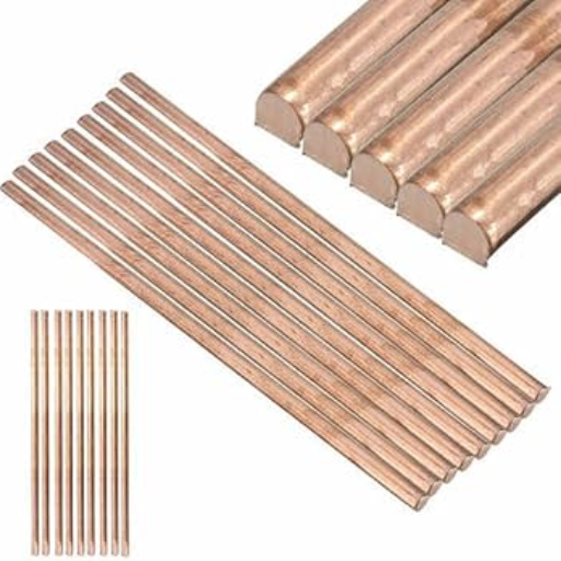
Horizontal grounding rods are generally preferred when areas are limited or when soil conditions do not favor vertical installation. These rods are inserted into horizontal trenches and provide a suitable alternative to grounding an electrical system. They are well-suited for electrical conductivity and corrosion resistance due to being made of copper or galvanized steel. Correct installation with uniform depth maintained throughout and adequate contact between electrodes and soil on all parts is necessary to have optimum performance.
When to Use Horizontal Ground Rods
Horizontal ground rods are best suited for conditions where soil properties, space constraints, or installation requirements prevent the establishment of vertical grounding. For example, vertical rods may not attain adequate depth for effective grounding in the presence of shallow bedrock, a high water table, or densely compacted soil. Horizontal rods thus constitute a viable option to be laid in trenches of uniform depth to achieve better performance.
Research has shown that horizontal layouts are more commonly applied to industrial plants, substations, or renewable energy systems, such as wind and solar farms. Industry literature reports indicate that a horizontal grounding system can achieve a level of resistance comparable to that of a vertical rod by utilizing longer rod lengths and ensuring better soil contact. A 10-foot-long horizontal rod, for instance, laid 2 to 3 feet beneath, can impart adequate grounding comparable to a vertical rod under favorable soil conditions.
Another consideration favoring horizontal ground rods is their flexibility in areas with residential and urban settings. It serves well in situations where a property has limited yard space or obstructions, such as underground utilities. For best results, engineers recommend using copper or copper-bonded steel due to its excellent conductivity and durability in soils, particularly in terms of corrosion resistance. Proper trenching depth and soil moisture content, with the use of grounding enhancement material (conductive compounds), further ensure system reliability.
Installation Techniques for Horizontal Ground Rods
Horizontal ground rods, if not installed properly, can significantly impact the performance of grounding systems and compromise safety. The first step involves selecting a suitable location that will sustain sufficient moisture and offer low resistivity for good electrical conductivity. Studies show that soil resistivity below about 100 ohm-meters is considered most efficient for grounding installations.
Trench Dug: The trenches must be dug into the ground to the specified depth, typically ranging from 18 to 36 inches, depending on local regulatory conditions and soil types. The deeper the installation is made, the less resistance it offers and the more protection it provides against environmental factors such as drying or freezing. Drying becomes more critical in freezing conditions, which enhances the effectiveness.
Material Preparation: Horizontal rods are primarily made of copper and copper-bonded steel, both of which are highly conductive, resist corrosion, and have a long lifespan. Ordinarily, horizontal rods ought to be half an inch thick, although bigger diameters are sometimes used for very heavy-duty applications. In some cases, the rods may be paired with conductive enhancement materials, such as bentonite clay or concrete additives, to enhance soil contact and reduce resistance.
Place and Connect Rod: The ground rod must be suitably positioned in the lower trench to assure constant contact with the soil. Rods should be laid in straight lines, separated at least twice their length from adjacent rods if multiple connections are required, to ensure minimal mutual interference. The rods are typically connected by exothermic welding or mechanical clamps to provide a good, permanent joint.
Backfilling and Compaction: After setting up the rod, the trench is backfilled with a mix of excavated soil and ground enhancement material. The proper compaction of soil is necessary to allow maximum contact between the rods and the surrounding earth, in reducing resistance and improving dependability with time.
Final Testing: As an essential finishing step, the test for any installation shall be conducted to verify effectiveness using measuring instruments such as a grounding resistance tester or a clamp-on meter. It is an international standard to maintain resistance to grounding below 5 ohms in general applications, but closer to 1 ohm may be required for critical infrastructure.
Following the provisions mentioned above, horizontal ground rod installations provide crucial low-resistance grounding, saving equipment and personnel while affording long-term durability in various environments.
Advantages of Horizontal vs. Vertical Ground Rods
Horizontal ground rods typically require spacing of at least twice the rod length. In contrast, vertical ground rods are spaced at least their driven length apart to minimize interference and achieve optimal resistance levels.
|
Parameter |
Horizontal |
Vertical |
|---|---|---|
|
Spacing Rule |
2x rod length |
1x rod length |
|
Installation Depth |
Shallow |
Deep |
|
Soil Contact |
Larger area |
Smaller area |
|
Best for |
Shallow soils |
Deep soils |
|
Interference |
Low if spaced |
Low if spaced |
Reference Sources
2. Analysis of the Design Calculations for Electrical Earthing Systems
3. Athens Seasonal Variation of Ground Resistance Prediction Using Neural Networks
Frequently Asked Questions (FAQs)
What is the recommended grounding electrode spacing?
The recommended grounding electrode spacing typically depends on local codes and regulations, such as NEC 250.53. Generally, a spacing of 10 to 20 feet between grounding rods is suggested to ensure the proper performance of the grounding system.
How do I properly install a grounding conductor?
To install a grounding conductor properly, ensure it is securely connected to the grounding electrode system. The conductor should be sized according to the NEC and should be buried in soil at a depth that prevents interference and damage from environmental factors.
What factors affect the impedance of grounding systems?
The impedance of grounding systems can be affected by various factors, including soil conductivity, moisture content, and the design of the grounding electrode. Regular testing and maintenance can help ensure that impedance remains within acceptable limits.
What is the sphere of influence in grounding design?
The sphere of influence refers to the area around a grounding electrode where the electrical potential is significantly affected by the grounding system. Understanding this concept is crucial for engineers when designing a grounding system to ensure adequate protection against lightning.
How can I determine the optimal location for grounding rods?
To determine the optimal position for grounding rods, consider factors such as soil type, moisture content, and proximity to nearby structures. It is essential to place rods in areas with low impedance to achieve optimal performance and safety.
How often should grounding electrodes be inspected?
Grounding electrodes should be inspected periodically to ensure they are functioning correctly. Regular inspections help identify any degradation or corrosion that may affect the effectiveness of the grounding system, especially after severe weather events.
What is the theory behind using three rods for grounding?
The theory behind using three rods for grounding is to create multiple paths for electrical current to dissipate safely into the ground. This design helps reduce the overall impedance and enhances the efficiency of the grounding system, especially in lightning protection applications.
What is the role of NFPA 780 in grounding systems?
NFPA-780 provides guidelines for the design and installation of lightning protection systems, including grounding requirements. Following these guidelines helps ensure that the grounding system is adequate for protecting structures from lightning strikes.