Boats have complex electrical systems to power everything from navigation lights to onboard electronics. Maintenance can be an issue regarding safety and performance while on the water. On the other hand, working with marine wiring can be a daunting task if one is unaware of the industry’s color codes, which are used as standards. These color codes are essential in knowing the wire’s purpose, making the correct connections, and, overall, avoiding some expensive electrical blunders. Through this article, we will explore various aspects of marine wire color coding, helping you understand its importance and providing practical tips to maintain the boat’s electrical system in good working condition. This article should be beneficial whether you are an experienced boater or just starting with your maritime adventures; it will provide you with the skills to stay safe and organized.
Introduction to Marine Wiring
In marine wiring, all components related to electrical connections and devices are integrated into the system for use in an aquatic environment. Essentially, this means marine wiring systems are designed to resist all the challenges that boating might throw at them, from moisture and salt to vibrations. Proper marine wiring ensures the correct and safe functioning of electrical systems on boats, including navigation instruments, lighting, and essential equipment. Therefore, delivering secure and reliable service on the water involves using high-quality marine-grade wires and ensuring all connections are clear and well-organized.
Importance of Marine Wiring
The electrical and wiring systems onboard vessels are essential for the safety, operation, and endurance of these vessels. Marine wiring differs from ordinary wiring in that it is designed to resist corrosion from saltwater, withstand vibrations, and tolerate high moisture levels typical of marine atmospheres. Tinned copper wire is a good example: this is a standard marine application wire that offers excellent resistance against oxidation and corrosion while maintaining wire flexibility and conductivity over time.
Hence, the proper installation of marine wiring is crucial to ensure the continuous operation of essential systems, including navigation equipment, communication devices, bilge pumps, and lighting. According to standards set by organizations such as the American Boat and Yacht Council (ABYC), all circuits must be sufficiently insulated, protected, and fused against electrical failures or fires.
Data continues to underscore the importance of this discipline in a marine environment. Most breakdown occurrences on a boat are typically caused by electrical problems, with corrosion accounting for nearly 70% of these failures in environments with high saltwater content. Regular checks and adhering to best practices, such as using heat-shrink connectors on terminal connections and circuit breakers on circuits, can go a long way in eliminating a vast majority of these electrical nuisances.
All said and done, marine wiring holds utmost significance because it directly relates to crew and passenger safety, as well as the vessel’s actual operational efficiency. Apart from reduced expenses on repairs, proper marine wiring installations and maintenance programs also promise greater reliability in adverse sea conditions.
Overview of Wire Color Code
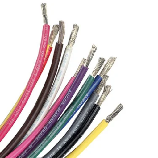
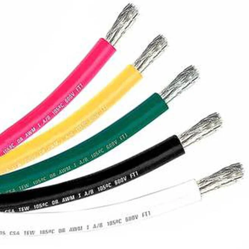
Wire color coding in marine wiring is a crucial aspect of safety, reliability, and convenience during maintenance and repair operations. Hence, the American Boat and Yacht Council developed standardized wire color codes describing the function of each wire in a vessel’s electrical system. Below are some commonly accepted color codes and their corresponding purposes:
Black: Usually in use for negative DC circuits.
Red: Positive, DC circuits, primarily the main feed.
Yellow (or yellow with a red stripe): Designates DC negative circuits and is increasingly replacing black in new installations to avoid confusion with an AC circuit.
Green or Green with Yellow Stripe: Exclusively for grounding wires, which provide safety for life and shock prevention.
White or White with Blue Stripe: Denote AC neutral wires.
Blue: DC lighting circuits or accessory power.
Orange: 120-volt AC wire between two switches in specific systems.
Standardizing these colors and their usage hence provides technicians with a means to trace wire connections and their intended purpose during troubleshooting easily. In the marine industry, it is highly likely to find a particular vessel, either by region or by type, that does not adhere strictly to ABYC standards. Therefore, knowing when to inspect and adhere to these standards will ensure a safe and functioning electrical system onboard. Correctly tagging and organizing wire bundles will go a long way toward clearing up any confusion that may arise during repair or upgrade work.
Common Applications in Boats
Electric power is essential on vessels to serve various functions that ensure safety, convenience, and efficiency. Primarily, they power navigation and communication systems, including GPS, chart plotters, radar, and VHF radios. The systems require a steady power supply to enable safe route planning, collision avoidance in offshore operations, and emergency communications.
In addition, there are lighting systems both inside and outside the boat. The navigation lights, deck lights, and anchor lights play a crucial role in enhancing visibility and ensuring compliance with marine regulations. LED lighting is gaining immense popularity because it consumes less electricity, lasts longer, and produces less heat, making it eminently suitable for marine applications.
These electrical systems also power the onboard appliances and other utilities, including refrigeration, electric stoves, air-conditioning units, and entertainment systems such as stereo systems or televisions. Thanks to recent advances in marine batteries and charging technology, including the lithium-ion battery, these appliances can operate reliably even during extended trips.
The bilge pumps and water-management systems are crucial to safety, as they operate to remove unwanted water from the bilge and reduce the risk of flooding. Many of them incorporate sensors and alarms that depend on the vessel’s electrical system to maintain propriety throughout the monitoring.
Additionally, today’s boats are increasingly equipped with solar panels and wind turbines to enhance energy independence and sustainability. These renewable power sources may help reduce the need for fuel to generate power and expand the range of electric propulsion systems.
Good progress in marine electrics continually optimizes these applications, enabling the installation of sophisticated, high-efficiency, and environmentally friendly systems aboard vessels, whose demands have been raised by the nature of modern boating.
Understanding Marine Wiring Color Code
Marine wiring color codes are crucial in ensuring that the electrical connections on a boat are safe and properly made. Generally, the color codes are standardized to signify the function the wire fulfills:
Black: Denoting grounds or negative connections.
Red: Supplying positive power for DC systems.
Yellow (sometimes yellow with stripes): AC system ground.
Green or Green Striped with Yellow: AC grounding wire.
Blue: Cabin lighting or general lighting circuits.
Brown: Bilge pumps or other auxiliary circuits.
From troubleshooting to maintenance and safety, the chances of getting miswires or electrical faults increase significantly if not followed well. In any instance involving an electrical system, always refer to a wiring diagram or a professional on that boat.
Significance of Each Color
Different colors in marine wiring ensure the safety, reliability, and proper functioning of a vessel’s electrical system. Let’s have a more in-depth look at the significance of each wire color:
Black – It is often the color used for DC negative wiring. Black wires play a vital role in completing the circuits inside the vessel’s electrical system. Consistency in their use will help in avoiding grounding errors and electrically hazardous situations.
Red- A color designated for DC positive wiring, red wires carry power from batteries or AC power sources toward other components, making it easier to troubleshoot or cross-wire negative circuits.
Yellow – A newer marine standard designates yellow as another negative DC line color in some cases to distinguish the DC negatives from the AC wiring systems, which use a different set of colors, thereby eliminating confusion.
Green or Green with Yellow Stripe – These are used for grounding wires only and protect against electrical faults by safely directing excess current to the ground. Proper grounding is crucial for protecting the vessel and its occupants.
Blue – The blue wires are associated with lighting circuits and are used in low-voltage marine navigation lights and other lighting systems. Having a separate color for lighting helps isolate lighting problems during maintenance or repair.
Brown- For circuits that engage the auxiliary systems necessary for a vessel’s operation and safety, and for those serving pump circuits, brown wire colors are administered for bilge and livewell pumps.
White – Concerning AC systems, white wires are neutral conductors, balancing the flow of current alongside the “hot” wire. The correct use of white wires contributes to the smooth and efficient functioning of connected devices.
In marine wiring, considerable emphasis is placed on adhering to these color codes to ensure optimal functionality and safety. Research, combined with insights from recent case studies by boating safety organizations, reveals that improper wiring, such as inadequate labeling or crossed wire functions, can lead to electrical fires or system failures. The use of these standardized colors protects the vessel’s system, facilitates its upkeep and inspection, and makes it easier to identify problems and comply with maritime safety standards.
ABYC Specifications for Marine Wiring
The American Boat and Yacht Council (ABYC) defines marine wiring standards to promote safety, operational efficiency, and reliability on all vessels. Major components addressed by these specifications include wire type and size, as well as installation practices, to ensure that electrical systems operate optimally in harsh marine environments.
One key ABYC standard prohibits the use of solid wires and instead recommends stranded copper conductors, which are more flexible and resistant to shock due to the constant vibration experienced on boats. Additionally, marine wiring must utilize tinned copper strands to resist corrosion from prolonged exposure to moisture and saltwater environments. For instance, corrosion resistance tests have shown that tinned copper wiring would considerably outlast its untinned counterpart in highly saline conditions.
Additionally, the ABYC specifies the ampacity requirements in terms of length and wire usage, ensuring that the wire can carry the current load without generating excessive heat. For instance, wires must be able to withstand 125% of the expected load, which provides a safety margin that enhances performance. The standards, accompanied by detailed tables, facilitate the precise selection of wire gauges and types by applying specific requirements related to voltage and distance, for example.
Another vital specification described by ABYC standards is insulation. Insulation must be flame-retardant and oil-resistant to prevent accelerated combustion or degradation. The circuit color codes are standardized and essential for identifying wires that are easy to trace. Black is used for DC negative wires, red for DC positive, and yellow for AC earth wires.
Installation practices in ABYC are based on ensuring that all connections are made using approved crimp terminals with heat-shrink tubing, which provides a watertight seal. Additionally, cables should be well-supported every 18 inches to prevent sagging or damage due to vibrations. Moreover, junction boxes, switches, and terminals should all be housed in weather-resistant enclosures.
Following the standards mentioned above not only fulfills the marine law requirements but also lowers the number of accident risks, increases the longevity of onboard systems, and provides a safer environment for all the passengers.
Types of Marine Wires and Cables
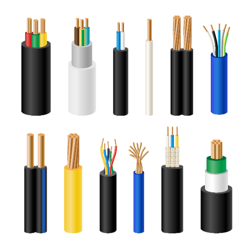
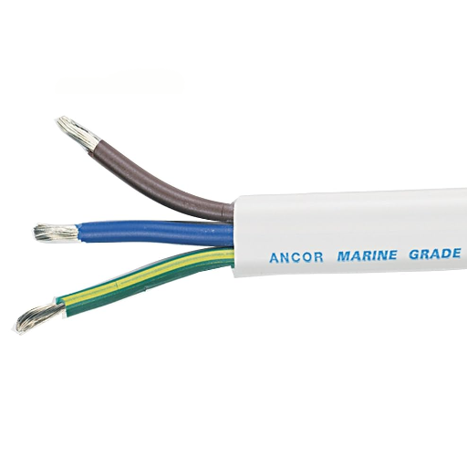
All marine wiring is designed to withstand harsh marine conditions while ensuring durability and safety. Some common types of marine wires and cables include:
Primary Wire: This is a general-purpose wire for low-voltage circuits, tinned to resist corrosion.
Battery Cables: These are heavy, flexible cables that connect batteries to an electrical system with high current capacity.
Bonding Wire: For grounding and protection against electrical interference, these wires remain sturdy and corrosion-resistant.
Coaxial Cable: Used for radio frequency signal transmission and thus serves communication and radar systems on board.
Multiconductor Cable: These cables, which have multiple insulated conductors, ease wiring for circuits that require more than one connection point.
Each wire or cable type has different construction specifications set by the manufacturers that enable them to resist various marine conditions, such as moisture, vibration, and corrosion. Hence, they offer reliability and safety.
Choosing the Right Boat Cable
A well-chosen selection of boat cables is essential for ensuring safety, longevity, and optimal performance. Start by considering what the wires will be used for: powering electronics, navigation systems, or lighting. Look for cables specifically designed for marine use, as they are generally built to withstand moisture, UV rays, oil, and corrosion. Select tinned copper conductors for enhanced conductivity and resistance to oxidation in marine environments. The cable wire gauge also needs to be able to carry the load with minimal voltage drops, considering the distance of the run. The cable insulation should also be rigid and meet marine-grade standards, as established by organizations such as ABYC or UL. Spending the extra time selecting the proper cable will ensure the appropriate functioning of the systems on your vessel in demanding marine conditions.
Differences Between Marine and Automotive Wiring
In marine wiring, everything is different — way different — from what someone would find in an automotive wiring setup. Marine wiring is designed to withstand harsh, saltwater environments and must have tinned copper conductors to prevent corrosion and oxidation, unlike regular bare copper conductors used in the automotive setup. The cables also feature thicker insulation, conforming to strict marine-grade standards such as ABYC or UL, and can withstand UV radiation, moisture, and abrasion. On the automotive side, wiring tends to be less rugged because road vehicles generally operate in a controlled environment with minimal exposure to elements that cause corrosion.
Another difference is that marine systems typically operate on 12V, 24V, or higher voltages for large vessels, necessitating the proper selection of wire gauge to prevent voltage drops due to the length of the wires. But automotive systems would mostly use 12V systems with short wiring distances. They also require proper grounding and bonding to prevent galvanic corrosion and further water intrusion, whereas automotive systems focus on chassis grounding. In general, marine wiring demands durability to ensure safety in the aquatic environment, while automotive wiring caters to the fast and streamlined needs of land vehicles.
Best Practices for Marine Wiring
Use Marine-Grade Materials: Tinned copper wires and marine-grade insulation are always used to resist corrosion in the marine environment.
Secure Connections: The connections will be crimped and sealed rather than soldered. This ensures that the connections remain secure, reducing the risk of failure caused by vibrations or moisture.
Proper Grounding and Bonding: Establish effective practices of grounding and bonding to prevent galvanic corrosion and enhance electrical safety.
Wire Sizing: The wires used should be of the proper size, according to the amps and distance, to minimize voltage drops and provide optimum service.
Circuit Protection: The installation of the fuse or circuit breakers should be made near the power source to protect the wiring against overcurrent damage.
Label and Organize Wiring: Wires should be clearly labeled and contained within organized harnesses or looms to lessen maintenance and troubleshooting efforts.
Seal and Protect: Waterproof connectors, heat-shrink tubing, or any other sealing measures may be used to keep water away from electronic connections.
Strict adherence to these best practices will ensure a marine electrical system approach that prioritizes reliability, safety, and longevity in demanding conditions.
Installation Tips for Safe Wiring
Choosing the Right Wire: Select marine-grade wire that is sufficiently insulated to resist corrosion and other damage, such as UV rays and temperature fluctuations. The wire gauge size must be appropriate for the current flow to prevent overheating.
Proper Routing: The wiring should be routed away from sharp edges, moving parts, and sources of heat that might cause damage or wear. Use grommets to protect wires when they pass through holes or bulkheads.
Secure All Connections: Use good-quality crimps and crimping tools designed for marine use. Never use household wire nuts for marine applications.
Avoid Overloaded Circuits: Never exceed the amperage rating of a circuit. Use circuit breakers or fuses to protect your system.
Test the System: Once the installation is complete, perform a thorough inspection and testing of all connections and circuits to ensure proper functioning and safety before using them.
By following these tips, you can establish a safe, efficient, and durable marine electrical system, thereby minimizing the risks associated with improper installation.
Maintenance of Marine Wiring
Routine servicing of the marine wiring system is undoubtedly worthwhile to achieve operational safety and efficiency advantages. Here is a set of brief tips provided by experts.
Inspect connections: Check for corrosion, fraying, or loose terminals. A corroded terminal can obstruct the flow of electricity, potentially leading to system failure. Always clean the terminals with a wire brush and then apply an anti-corrosion spray.
Look for damage: Check for any signs of damage, such as cracking in insulation, cuts, or exposed conductors. A damaged cable is a source of a short circuit and, in the meantime, becomes hazardous if left unattended.
Protect from moisture: Seal exposed wiring with waterproof heat shrink tubing or connectors approved for marine use. Moisture ingress can degrade electrical conductivity and lead to improper operations.
Regular inspections: Perform voltage, continuity, and load tests to ensure that electrical equipment is functioning correctly. Note any abnormalities that may indicate other problems that need attention.
Wire labeling and routing: Whenever a service line is installed, it must also be marked. Proper routing should be implemented to facilitate easier recognition in the event of troubleshooting or repairs. Organized wiring prevents accidental damage during services and also makes maintenance simple.
A routine of such maintenance would indeed maximize the lifespan of your marine electrical system, along with reduced downtime and repair costs.
Common Mistakes to Avoid
Neglecting Regular Inspections: If you fail to inspect your marine electrical system regularly, the slight wearing and aging of its components can go unnoticed and lead to relatively expensive failures. It has been established that periodic maintenance can reduce unexpected defect rates by approximately 30%, underscoring its significant role in prolonging the lifespan of the equipment in question.
Using Incorrect Wire Gauges: Using incorrect wire gauges in marine electrical systems is a common yet disastrous mistake. Undersized wires overheat while experiencing very high voltage drops, thereby compromising system efficiency and safety. For example, the consideration of using an undersized wire would cause voltage drops of over 10%, a level that intolerably affects the performance of sensitive electronic devices onboard.
Skipping Corrosion Protection: The corrosive nature of marine environments comes due to countless opportunities for saltwater assault. For instance, any connection not thus protected with corrosion-resistant materials or sealant compounds is bound to fail electrically. Such protection, on the contrary, could improve reliability by some 20%.
Improper Grounding: Poor or inadequate grounding only increases the probability of system malfunctions and electrical shock hazards. When grounding should be ensured through marine-approved ground wires, connections to the grounding bus must also be checked to maintain compliance with the standard and reduce electrical noise interference.
Overloading Circuits: This mistake is the most common one; although easy to avoid, it can cause various issues, such as tripping breakers or, even worse, the early deterioration of the wires themselves. Load calculation tools are, therefore, crucial for verifying that circuits are not being overloaded beyond their designed limits in amperes. For instance, a vessel operating at 80% or less of its circuit capacity will reduce the strain on the system over the long run.
If the above mistakes are kept in check while following best practices, one is sure to have a safer and more reliable system that will not result in downtime or repair expenses.
Where to Find Marine Wiring Color Codes
Marine wiring color codes are documented in ABYC (American Boat and Yacht Council) standards, which are universally accepted in the marine field. These standards specify the required colors of the wires for a particular electrical connection on a vessel. Additionally, various marine-specific wiring manuals and product handbooks carry color-code charts for consideration. Would you like to view these charts immediately? They are usually published on the websites of trusted marine suppliers and manufacturers. All of these reference points ensure you are following best practices and keeping your work safer.
Valuable Tools for Wiring Projects
For me, a few indispensable tools are always necessary to accompany a wiring project, ensuring that the job is done efficiently and safely. Wire strippers and crimping tools are my go-to equipment. Of course, it is advisable to have a multimeter nearby for testing various electrical connections. Heat shrink tubing and a heat gun are also essential items to have on hand for securing and insulating terminals. Using such tools has consistently contributed to excellent workmanship, and I can confidently say that I always adhere to all relevant industry standards.
Further Reading on Marine Wiring Specifications
Marine wiring specifications are guidelines designed to ensure the safe and reliable operation of electrical systems in aquatic environments. ABYC standards serve as an essential guideline for specifying marine-grade hardware to maximize resistance against corrosion and electrical failure. For example, conductors must be made of tinned copper and conform to UL 1426 standards to withstand saltwater and extreme conditions.
Wire sizes are chosen through a careful calculation of current-carrying capacity and voltage drop limits. The ABYC recommends a 10% drop for non-critical systems and a 3% drop for critical systems, such as bilge pumps or navigation lights. In some instances, a higher 10-gauge wire size may be warranted for a load drawing 20 amps over a 15-foot distance.
All terminals must be marine grade, with adequate insulation and strain relief to prevent failure due to vibration. Heat shrink tubing is often placed over these crimped connectors as further protection against moisture ingress and corrosion.
Fusing and circuit protection are paramount. Each circuit shall be protected by an appropriate fuse or circuit breaker rating, as close to the power source as possible. Ignoring such preventive measures can result in safety issues, including shorts or fires.
Marine wiring can, in principle, bear the provisions of these specifications, offering longevity and reliability in the most challenging marine environments. A detailed breakdown of systems and compliance standards, as outlined by ABYC (or its equivalent), may be desirable to have on hand.
Reference Sources
Frequently Asked Questions (FAQs)
Marine Wiring Color Code
What is the marine wiring color code system?
The marine wiring color code system is a standardized method used to identify electrical wires in aquatic environments. It helps ensure that electrical systems are installed safely and correctly, facilitating troubleshooting and maintenance. The colors used in the code indicate the function of each wire, such as power, ground, or lighting circuits.
How can I identify the wiring color codes for my boat?
You can identify the wiring color codes for your boat by referring to the American Boat and Yacht Council (ABYC) guidelines. These specifications provide a comprehensive chart that outlines the standard wire colors used for various electrical functions, helping you to trace wiring and avoid mistakes during repairs or installations.
What are the most common wire colors used in marine wiring?
The most common wire colors in marine wiring include black for ground, red for positive power, and yellow or blue for additional circuits. This color identification system is crucial for ensuring safety and efficiency in your electrical system, allowing for easy recognition of each wire’s purpose.
How does wire gauge affect marine wiring?
The wire gauge, measured in American Wire Gauge (AWG), affects the amount of current a wire can safely carry without overheating. In the marine industry, using the correct gauge is essential to prevent voltage drop, heat buildup, and potential electrical problems. Thicker wires (with lower AWG numbers) are used for higher current applications, while thinner wires (with higher AWG numbers) are suitable for lower current needs.
What is the importance of using tinned copper in marine wiring?
Tinned copper is preferred in marine wiring because it provides enhanced resistance to corrosion and moisture, which are common in aquatic environments. This type of conductor ensures better durability and longevity for electrical systems in boats, reducing the risk of failures and the need for frequent repairs.
How can I troubleshoot electrical problems in my boat wiring?
Troubleshooting electrical problems in boat wiring involves checking for loose connections, damaged insulation, or faulty components such as fuses or switches. Utilizing a multimeter can help measure voltage and resistance, assisting in identifying issues within the electrical system. Following the marine wiring color code can also help in tracing wiring and isolating problems effectively.
What are the requirements for marine wire insulation?
The insulation on marine wires must be moisture-resistant, abrasion-resistant, and capable of withstanding heat and vibration. These requirements ensure that the wiring can endure the harsh conditions of an aquatic environment, improving the safety and reliability of the electrical system in your boat.
What is the role of circuit breakers and fuses in marine wiring?
Circuit breakers and fuses are crucial components in marine wiring as they protect electrical systems from overload and short circuits. These protective devices interrupt the flow of current when it exceeds safe levels, preventing damage to wiring and equipment. Properly sizing these devices according to the marine wiring color code and specifications is essential for adequate protection.