








Understanding 4-Way Switches
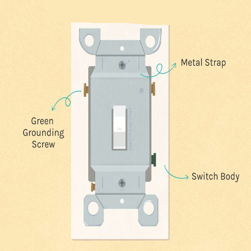
In electrical wiring systems, a 4-way switch is employed to operate a single light or a set of lights from two or more locations. Usually, it is positioned between two 3-way switches and wired in such a way that the current is allowed to flow through various paths, thus switching the light on or off at multiple places. Knowing the connections entails recognizing the four terminal screws on the switch—two for linking to the traveler wires incoming from one 3-way switch and two for the traveler wires going to the other. This setup results in a perfect circuit, making it possible to switch the lights on or off at different places very conveniently.
What is a 4-Way Switch?
A 4-way switch is an electrical switch that is used only with two 3-way switches to operate a single light or a group of lights from three or more different places. It is built with four terminal screws, out of which two are for the incoming wires (connected to one 3-way switch) and the other two are for the outgoing wires (leading to the other 3-way switch). The 4-way switch takes the traveler wires and reverses them, thus allowing the circuit to direct the current in the direction based on the positions of the switches. This wiring scheme is often employed in large rooms, corridors, or stairways to make the lighting control at various points more flexible.
How 4-Way Switches Work
A 4-way switch works as a mediator in a lighting circuit, being placed specifically between two 3-way switches. The main role of a 4-way switch is to switch the electricity between the two traveler wires, thus taking control of the current’s path depending on the positions of the switches. The 4-way switch has internal parts consisting of a number of mechanical contacts that shift between two different configurations. When that is done, the switch either gets one pair of terminals connected or it gets the traveler wire connections reversed, thus allowing or blocking the electric circuit. The whole system enables the operation of a light fixture from three or more places with no connection being broken at any moment. It is a setup that is usually seen in places like long corridors, big rooms, or staircases, where having the light turned on and off from different places is essential. The circuit is said to be in good condition and safe if its wiring and testing for continuity have been done properly.
Benefits of Using a 4-Way Switch
Key Advantages
Integrating a four-way switch system greatly increases lighting control comfort and flexibility in a given area. It allows users to control one light bulb from three or more different points, making it especially suitable for bigger places such as open-concept rooms, corridors, or staircases. This arrangement cuts down the number of trips to turn lights on or off, therefore increasing access and functionality for everyone. Moreover, 4-way switches help save electricity as they allow any point-connected light to turn off very easily, hence reducing the amount of energy used unnecessarily. If the 4-way switches are installed in the correct way, they will also play a big role in ensuring safety, especially in places with many entry points, by providing uniform and dependable lighting control. The implementation of such a design guarantees that the electrical circuit operates flawlessly and there are no interruptions.
Tools and Materials Required for a Four-Way Switch

Essential Components
- Four-way switch
- Two three-way switches
- Electrical cables (14/3 or 12/3, depending on circuit requirements)
- Wire connectors (wire nuts)
- Screwdriver (flathead and Phillips)
- Wire stripper
- Voltage tester
- Electrical tape
- Wall box(es) for switches
- Mounting screws
The proper tools and materials will guarantee the successful installation and operation of a four-way switch system. Always conform to the local electrical code and safety practices when carrying out the installation.
Essential Tools for Installation
- Turn Off Power at the Circuit Breaker: Take the necessary step of shutting off the power to the electrical circuit at the breaker first, before starting any work related to electricity. Then, with the help of a voltage tester, check to make sure that there is no live current passing through the wires. This measure is very important for safety.
- Prepare the Wiring: The installation of a four-way switch demands the use of two three-way switches located at each end of the circuit and a four-way switch or more in between. Depending on the circuit amperage, use either 14/3 or 12/3 electrical cables, and take care that the wire gauge is the same as that of your circuit. Prepare the wires for connection by stripping about ¾ inch of insulation off the ends of each conductor.
- Install the First Three-Way Switch: Put the first three-way switch at the place where the circuit starts. The power supply (live wire) should be connected to the black “common” screw terminal. The traveler wires should be attached to the two brass screw terminals on the switch, while ensuring that the wire color coding is followed.
- Wire the Four-Way Switch(es): Place the four-way switch at the location(s) where it is needed in between the two three-way switches. The traveler wires from the first three-way switch should be connected to one set of terminals on the switch; the outgoing traveler wires (going to the next switch) should connect to the other. Do not forget to adhere to the specific terminal configuration marked on the switch.
- Install the Second Three-Way Switch: At the circuit’s farthest point, connect the traveler wires to the same brass terminals as before and attach the black wire (load wire) to the “common” terminal. Make sure all screw connections are secure enough for good conductivity.
- Secure the Wall Boxes and Test: After finishing all the connections, carefully push the wired switches into their wall boxes and secure them with the mounting screws. Then, attach the faceplates, turn back on the circuit breaker, and test the system by switching on and off in various combinations to make sure it works.
- Final Inspection: Recheck all connections to make sure they comply with local electrical codes and check again for consistent and secure wiring. Put electrical tape over screw terminals as an extra safety precaution before sealing the boxes.
If you adhere to these steps and accurately employ the prescribed tools, the installation of a four-way switch system will be done effectively with guaranteed functionality and safety in compliance with the standards.
Wiring Materials Required
Material Checklist
The installation of a four-way switch system requires proper materials to be assembled beforehand. The Following are the main materials you must have:
- Four-Way Switches – At least one 4-way switch is needed for the system, along with 2 3-way switches for the circuit control at different points.
- Electrical Wiring – 14/3 or 12/3 standard wiring consists of three conductors (one black, one red, and one white) and one ground wire that connects the switches to the power supply. The wire’s gauge will depend on the circuit’s amperage requirement.
- Electrical Boxes – Sturdy switch boxes to provide safe storage for each switch; make sure the boxes are in accordance with local electrical codes.
- Wire Connectors – Either twist-on wire nuts or push-in connectors for a secure and reliable connection between wires.
- Electrical Tape – Premium-quality, heat-resistant tape for wire insulation and providing the connections with an extra layer of safety.
- Screwdrivers – A flathead screwdriver and a Phillips screwdriver to tighten the screws of the switches and to secure the fixtures.
- Voltage Tester – A non-contact voltage tester to check if the circuit is energized or not before starting the work.
- Mounting Screws – The proper screws to attach the switches and electrical boxes to the wall frames.
- Circuit Breaker – Make sure the right breaker is present on the electrical panel for the new wiring run to be accommodated.
The above-mentioned materials can help in ensuring that the wiring system is effective and safe both during and after installation.
Safety Equipment
Critical Safety Gear
Whenever electrical work is performed, it is crucial to use the right safety gear to eliminate the danger and, at the same time, meet the safety standards. The following tools are very important:
- Insulated Gloves – Very good, top-quality, electrically insulated gloves that are designed for the circuit’s voltage level. These gloves are a safeguard against accidental electric shocks that may occur during the installation or repair process.
- Safety Glasses – Safety glasses that are certified by ANSI and will protect each eye from pieces of material, sparks, or the involuntary exposure to the electric parts.
- Voltage Tester with Audible Alarm – A non-contact voltage tester that is very dependable with an audible and visual alarm to confirm that the circuits are not energized before the work is started, thereby giving an extra safety layer.
- Rubber-Soled Shoes – Footwear that is non-conductive and will reduce the risk of electric current passing through the body, and also provide better ground insulation.
- Fire-Resistant Clothing – Clothing that is made from materials that are flame-retardant, for example, arc-rated protective wear, to protect against the possibility of being burned by electrical arcs or sparks.
- Hard Hat – A hard hat that is strong, insulated, and will protect the head from objects falling, and also give extra resistance against incidental electrical contact.
The use of this complete list of safety gear will cut down the danger that comes with doing electrical jobs greatly, thus creating a safe workplace. Remember to check all safety equipment for damage or wear before using it to guarantee that it will work at its best.
Wiring a 4-Way Switch
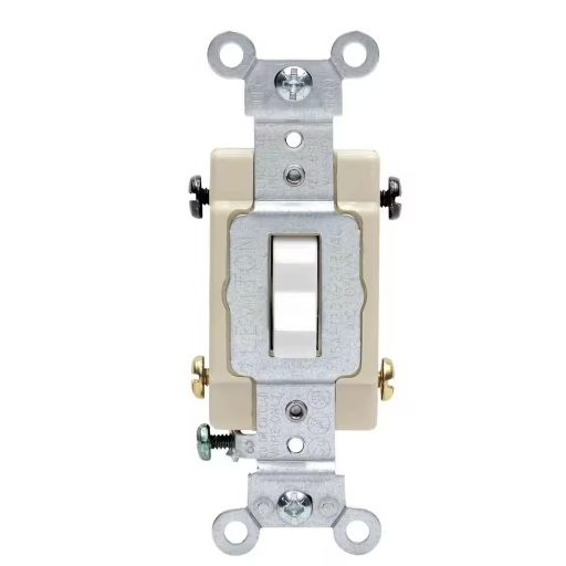
The process of wiring a 4-way switch can be broken down into the following steps, which must be observed:
- Turn Off Power – Safety first; thus, it is important that the power to the circuit is switched off at the breaker box.
- Understand the Configuration – The assembly of the 4-way switch system consists of three basic components: the two 3-way switches and the one 4-way switch, plus the wires that connect them.
- Identify Wires – Make sure there are four wires available at the 4-way switch site, consisting of two traveler wires coming from one 3-way switch and two traveler wires going to the other 3-way switch.
- Connect the 4-Way Switch – To a set of terminals on the 4-way switch, join the two incoming traveler wires. Next, attach the two outgoing traveler wires to the other pair of terminals. For easier identification, the terminals are usually labeled “in” and “out.”
- Make Connections Secure – Tighten securely all screws of the terminal and check for the presence of any wires that may short-circuit and cause malfunction.
- Complete the Circuit – Go back to the 3-way switches and check that their connections correctly join the hot wire (power source) with the load wire (to the lamp or device).
- Test the Setup – Turn on the power again and test all the switches to ensure they are functioning correctly. Any switch must be able to turn on or off the light or device.
Always check that the wires’ colors and configurations comply with the electrical code in your area and, if in doubt, do not hesitate to ask an electrician for help.
Understanding the Wiring Diagram
Decoding the Wiring Diagram
A wiring diagram is a comprehensive and systematic visual representation of an electrical circuit. It emphasizes the various connections among the components like switches, wires, power sources, and loads in a way that is easy to understand and follow. When decoding a wiring diagram of a 3-way switch configuration, it is necessary to point out the following:
- Power Source – This indicates the point where the circuit is supplied with electrical energy, normally illustrated as a line marked “hot” or “line.”
- Switch Connections – There are terminals in a 3-way switch for the common wire (preferably connected to the hot or load wire) and traveler wires, which allow switching control among the locations.
- Load Connection – This is where the circuit ends, for example, a light bulb that is controlled by the switches.
- Neutral Wire – Usually represented alongside the switches, this wire takes the current back to the power source, completing the circuit.
- Ground Wire – Shown for safety, this wire connects every device to the electrical ground.
Careful examination of the wiring diagram will help you to make sure that all the connections are correctly aligned during installation. It is very important to follow all the local electrical codes and best practices to avoid faults. If the diagram is not clear or is vague, then look for extra resources or get a certified electrician to clarify the issue.
Steps to Wire a 4-Way Switch
If the wires connecting a 4-way switch are in the right way, it guarantees that a luminaire can be controlled from three or more different places without any inconvenience. Provided below are the steps for installation, which are very detailed and also authoritative:
Get to Know the Parts
The 4-way switch setup consists of a total of four switches: two 3-way switches, one 4-way switch, and the related wiring. The 3-way switches are installed at the ends of the circuit, while the 4-way switch is placed in the middle. This kind of circuit requires a neutral wire, traveler wires, and a ground connection for the lighting system to be safe and to comply with the local electrical code.
Seal Power Off at the Circuit Breaker
Before doing any electrical work, get the appropriate breaker and turn off the power to the circuit. Then, using a circuit tester, check that the switch or wire locations are completely dead.
Make Connection at the First 3-Way Switch (Supply Side)
Start with the first 3-way switch. Connect the line (hot) wire coming from the power source to the black (common) terminal of the switch. The two traveler wires (generally red and black) should be attached to the switch’s remaining traveler terminals. Take care that the connections are not loose.
Fit the 4-Way Switch
At the 4-way switch’s location, the first 3-way switch’s traveler wires are to be connected to one 4-way switch’s pair of terminals. The other corresponding pairs of terminals will receive the traveler wires that are going toward the next switch. The terminals can often be identified by markings, so make sure to check the labeling to comprehend the connections accurately. If the 4-way switch can be connected by either screw or push-in, then always use the screw terminals because they are more reliable.
Make Connection at the Second 3-Way Switch (Load Side)
Connect the two traveler wires to the traveler terminals of the switch at the last 3-way switch. Next, wire the load (to the light fixture) wire to the black (common) terminal. Then, the ground wire should be connected to the green ground screw.
Make a Connection at the Light Fixture
Connect the load wire to the hot terminal of the light fixture. The neutral (white) wire from the fixture should connect to the neutral wires running from the circuit. Tighten all connections and cover with wire nuts.
Do Circuit Testing
After checking all connections, turn the power back on at the circuit breaker. Operate the switches to ensure they work correctly and the light fixture can be controlled from each location smoothly. If the circuit does not work as expected, turn the power off and check the wiring for mistakes or loose connectors.
To have a 4-way switch system properly wired, it suffices to stick to the prescribed steps and to also observe the rules set forth by the National Electric Code (NEC). In case of any doubts or difficult installations, it is better to have a licensed electrician give you a hand.
Common Wiring Errors to Avoid
Miswiring the Traveler Wires
Misconnecting or crossing the traveler wires is one of the most frequent mistakes made during 4-way switch wiring. The traveler wires should be in a proper arrangement, going from the first switch to the second and then to the third switch; if not, it could happen that the switches will not work at all. Always mark the traveler wires in a way that they can be easily spotted and check connections at each switch.
Failure to Properly Connect Ground Wires
Ground wires are essential for electrical safety, but they are often the last ones to be considered or poorly connected. It is important to have all the ground wires of the switches and junction boxes in the system properly connected and thus avoiding possible electrical shocks and hazards.
Using the Wrong Wiring Configuration
Misidentification of the “line” (power source) and “load” (fixture) terminals can result in a switch that does not function. Be sure that the line is connected to the right terminal of the first switch and that the load is connected correctly on the last switch. Having a wiring diagram will be really helpful in minimizing this mistake.
If you do not face these problems and verify your connections with a correct wiring diagram, you will be assured of a problem-free operation of your 4-way switch system.
Installing the 4-Way Switch
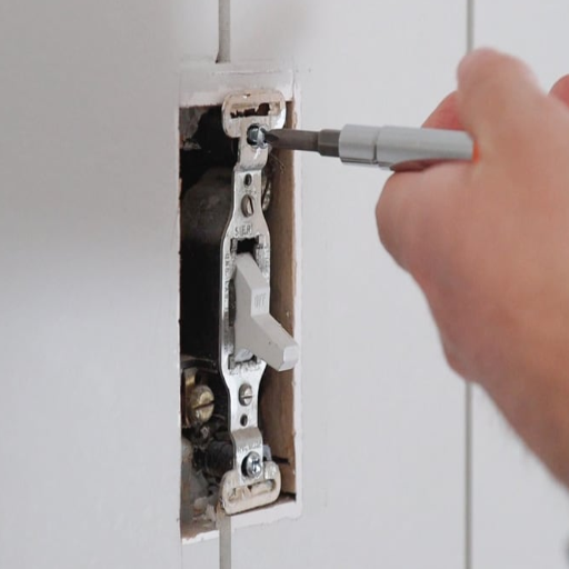
- Turn Off the Power: Find the circuit breaker that feeds the switch system and power it off to eliminate any risk during the installation process.
- Prepare the Wiring: Recognize the present wires, which should include the line (power source), the load (light or fixture), and the traveler wires. Check wire labeling for precision and make sure all wires are properly uncovered and have access.
- Install the First Switch: The line wire is to be connected to the common terminal of the first switch. The traveler wires are to be attached to the other terminals as per the wiring diagram.
- Wire the 4-Way Switch: Identify the 4-way switch in the circuit (it is in the middle of two 3-way switches). Run the traveler wires from the first 3-way switch to one side of the 4-way switch, then the traveler wires to the second 3-way switch on the other side.
- Connect the Final Switch: Join the traveler wires of the 4-way switch to the similar terminal of the second 3-way switch. The load wire is to be connected to the common terminal of this switch.
- Test the System: Bring back power at the circuit breaker and test the switches to make sure that they can turn the fixture on and off as intended. Also, check if the light is controllable from all switch locations.
If you diligently observe the steps and constantly compare with a wiring diagram, you can easily come up with a trustworthy and functional 4-way switch configuration.
Preparing the Electrical Box
The proper preparation of the electrical box is very important for having a safe and effective wiring installation done. The first step is to cut off the power to the circuit that you are working on at the breaker panel, and then use a voltage tester to check that there is indeed no power present. The next step is to make sure that the electrical box you are using is roomy enough to fit all the wires and connections without straining them, and at the same time, making sure your box corresponds with pole codes; normally, an existing box can be replaced with one that is bigger if that’s the case.
The next thing is to carefully strip the insulation from the ends of the wires with the help of a wire stripper – see to it that the conductors are not damaged. Next, inside the box, arrange the wires according to their functions—like ground wires, neutrals, travelers, and load wires—and if there is a grounded metal box, then attach the ground wire to the grounding screw of the box. Use still wire connectors or wire nuts to cover and fasten the connections, and also make sure there is enough space left for routing without overcrowding or torturous bending.
When you are retrofitting or working with older electrical boxes, first check for any indicators such as damage, rust, or wear, etc. that could reduce the system’s strength. If it is the case, then switch to a newer box that meets the current electrical codes. By carrying out these measures, the electrical box will be completely ready for a professional and secure installation.
Connecting the Wires
Identifying the wires correctly is the first step to connecting them. Most often, the hot wires are red or black, the neutral ones are white, and the ground wires are either green or bare copper. To start, you will need to strip the wire ends with the wire stripper, taking off about ¾ inch of insulation. Then, proceed by twisting together wires of the same type – hot to hot, neutral to neutral, and ground to ground – in a clockwise direction using lineman’s pliers. For securing the wires, place a wire connector (e.g., a wire nut) over the ends and twist the connector until it is tight; this will also ensure that no bare wire is exposed.
If there is a ground connection, attach the ground wire to the grounding screw inside the electrical box if that is applicable. For devices like outlets or switches, the hot wire goes to the brass screw, the neutral wire goes to the silver screw, and the ground wire goes to the green screw. All the terminal screws should then be tightened securely to make a solid connection. Confirming all the connections is the next step, and carefully pushing the wires back into the electrical box should follow, making sure there are no protrusions that could result in accidental contact or damage. This method guarantees reliable electrical performance as well as compliance with safety standards.
Securing the Switch
For switching security, initially, position the electrical box in accordance with the switch’s mounting holes. Fix the switch tightly using the provided screws, and make sure that the switch is not higher or lower than the box so that there are no gaps left that might get dirt in. Make sure the screws are not too tight; if that happens, the switch might get damaged, or even worse, the threads may get stripped. Always entwine the wires properly or use some insulation before turning the power back on; this action will prevent a short circuit. After the installation, put on the faceplate, the torquing of its screws would be just enough to make the plate level and yet not cause any cracking or warping of it. Check the installation by gently toggling the switch to feel the operation without any resistance. This is a way of confirming the switch is firmly installed and can be used safely.
Testing Your 4-Way Switch Installation
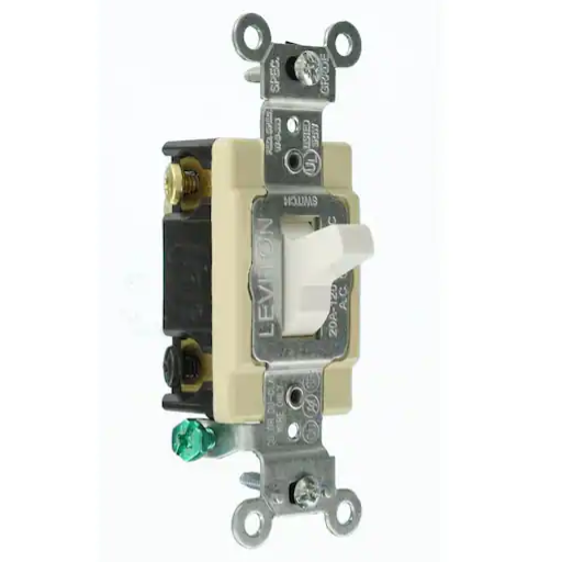
You are instructed to test your installation of the 4-way switch by following these steps:
Testing Procedure
- Restore Power: Switch on the circuit breaker to deliver the power to the switch.
- Check Each Switch: Turn on and off all switches connected in the circuit, one at a time, and in different combinations. Make sure that the light or device connected is correctly turned on and off, irrespective of the switch used.
- Inspect for Issues: Check for delays, flickering, and inconsistent operation. In case of any problem, switch off the power and inspect the wiring connections again.
Through proper testing, the 4-way switch system can be confirmed to be working properly and safe for regular use.
How to Test for Proper Functionality
To testify that the 4-way switch system is functioning properly, one should follow the steps below:
Switch Verification
With the power supply still on, check each switch of the circuit one after another and then in combinations. Toggle the switches varyingly to ensure the light or device that is connected responds correctly (turning on and off without any failures) through all switches in any order.
Consistency Inspection
While using the switches, look out for any delay, flicker, or intermittent behavior that may indicate inconsistency in operation. The same operation across all switches is of utmost importance.
Look for Connections if Needed
In case of any inconsistencies or malfunctions, turn off the circuit breaker first in order to cut off power to the whole system. Then, redo all wiring connections to ensure they are tight, in correct positioning, and in accordance with the circuit diagram.
Final Test
After verifying the wiring is intact, turn the power back on and do a final round of operating all switches to confirm that the system is still functioning consistently and without errors.
When you systematically perform these steps, you can rest assured that the 4-way switch system is safe and efficient, and that it is operating according to specifications.
Troubleshooting Common Issues
I usually start teasing out common problems by looking for loose or disconnected wires since they are frequently the main reason why systems malfunction. After that, I check the voltages at the primary points of the circuit to see if there are any differences or irregularities. If the issue still continues, I look for damaged or overheated components and replace the parts that aren’t working properly. Lastly, I turn to the system’s manual for error codes or special diagnostic steps to make sure that all possible problems are dealt with in a systematic and quick manner.
When to Call a Professional
Calling a technical expert is necessary in case the difficulty of the problem exceeds your technical abilities or when safety is of utmost priority. In the case where the system consists of high-voltage parts, needs special tools, or very sophisticated diagnostics that only an expert can do, it is better to have an expert always around to mitigate the risks. Furthermore, issues that keep happening and no amount of troubleshooting has helped may be indications of underlying problems that need a professional’s attention. If the system’s warranty is still in effect, then manufacturer-authorized repairs are usually needed so that the warranty will not be invalidated. Lastly, vague error messages or breakdowns in sophisticated systems such as electronic devices that can be programmed or connected to a network are meant for certified technicians only since they have the required tools, support from the manufacturer, and the right to access the proprietary information.
Safety First: Always remember that working with electrical systems can be dangerous. If you’re unsure about any step in the installation process, consult with a licensed electrician. Proper installation ensures not only functionality but also the safety of everyone in your home or building.
Reference Sources
Frequently Asked Questions (FAQs)
What is a 4-way switch, and how does it work?
A 4-way switch is an electrical device that you can use to control one light from three or more different places. It enables the various switch positions to turn the light on or off by working with two 3-way switches. The incoming wires connect to the switch, and the outgoing wires lead to the light fixture in a 4-way switch with two sets of terminals.
How do I wire a 4-way switch?
To wire a 4-way switch correctly, you must connect the different wires correctly. The first step in the process is to connect the power source to the first 3-way switch. Next, you must connect the red wires to the appropriate terminals at the 4-way switch while running wires to it from there. At last, connect the output wires from the 4-way switch to the second 3-way switch, and then to the light fixture.
What switch wiring help do I need for a 4-way switch installation?
For an effective 4-way switch installation, the wiring layout must be understood. The power source, the light fixture, and the required wires should be identified. You may be able to make the installation process simpler and faster by referring to wiring diagrams and getting professional advice.
Can I use dimmer switches with a 4-way light setup?
Dimmers can be used in a 4-way light setup, but specially designed dimmer switches for 4-way configurations are required for this setup. Make sure the dimmer switch is compatible with the other switches in the circuit and can handle the load for the best results.
What should I do if I encounter trouble with my 4-way switch installation?
If you run into problems while installing your 4-way switch, start by double-checking the wire connections to ensure they are secure. Next, if the light does not turn on or off as expected, check if the switches are in the right positions. If still no success, contact a professional electrician for help.
How can I achieve fast installation of a 4-way switch?
To install a 4-way switch quickly, first organize the entire installation process and gather the necessary materials. A clear wiring diagram is vital for this. Keeping all necessary tools and components, such as electrical tape and wire connectors, will help you finish the task efficiently. Also, working in an orderly manner will assist in avoiding mistakes and, therefore, will allow installation time to be reduced.
What types of light switches are used in a 4-way configuration?
A 4-way configuration typically includes two 3-way switches and one or more 4-way switches. The 3-way switches supply power, while the 4-way switches permit more than two switch positions to control the light fixture. This combination makes it possible to control lighting from more than one place.
Is it possible to install a Z-Wave switch in a 4-way light setup?
Definitely, a Z-Wave switch can be installed in a 4-way light setup. However, confirm that the Z-Wave switch supports a 4-way configuration and that you are following the wiring instructions given by the manufacturer. Moreover, integrating smart technology will give you improved control over your lighting and allow you to operate it remotely.