When it comes to optimizing the efficiency and performance of a solar energy system, knowing how to wire solar panels involves defining effective strategies. How you decide on series versus parallel wiring can dramatically change the system’s voltage, current, and energy output. Functionality and appropriateness for specific uses would either be enhanced or inhibited. This article aims to analyze the pros and cons, as well as the advantages of both wiring methods, to determine their differences, diverse applications, and implications. Whether you’re a homeowner installing a do-it-yourself solar panel system or an engineer refining your skills, you’ll gain the insight and information needed to harness the immense power stored in your solar panels optimally.
How Do You Wire Solar Panels in Series?

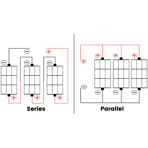
To achieve series wiring of solar panels, join the positive output of one panel with the negative output of the subsequent panel. Continue this with all the panels in the series. This configuration enhances the overall voltage of the system while maintaining the current at the same level. For instance, if each panel generates 12 volts and five amps, two panels wired in series would produce 24 volts and five amps of current. This approach is very effective in scenarios where higher voltage is needed, for instance, with grid-connected inverters or when cables have to be run over long distances. As always, check your inverter requirements and follow all safety procedures during mounting.
What is a Series Connection in Solar Panels?
The series configuration for solar panels involves connecting the positive terminal of one panel to the negative terminal of the next panel. This method raises the total system voltage while maintaining the same current as that of one panel. It is often utilized in applications where higher voltage is needed; for example, to increase compatibility with some inverters, reduce losses over long-distance transmission, or decrease heat loss during extended cable runs. Careful planning and compliance with safety guidelines are essential when configuring panels in series.
Advantages of Series Configuration for Solar Panels
- Increased Voltage Output: The overall voltage increases when solar panels are connected in series, which is advantageous for high-voltage inverters and efficient energy transmission over long distances.
- Reduced Power Loss in Cables: For the same power output, the current is lower in higher voltage systems. This dramatically minimizes resistive losses in the wiring.
- Compatibility with MPPT Controllers: Most charge controllers with maximum power point tracking (MPPT) work best at higher input voltages, making higher series configurations the best option.
- Less Complex Work: Compared to parallel configurations, series configurations require fewer connection points, which minimizes complexity and lowers the risk of faults.
- Scalability: Expanding a solar system is made easy with series configurations, as additional panels can be added to increase voltage without significantly redesigning the existing system.
- Cost-efficient: MPPT configurations allow for lower material costs and simplified installation requirements because thick and heavy-gauge wires are less common in higher-voltage systems.
Step-by-Step Guide to Wire Solar Panels in Series
- Inspect the Solar Panels: Start by checking the panels to use them in series wiring solar configurations. Inspect voltage and current ratings to verify all panels are uniform.
- Gather The Necessary Tools And Materials: create a checklist for starting, including a multimeter, connectors of the correct rating, wires, and hand protection such as insulated gloves.
- Identify the Positive and Negative Terminals: Every panel must be fitted with identifying markings for the positive and negative terminals (+ and –) before connecting the solar panels.
- Connect The Panels In Series: The positive terminal of the first panel should be connected to the negative terminal of the next panel while observing the shading impact of the first panel. Repeat until all panels are in series.
- Verify Connections: Check the total output of the connected panels with a voltmeter; they should not exceed the total voltage of unconnected panels.
- Secure The Wiring: Tighten not only all insulations to exposed electrodes but also all insulations to the connections. Maintain wires taut with the help of cable clips or ties to withstand movement during operation.
What is the Process to Wire Solar Panels in Parallel?
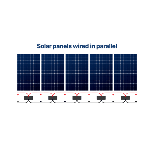
Understanding Parallel Connection for Solar Modules
A parallel connection for solar modules is one where the positive terminals from all panels are wired together, and the negative terminals are wired together. This method increases the total current output at a constant voltage, making it best for systems with high current and low voltage requirements. To connect solar panels in parallel, set up wiring using solar connectors designed for parallel wiring, also known as branch connectors, to join terminals of equivalent polarity in both series and parallel. Make sure the connections are tight and insulated; otherwise, energy could be lost and damage could occur. System specifications must be double-checked, including the solar charge controller’s maximum amperage, to ensure compatibility with the higher current.
Benefits of Parallel Wiring in Solar Installations
- Enhanced Reliability: As long as the remaining panels function, a balanced energy flow will always be maintained, even if one panel fails or becomes shaded.
- Higher Current Output: Ideal for systems requiring high current, Increased Current is better suited for given parallel wiring since it meets the overall current output while preserving the voltage of individual panels.
- Scalability: Expanding the solar array is made easier with parallel configurations since additional panels can be easily integrated into the system without significantly modifying the overall voltage.
- Support for Low Voltage Systems: Auxiliary Parallel Wiring allows for optimal performance in low-voltage environments, which cater to most solar systems designed for residences.
- Reduced Risk of Overvoltage: The risk of damaging highly sensitive parts due to overvoltage scenarios is reduced when using parallel wiring, as the system’s voltage remains constant.
Instructions for Wiring Solar Panels in Parallel
- Gather the necessary equipment: Verify that you have the required parts, such as solar panels, connecting wires, branch connectors, a charge controller, and a battery bank.
- Inspect Solar Panels: Check that every solar panel has the same voltage rating to permit parallel wiring.
- Connect Positive Terminals: Use branch connectors to combine the positive terminals of the solar panels. A single positive output connection is achieved at this stage.
- Connect the Negative Terminals: Repeat this step for the negative terminals of all the solar panels. Using branch connectors, combine them to create a single output connection.
- Merge to Charge Controller: The positive and negative output connections can now be connected to the charge controller at their respective input terminals.
- Connect the Charge Controller to the Battery Bank: The load terminals of the charge controller can now be connected to the batteries; make sure you do not reverse the polarity.
- Test the System: The entire system can be considered operational if the voltage and current readings at various positions match what is expected for the designed functionality.
Series vs Parallel: Which Wiring Method is Better for You?
Comparing Voltage and Current in Series and Parallel Wiring
| Parameter | Series Wiring | Parallel Wiring |
|---|---|---|
|
Voltage |
Divided among the components proportionally |
Same across all components |
|
Current |
Same through each component |
Divided based on branch resistance |
|
Resistance |
Total = Sum of individual resistances |
Total = Reciprocal of individual resistances |
|
Failure Impact |
Entire circuit stops if one fails |
Other components keep functioning |
|
Wiring Complexity |
Simpler, fewer wires needed |
More complex, more wire needed |
|
Connection Type |
Single path for current |
Multiple paths for current |
|
Applications |
Used in old lamps; voltage stepping |
Used in homes; consistent device voltage |
|
Current Flow |
One path only |
Multiple branches |
|
Voltage Drop |
Adds up across components |
Same for every branch |
|
Maintenance |
Requires full circuit checks |
Easier to isolate issues |
Impact of Shading: Series vs Parallel
The way circuits are wired, either in series or parallel, determines how shading affects performance in any electrical circuit.
- Series Circuits: As current is the same throughout the circuit, shading affects the whole circuit. A shaded area diminishes current for the entire circuit, causing an overall reduction in performance. For instance, in photovoltaic systems, shading one panel in a series array severely diminishes energy output across all panels.
- Parallel Circuits: Shading impacts a specific area of a circuit since current moves freely through each branch. A shaded area or component only performs poorly within its branch while the rest of the circuit operates well. This configuration has less impact on shading performance compared to the series configuration, particularly when one panel is shaded.
Catering to these disparities is primary in optimizing circuit performance to increase operability in areas where shading may occur.
Choosing Between Series and Parallel for Different Solar Projects
When determining options for solar projects, considering series or parallel circuits, the choice depends on the specific system’s needs. For applications where the voltage needs to be maximized, series circuits are the best option. This is the case for long-distance power transmission or in systems using high-voltage inverters. A clean environment could also use parallel circuits, since they work best where shading or partial obstructions are dominant. This guarantees consistent performance by isolating the impact of the shaded components. A mix of series and parallel configurations is preferred for most residential systems exposed to variable conditions, as it offers optimal efficiency while maintaining reliability.
How Does Solar Panel Wiring Affect Voltage and Current?
Understanding Voltage in Series and Parallel Configurations
The voltage gauge measures power, and when solar panels are wired in series, the power increases while the rate remains static for a single panel. This is helpful as the voltage of each panel is added together. For instance, connecting three 12V panels in series will yield a total voltage of 36V. However, when the solar panels are arranged in parallel, the total rate of power (amps) increases, while the voltage output remains static for a single panel. This occurs because the power produced by each panel combines, as is the case with three 5A panels wired together, which will yield a total current flow rate of 15A. Knowing these configurations is helpful while creating systems that require a definite voltage and current.
How Wiring Affects Current in Solar Systems
The configuration of solar panels affects the current flow within a solar system. For an increase in total current, solar panels can be connected in parallel. For instance, if each panel produces 5A, three panels in parallel will yield a total of 15A. This is crucial for the wiring of your solar panels. However, wiring the panels in series does not increase the total current; the total current remains equal to the output of one panel. This difference ensures the efficient optimization of flow to meet power requirements.
Tips for Maximizing Output Voltage and Current
- Ensuring Proper Sunlight Exposure: Align solar panels according to the geographic position, season, and other angles to maximize sunlight exposure.
- Use High-Quality Wiring and Connectors: To ensure a smooth flow of current and voltage, use wiring and connectors with low resistance.
- Maintain Clean Panel Surfaces: Energy output can be reduced significantly even with slight obstacles. Therefore, clean the solar panels regularly to avoid the accumulation of dust, dirt, or other debris.
- Implement MPPT Controllers: Charge controllers should be configured with maximum power point tracking to optimize voltage and current levels for maximum power extraction dynamically.
- Avoid Shading at All Costs: Set the layout to block potential shading from adjacent objects while ensuring that the overall performance and power generation capability isn’t drastically diminished due to partial shading.
What are the Common Mistakes in Wiring Solar Panels?

Avoiding Common Wiring Errors in Solar Installations
- Incorrect Wire Sizing: Using wires that are too thin for the current they need to carry can lead to overheating, the wires becoming burned, and various other safety problems. Always calculate the load and use wires of sufficient gauge.
- Improper Connections: Badly crimped or loose connections create points of high resistance, which can lead to energy loss and be a potential fire hazard. Use the proper connectors and ensure all connections are secure and well-insulated.
- Mixing Different Panel Types: Using solar panels in a string with different voltages or currents can lead to performance mismatching, which in turn reduces efficiency. Always use panels with specifications that match each other.
- Incorrect Polarity: Using the wrong wiring polarity can damage inverters, charge controllers, and other system components. Check and recheck the wire orientation and the connections before the final assembly.
- Failure to Use Appropriate Fuses or Breakers: Not including protective devices or using the wrong protection rating can create a scenario with unintended power spikes and short circuits, which can damage the system overall. Fuses and breakers for every vital area in the system should be installed at the correct set ratings.
How Incorrect Wiring Can Limit Solar Efficiency
Inefficient connections in a solar power system can lead to energy losses and system instability. In accurately wired solar power systems, captive current may not be passed to the inverter or battery due to increased resistive forces, leading to energy wastage. Reversed polarity connections also lead to stoppages in electricity flow, which prevents peak productivity from being realized across the solar power system. Careful calibration of wire connections and selecting the optimal wire dimensions prevent energy dissipation while enhancing system reliability.
Steps to Troubleshoot Wiring Issues in Solar Panels
- Inspect All Connections: Start by checking all wire connections for signs of looseness, corrosion, or damage. Ensure that all electrical connectors are tight and sealed well to prevent energy loss and damage to the surrounding environment.
- Check Polarity: Confirm connections’ polarity with a multimeter and ensure the solar panel positive terminal and negative, if it is connected, inverted with the inverter or charge controller.
- Measure Voltage and Current: Use a multimeter or clamp meter to measure the voltage and current from the solar panels, and compare the readings to the expected output based on the panels to identify any discrepancies. Also, examine the series and parallel connections.
- Examine the Wire Gauge: Check that the wire gauge used for the system matches the level of current being transmitted. Wires that are too small can overheat due to high voltage and experience a voltage drop, which reduces their efficiency.
- Test for Continuity: Use a continuity tester to check the wiring for circuit integrity, including breaks, shorts, or weak connections.
- Inspect for Ground Faults: Use a ground fault detector to check the system for ground faults. Such faults may arise when conductors accidentally come into contact with the ground or system frame, making some parts unsafe and inefficient.
Frequently Asked Questions (FAQs)
Q: What is the difference between wiring solar panels in series or parallel?
A: The meaning of wiring solar panels in series involves interlinking one panel’s positive terminal with the subsequent panel’s negative terminal, which collectively increases the solar voltage while the current remains constant. Wiring in parallel also has a different meaning because all positive terminals are connected, as well as all negative terminals. This increases the electric current, while the voltage remains at the designated value of a single panel.
Q: Why might I choose to wire my solar panels in series instead of in parallel?
A: As it is known, panels are wired in series when it’s advantageous to raise the overall voltage of the solar array. This is useful for a solar charge controller that requires a high input voltage. Also, this can be more beneficial if the distance to the MPPT charge controller is long.
Q: What are the impacts on the performance of a system with solar panels connected in parallel?
A: The solar panels connected in parallel provide more current output for the system without increasing the voltage beyond what a single solar panel would produce. This configuration helps deal with systems that have a low voltage cutoff but high current demand, such as when interfacing with some batteries or charge controllers.
Q: What are the ramifications of shading one panel of a series panel configuration?
A: The shading of one panel in a series configuration can dramatically impact the performance of the entire string of panels, as the most inefficient panel dictates the performance due to the current bottleneck. Some form of bypass diodes will probably be needed to mitigate this.
Q: Is it possible to configure solar panels to both series and parallel simultaneously?
A: It is possible, and it is done frequently. The series-parallel configuration combines both methods, which is useful when increasing both current and voltage to meet a specific requirement. This is advantageous for large solar arrays.
Q: In what manner does the MPPT charge controller function with panels in series or parallel?
A: An MPPT solar charge controller adapts its inputs to maximize power output by matching the panel voltage to the battery voltage on the solar panel’s output. Regardless of whether your panels are wired in series or parallel, an MPPT controller optimizes their performance continuously to track the solar array’s peak power point.
Q: What voltage is produced with two panels fixed in series?
A: The voltage in a series of two panels will be equal to the total voltage of the individual panels. For example, if each panel is rated at 20 volts, then connecting them in series will give a total of 40 volts.
Q: For specific purposes, is there any practicality to connecting solar panels in parallel?
A: Certainly, wiring in parallel is advantageous for applications where high current outputs are needed or where the voltage ceiling of the storage system is relatively low. This configuration is often used in specially designed systems for residential solar power, where space is limited.
Q: In what way does connecting solar panels in series impact the regulation of voltage within the panels?
A: Connecting the solar panels in series boosts the individual meter voltage for each panel within the system. This also mitigates the voltage drops over lengthy distances from the panels to the charge controller, in turn improving voltage regulation and minimizing losses.
Q: What aspects should be kept in mind when determining the number of panels to be included in a series or parallel configuration?
A: When deciding how many panels to wire in series or parallel, consider the design and current ratings of your charge controller and battery bank, as well as the physical layout of the installation, potential shading concerns, and the overall energy needs of your solar power system.
Reference Sources
1. Considering Partial Shading Effects, Line-to-Ground Fault Analysis in Series-Parallel Connected Solar Photovoltaic Panels (Verna et al, 2025, pp. 1-6)
- Publication Date: 2025-01-20
- Methodology: This research modelled the shadow stripe performance of the SPR-220-WHT-U solar panel economically by simulating series-parallel SP configurations under various partial shading scenarios, along with line-to-ground faults as line anomalies. The model simulated ten shading designs using MATLAB software.
- Key Findings: The maximum and lowest efficiency for SP connection were 13.03% in diagonal shading and 10.68% in orthogonal shading, respectively. Cobb-Douglas power efficiency was not always directly dependent on power output; extensive shading provided the fifth most power, but the lowest efficiency. Under the fault condition, the rank was diagonal, upright, core, comprehensive, inconsistent, triangular, flat, inclined, and orthogonal.
2. Series and parallel circuits
3. Solar panel
4. Types of Circuits for Solar Energy – A resource from the University of Washington covering series and parallel configurations for solar circuits.