Safety and efficiency come first for marine electrical systems. Steermen and technicians in the marine field rely on a standardized color code for wire connections to ensure the correct connections for safety purposes and facilitate easy troubleshooting. Whether you are installing new equipment, repairing an existing system, or performing maintenance, understanding the wire color code for DC boat cables and marine wiring is essential. This guide explores the color coding standards in the marine industry, enabling you to work confidently and accurately through complex wiring systems. From power leads to grounding wires, we cover it all so that you can handle the electrical framework for your boat with confidence.
Understanding Marine Wire and Color Codes
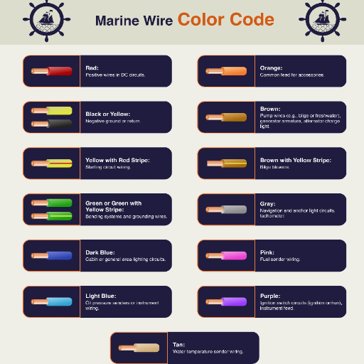
The color codes for marine wires have been standardized to ease electrical system maintenance and avoid confusion. The colors of the wire usually indicate:
Black: DC negative or ground.
Red: DC positive or power supply.
Yellow or Yellow with Red Stripe: Usually denotes switched power or accessories.
Green/Yellow (striped): Earth ground.
Gray: Navigation lights.
Blue: Cabin or instrument lighting.
Understanding these color codes will help you identify and repair any electrical components in your vessel.
The Importance of Wire Color in Marine Applications
Proper wire color identification in marine electrical systems is crucial for maintaining safety, efficiency, and overall system health. High humidity, water salt spray, and vibration form a unique set of conditions within the marine environment, which can lead to potential electrical faults if the system wiring is incorrect. Utilizing standard wire color codes makes the rectification process much easier while reducing the possibility of significant electrical hazards, such as short circuits or fires.
Ensuring the reliability of electrical connections for navigation, lighting, and instrumentation systems by having different codes has been emphasized by worldwide marine standards. Some effects include damage to sensitive equipment, which can even endanger the crew, such as misidentifying a ground wire as a power wire. Statistics from safety reports have shown that incorrect wiring is a significant contributor to marine electrical failures. Observing these color codes substantially reduces such risks.
Present-day improvements in materials and labeling for wires, such as the use of tinned copper conductors and heat-shrink labels, further the cause of color codes in improving longevity and clarity, respectively. Due to its high corrosion resistance, tinned copper significantly extends the lifespan of electrical wiring in marine installations. Additionally, these systems, used in conjunction with traditional color coding, ensure that wires remain readily identifiable even when visibility is poor, or they have been subjected to wear.
Hence, adherence to standardized wiring practices not only protects your vessel but also meets the requirements set by authorities like the American Boat and Yacht Council (ABYC) and ISO standards. The standards set forth highlight color differentiation for primary and auxiliary circuits in an internationally accepted standard for recreational and commercial vessels, respectively. Furthermore, by adhering to these practices, vessel owners and electricians can play their part in ensuring the future of safer marine operations.
Overview of Marine Wiring Standards (ABYC)
The American Boat and Yacht Council (ABYC) provides a much more comprehensive set of standards to ensure the electrical systems used in marine environments are safe, reliable, and efficient. These standards, also referred to as codes in the industry, are intended to reduce risks such as electrical fires, shocks, and system failures. The ABYC recommends that wiring for marine applications utilize marine-grade wiring, which consists of materials capable of withstanding the harsh conditions of marine atmospheres, including moisture, vibrations, and salt corrosion.
Thus, ABYC standards require, among other things, that the wire conductors be made of tinned copper to prevent corrosion and that the correct wire size be used to withstand the anticipated current load. They also specify the use of the color-coding of all wire insulation for the ready identification of various types of circuits and functions. For example, grounding wires are green or green with a yellow stripe, and positive DC wires are red. These standards outline appropriate methods of installation and maintenance that mitigate hazards and are generally in line with international wiring practices.
ABYC also establishes the correct overcurrent protection devices, the circuit breakers or fuses, which must be positioned as close to the power source as practicable to interrupt a fault, thereby reducing damage quickly. Wiring shall also be supported at regular intervals and secured with materials that can withstand marine wear and tear, such as nylon or stainless steel fasteners.
Another noteworthy example that emphasizes the need for these standards is the limitation of voltage drop across the wire. The ABYC recommends a maximum voltage drop of 3% for critical components, such as navigation lights and bilge pumps, and 10% for non-essential equipment. This ensures that critical systems will operate at full load while maintaining safety standards under harsh working conditions.
By following ABYC standards, vessel operators, marine electricians, and others would not only conform to the rules and regulations but also enhance the robustness and reliability of the electrical system onboard. The code continued to evolve, keeping pace with technology and incorporating recommendations from various marine trades, thereby making it more robust and relevant across a wide range of marine applications.
Types of Marine Wires and Their Color Codes
Marine wiring color codes include black, red, yellow, yellow with a red stripe, brown, green, green with a yellow stripe, blue, purple, white, and pink, each serving a specific purpose in marine electrical systems.
|
Color |
Purpose |
|---|---|
|
Black |
Ground (-) |
|
Red |
Positive (+) |
|
Yellow |
Battery Ground |
|
Yellow/Red |
Starting Circuit |
|
Brown |
Pumps & Alarms |
|
Green |
Bonding |
|
Green/Yellow |
AC Grounding |
|
Blue |
Cabin Lighting |
|
Purple |
Ignition Switch |
|
White |
Neutral/Return |
|
Pink |
Fuel Sender |
Marine Wiring Color Code Explained

The marine wiring color code facilitates the identification of wires, ensuring safety, reliability, and uniformity in marine electrical systems. Different colors serve different functions:
Black is for ground (-), which means the negative connection in the circuits.
Red represents positive (+) – it signifies the primary power source.
Yellow refers to the battery ground, ensuring that the battery is properly grounded.
Yellow/Red is for the starting circuit, which carries out the functions related to starting the engine.
Brown makes a connection to pumps and alarms so that they can alert in any condition.
Green is used for bonding, which prevents interference and corrosion.
Green/Yellow for AC grounding ensures the safe discharge of electric current.
Blue is for cabin lighting or interior illumination.
Purple represents the ignition switch, which initiates the engine’s ignition.
White is a neutral or return connection; that is, it completes wiring pathways.
Pink is assigned to the fuel sender, facilitating proper monitoring of fuel levels.
Exact adherence to the system is crucial for the safety and maintenance of any marine environment.
Importance of Color Codes in Wiring
Wiring systems use colors that facilitate the purposes of safety and efficiency in electrical circuits. The colors present a unified cause to identify each wire and its corresponding function. This helps minimize errors during installation and maintenance. If not appropriately wired, for example, it may result in short circuits or equipment damage, or pose a severe fire hazard.
Electrical accidents due to improper wiring account for a significant share of workplace and home incidents, clearly emphasizing the importance of proper color code enforcement. In the United States, according to the National Electrical Code (NEC), electric conductors are typically identified in black and red, while grounding is indicated in green. Similar standards are present throughout the world to ensure uniformity.
Color-coded wiring is crucial in complex systems, such as those found in marine electronics or industrial machines, where large numbers of wires are involved. Proper labeling and adherence to color coding could reduce troubleshooting time by as much as 40%, according to professionals, thereby saving costs and improving reliability. Therefore, knowing and using these codes is a responsibility that cannot be overlooked when working with electrical systems.
Standard Marine Wiring Color Code (ABYC)
The American Boat and Yacht Council provides a standardized color code system for marine wiring, aiming to promote safety, efficiency, and uniform electrical systems. Below are some standard wire color codes used in marine applications:
Black: DC negative or ground connections.
Red: DC positive circuits from the battery switch.
Yellow or Yellow-left stripe wire: A DC negative connection (as per the new standard to
Replace black in some contexts for clarity.
Orange: DC positive circuits from battery to breaker or distribution point.
Brown: DC circuits for pumps such as bilge pumps and livewell pumps.
Green or Green with Yellow Stripe: Grounding connection to eliminate shock hazard (earthing).
White: Shore power AC neutral.
Blue: AC hot circuits or DC circuits for lights and loads.
Purple: Ignition circuits.
Gray: Navigation light circuits.
These guidelines are recommended to be strictly followed by marine electricians and technicians to ensure smooth electrical integration and safety on board. Proper implementation of these steps will enable them to avoid electrical failures and ease maintenance or troubleshooting. Always contact an ABYC-certified professional for accurate implementation.
Standard Colors and Their Functions
Black: Used primarily for grounding and negative applications in DC systems. Black wires will reconnect the electrical circuits to the power source, forming a closed circuit for smooth operation. Grounding is always crucial, as improper grounding can cause shocks or other malfunctions.
Red: In a DC system, it generally denotes positive circuits. Such wires for electricity supply to various components, such as pumps, lights, and radios, are insulated to avoid accidental contact or short circuits.
Yellow (or Yellow with a Stripe): Traditionally used for negative returns in DC systems, particularly when the black color is not favored in some configurations. This color coding helps prevent confusion in complex systems while ensuring clarity during maintenance.
White: Common in AC systems in situations that require a neutral conductor. They allow current to return on AC electrical circuits, balancing active loads safely. White wires typically serve as complements to black “hot” wires within AC wiring.
Blue and Light Blue: Blue wires are used for cabin or panel lighting circuits, while light blue cables are linked to bilge pump controls. Different shades help technicians stay clear when tracing wiring for critical operational systems.
Orange: Identifies accessory and switched power circuits, for example, windshield wipers or auxiliary heaters. Orange wiring usually belongs to systems activated through switches or relays.
Green (or Green with a Yellow Stripe): An AC system for grounding only, green wiring provides a safe means to direct stray currents to the ground, thereby avoiding electrical shocks and complying with stringent safety codes.
Each color plays a significant role in defining the arrangement and maintenance of marine electrical systems. Observing these conventions eliminates misunderstandings, ensures safety, and facilitates speedy repairs. For reliable operation in real-life situations, always label and document electrical circuits properly.
DC Boat Cable Specifications
For maximum safety and performance, when selecting DC cables for your boat, they must fulfill the specifications below:
Wire Gauge: The appropriate American Wire Gauge (AWG) must be determined based on the current load and cable length. Consult an ampacity chart for the correct size.
Marine-Grade Material: Choose tinned copper wires to resist corrosion in marine environments.
Insulation: Must have robust insulation rated for marine use, like PVC or XLPE.
Voltage Rating: Cables should be able to safely carry the system voltage used in the boat (say, 12V, 24V, or 48V).
Labeling: Cable labeling should be done clearly so that it can be easily identified during maintenance or troubleshooting.
This would ensure electrical reliability and ward off any hazards.
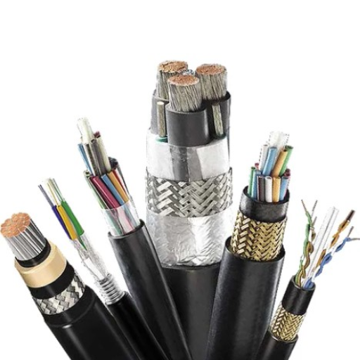
What is DC Boat Cable?
DC boat cable is a crucial component for marine electrical systems, specifically designed for efficiency and safety in shipping and boats that utilize DC power. They are designed for aquatic environments and are prepared to withstand harsh conditions, including moisture, salt, vibration, and temperature. Construction with high-grade materials, such as tinned copper conductors, enhances conductivity and resists corrosion, ensuring reliability over the long term.
DC boat cables typically feature heavy insulation and jacketing made from marine-approved materials, such as polyvinyl chloride (PVC) or cross-linked polyethylene (XLPE). This insulation and jacketing protection resist abrasion, UV exposure, and chemical corrosion, ensuring the long-term life of the cables in harsh conditions. Cable sizing in American Wire Gauge (AWG) is selected based on the current load and circuit length to minimize voltage drop and maintain system efficiency.
Marine safety standards, such as those of the American Boat and Yacht Council (ABYC), prescribe various requirements concerning DC boat cables. For instance, the specification outlines the requirements for cables to meet the highest standards of heat tolerance, flexibility, and fire retardancy. A typical high-quality DC boat cable can operate at temperatures between -40°F and 194°F (-40°C and 90°C) and has current ratings as required by a marine system. It is through the use of these codes that the DC boat cable will add to the safety and efficacy of the vessel’s electrical systems.
Wire Sizes and Their Applications
Choosing the proper wire size is vital to ensure the safety and efficiency of a vessel’s electrical systems. Wire sizes are typically identified by the American Wire Gauge (AWG), where a lower gauge number indicates a thicker wire that can carry more current. For example, a 10 AWG wire is used in circuits carrying up to 30 amps over short distances, while a 16 AWG wire is a better choice for low-current devices, such as lighting circuits with an amperage of 10 amps or less.
It is generally necessary to choose a wire size that considers current flow, the length of the cable run, and the allowed voltage drop. A maximum voltage drop of 3% is generally recommended for critical systems, such as bilge pumps or navigation lights, to ensure these systems operate within their design parameters. In such cases, 6 AWG wire is typically sized for applications with higher current loads, such as heavy-duty inverters or windlass motors, capable of carrying around 50 amps over medium distances.
Environmental parameters, such as heat and vibration, must also be considered when installing wiring in a boat. Opting for oversized wires over the minimum requirements helps mitigate voltage drop and enhance the reliability of a system. Cable runs should be kept as short as possible to minimize resistance and losses, ensuring both safety and optimal performance.
Good marine cables should be well-insulated and rated for flexibility and corrosion resistance, allowing them to withstand the harsh marine environment. For example, tinned copper conductors offer good resistance to oxidation, ensuring their longevity in saline environments. Always refer to marine wiring charts or consult a qualified marine electrician for any issues related to wire size selection, as incorrect wire sizes can cause overheating, power loss, or even fire hazards.
Ground Wire Specifications
Specifications of ground wires are fundamental in ensuring safety and reliability in any electrical or maritime setup. The ground wire primarily serves to route excess current inadvertently into the earth, thereby protecting equipment and individuals from potential electrical hazards. For marine installations, the American Boat and Yacht Council (ABYC) recommends using green-insulated conductors for the ground. The ground wire size should be equal to or greater than the carrying capacity of the most prominent conductor on the circuit it serves.
Tinned copper is selected to minimize corrosion because it is good in conductivity and resistant to saline and humid conditions. Ground wires should also conduct the fault current without allowing more than a 10% voltage drop, according to ABYC guidelines. Proper connectors, such as crimped or soldered terminals, and anti-corrosion treatments, like heat-shrink tubing and dielectric grease, assure a solid, long-lasting connection.
Large wire sizes may be required for larger vessels or high-voltage applications. For example, a 12-volt direct current circuit that carries up to 30 amps needs at least 10 AWG wires, whereas circuits carrying over 100 amps might require 2 AWG or larger wires. Regularly inspect and maintain ground systems, as damaged or corroded ground connections can be unsafe and may lead to equipment failures. Always follow the manufacturer’s recommendations and applicable standards for your particular application.
Connecting Marine Wiring Safely

The first step to ensure a safe marine wiring hookup is to purchase marine-grade materials that resist corrosion and withstand harsh conditions. Always use wires of a suitable size for the amperage and the circuit length. Wires may overheat if misused. Connections should be crimped and heat-shrunk to prevent moisture from entering. Ensure all clamps are tight and free from traces of corrosion. Also, cables must be routed away from heat and abrasion sources and fastened with tie wraps, clamps, or clips. All in all, consider marine wiring standards such as ABYC standards to ensure the safety and reliability of your electrical system.
Best Practices for Connections
High-quality materials and strict standards must be maintained to ensure safety and optimal performance when making electrical connections. Marine wires must be selected according to their gauge size for the electrical load of interest. Marine-grade cables are made of tinned copper strands, which promote resistance against corrosion in hostile environments. According to several studies, using the incorrect wire size can cause voltage drop or overheating, thereby reducing the efficiency and lifespan of your equipment.
Ensure crimped, heat-shrunk connectors are used for all terminations. These connectors create a mechanical bond while sealing it from moisture and contaminants. It has been proven that the corrosion of connectors is significantly reduced by heat-shrink connectors compared to traditional connectors. For added insulation reinforcement, use adhesive-lined heat-shrink tubing.
To prevent connections from loosening over time, ensure that the termination ends are cleaned and inspected on a regular schedule. In general, a corroded connection is a primary cause of electrical failures; the corroded resistance can lead to overheating. Ensure the wires are secured from movement and abrasion during operation with cable ties or clamps; otherwise, it may expose stripped live wire strands.
Follow recognized marine wiring guidelines from institutions such as ABYC to ensure that wire size, circuit protection, and grounding systems are implemented in a manner that provides the vessel’s safety and compliance with its regulatory requirements. Keeping abreast of these recommended practices will enhance reliability and protect one from hazards associated with electricity.
Common Troubleshooting Techniques
Troubleshooting marine electrical systems can follow a systematic approach to identify and address the issues at hand. The voltage drop test is one of the commonly used methods. It helps in locating resistive connections or corrosion in the circuit that leads to poor performance and eventually to more failures. For example, a voltage drop of more than 0.3 volts in a 12V DC circuit could mean an area that requires closer scrutiny.
Another critical step is to inspect the connections and terminals. Loose or corroded connections are usually one of the main reasons for power disruptions. By using a multimeter, you can check the continuity and unexpected resistance. In general, the resistance is supposed to be very low in a circuit that is working correctly.
Circuit protection devices should be viewed with suspicion when so much seems to go wrong. If a fuse blows or a breaker trips, it is a warning sign of an overcurrent through a short circuit or a gross overload in the system. Always maintain or replace fuses with those recommended by the manufacturer to prevent further complications.
Thermal cameras will be most helpful in this case. They reveal hotspots within the electrical system. Hotspots typically indicate excessive resistance or faulty components, posing potential hazards if left unaddressed.
Finally, ensure that battery systems are inspected regularly. Testing for battery voltage and specific gravity (if necessary), and providing clean terminals, will help avoid many headaches in the future. For example, a well-charged 12V lead-acid battery typically reads between 12.6 and 12.8 volts.
Adherence to these techniques ensures not only the speedy resolution of issues but also the improved reliability and safety of the marine vessel’s electrical system.
Ensuring Compliance with Code
One way to ensure compliance with applicable electrical codes is to maintain vessel safety and operability. Among other things, the standard regulations are designed to minimize hazards posed by wiring, batteries, and other electrical components.
This implies that marine wiring must be sized correctly, corrosion-resistant, and capable of withstanding the system’s amperage. ABYC E-11-compliant wiring, for example, is equipped with suitable insulation properties and can safely carry the desired current. Without circuit protection devices, such as breakers or fuses, to prevent overloading or short circuits, electric wiring is incomplete.
Another bonding and grounding system helps prevent stray current corrosion and ensures that all faults are properly discharged. Maintenance records reveal that most electrical faults onboard have been attributed to improper bonding and grounding, justifying adhering to existing standards.
The current status requires regular audits and inspections to ensure compliance with potential changes in regulations or advancements in technology.
Examination of the electrical installation and its supporting documentation ensures that it complies with the current standards in force. In this manner, one can protect not only the integrity of the vessel but also anyone onboard who may become insecure due to non-compliance.
Conclusion and Best Practices

To maintain safety and operational efficiency, the electrical systems of sea vessels must adhere to regulatory standards. Prioritize frequent inspections, keep accurate records, and upgrade equipment as standards evolve. Safety awareness among crew members is to be enhanced through regular training. Being compliant with current regulations and best practices reduces the possibility of risk, ensures vessel efficiency, and meets vessel requirements.
Recap of Wire Color Codes
In wire color codes, I consider it extremely important that the wires are correctly identified to avoid hazards and to ensure safety. In addition to typical systems, wire color schemes vary from country to country. Some common ways to mark them include black or red for live wires, white or gray for neutral, and green or green-yellow for earth wires. Hence, it is essential to be familiar with the color codes when installing, repairing, or inspecting electrical systems onboard.
Final Tips for Marine Wiring
Appropriate marine wiring facilitates safety. Here are some finishing considerations:
Use Marine-Grade Materials: Use only marine-grade wires and components. They are made to withstand marine environment conditions, with corrosion-resistant properties for long-term service.
Follow Voltage and Ampacity Guidelines: Select a wire gauge that is suitable for the prevailing load of current and the allowed voltage drop. Too small cables will heat up; too large ones add unnecessary weight and cost.
Seal and Protect Connections: Electrical connections are designed to be waterproof. Electrical connections should be protected against moisture ingress by heat-shrink tubing and waterproof connectors. Otherwise, ingress of moisture would cause corrosion, thereby reducing their reliability.
Label and Organize Wires: Wires should be labeled to ensure easy identification during repairs or upgrades. The use of cable ties and conduit keeps wiring neat, preventing it from tangling or wearing out due to vibrations.
Maintenance and Inspection: Conduct periodic checks for wear, loose connections, and corrosion to ensure optimal performance. Early realization of faults can maintain a sustainable system.
A safety-compliant, efficient, and long-lasting marine electrical system can be achieved by following these basic recommendations.
Reference Sources
Frequently Asked Questions (FAQs)
What is the Marine Wiring Color Code?
The marine wiring color code is a standardized system used to identify the function of wires in marine applications. This color code helps ensure safety and reliability in electrical connections on boats and other watercraft. It typically follows the guidelines provided by the American Boat and Yacht Council (ABYC).
How does the Marine Wire Color Code differ from standard wiring codes?
Marine wire color codes are specifically designed for use in wet environments, unlike standard wiring codes, which may not account for the effects of moisture exposure. Marine wiring uses different colors to denote specific functions, making it easier for mechanics and technicians to troubleshoot issues on board.
What are the standard wire colors used in Marine Wiring?
Standard wire colors in marine wiring include red for positive connections, black for negative or ground connections, and yellow or blue for accessory circuits. These colors facilitate the quick identification of different types of wires, especially during troubleshooting or installation.
How can I troubleshoot marine wiring issues?
Troubleshooting marine wiring issues begins with identifying the color code of the wires involved. Check for loose connections, frayed wires, or corrosion, especially in connectors and terminals. Using a multimeter can help diagnose electrical problems, such as shorts or open circuits.
What gauge of marine wire should I use for my boat?
The size or gauge of marine wire you should use depends on the current load and the length of the run. Generally, thicker wires (lower gauge numbers) are used for high-current applications, while smaller gauges are suitable for low-voltage electronics, such as lights or speakers.
What type of connectors are recommended for marine wiring?
For marine wiring, it’s best to use connectors that are specifically designed to withstand wet conditions. Heat shrink connectors are recommended as they provide a waterproof seal. Also, terminal connectors should be made of corrosion-resistant materials to ensure longevity and reliability.
Why is it important to follow the Marine Wiring Color Code?
Following the marine wiring color code is crucial for safety and performance. It minimizes the risk of incorrect connections that can lead to electrical failures, fires, or damage to onboard electronics. Proper adherence to the color code facilitates more straightforward repairs and maintenance.
Are there different types of marine wiring for specific applications?
Yes, there are different types of marine wiring tailored for various applications. For instance, primary wires are used for general electrical connections, while specialized cables are designed for specific functions, such as connecting a fuel pump or tachometer. Understanding these differences can help ensure optimal performance in your marine craft.